MMA90105PORTABLE TRANSCEIVER
Midland Radio Corporation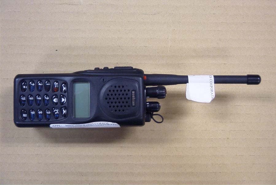
Click to zoom
Application Details
- Equipment Class
- TNF - Licensed Non-Broadcast Transmitter Held to Face
- Date of Grant
- Mar 04, 2007
- Application Purpose
- Original Equipment
- Date of Application
- Mar 04, 2007
- Equipment Note
- PORTABLE TRANSCEIVER
- Frequency Range
- 136.00000000 - 174.00000000
- Company
- Midland Radio Corporation
- Country
- United States
Documents & Files
Document Text
Text extracted from the exhibit documents filed with the FCC. Open a document above to read the original.
Users Manual
7610-4700-1201 Issue A 4700 APCO25 CONVENTIONAL HANDHELD RADIO OPERATING MANUAL © ASELSAN Inc. 3 November 2006 The continuous improvement of its products is the intent of ASELSAN, who reserves the right to make design changes without notice. All rights reserved. reproduction of issue to third parties in any form whatever is not permitted without written permission from the proprietors. PO. Box 101 Yenimahalle, Ankara 06172 TURKEY Tel: +90 312 5921000 * Fax: +90312 3541946 http://www.aselsan.com.tr [email protected] 4700 APCO25 CONVENTİONAL HANDHELD RADIO OPERATING MANUAL 7610-4700-1201 Issue A DEVICE SHOULD BE OPENED BY AUTHORIZED PERSONEL. OTHERWISE IT WILL BE OUT OF WARRANTY. BEFORE GETTING START TO USE THE DEVICE READ USER MANUALS. 4700 APCO25 Conventional Handheld Radio is produced by ASELSAN A.Ş. Usage period of device is 10 year. It is packed and labeled according to commercial packaging standards. 4700 APCO25 CONVENTİONAL HANDHELD RADIO OPERATING MANUAL 7610-4700-1201 Issue A 4700 APCO25 CONVENTİONAL HANDHELD RADIO OPERATING MANUAL 7610-4700-1201 Issue A ATTENTION! If device is stored more than 3 months, crypto key may be erased because of the discharge of the chargeable battery of the crypto board and "EMERGENCY ERASE BATTERY DISCHARGED" appears at the display. In this case device must be connected to an accumulator/battery/power supply and wait for at least 30 minutes at position ON. And then crypto loading process must be repeated. 4700 APCO25 CONVENTİONAL HANDHELD RADIO OPERATING MANUAL 7610-4700-1201 Issue A INTENTIALLY LEFT BLANK. 4700 APCO25 CONVENTİONAL HANDHELD RADIO OPERATING MANUAL 7610-4700-1201 Issue A CONTENTS 1 GENERAL INFORMATION................................................................................................................... 1-1 1.1 GENERAL PROPERTIES.............................................................................................................1-1 1.2 TECHNICAL PROPERTIES.......................................................................................................... 1-3 1.3 PACKAGE CONTENT .................................................................................................................. 1-4 1.3.1 “ASELSAN 4700 Series Handheld Radio” Box ........................................................................ 1-4 1.3.2 “4451 Desktop Charger” Package ............................................................................................ 1-7 1.3.3 “Desktop Charger Adapter” Package ....................................................................................... 1-7 2 PHYSICAL PROPERTIES AND USAGE.............................................................................................. 2-1 2.1 FRONT PANEL ............................................................................................................................. 2-1 2.1.1 LCD Display .............................................................................................................................. 2-2 2.1.2 Key Pad .................................................................................................................................... 2-5 2.2 SIDE PANEL ................................................................................................................................. 2-8 2.2.1 PTT Button................................................................................................................................ 2-8 2.2.2 Mode and Power Change Button.............................................................................................. 2-8 2.2.3 Option / Monitor Button ............................................................................................................. 2-8 2.3 TOP PANEL .................................................................................................................................. 2-9 2.3.1 Emergency Call Button ............................................................................................................. 2-9 2.3.2 Antenna Connector ................................................................................................................... 2-9 2.3.3 Channel Switch ......................................................................................................................... 2-9 2.3.4 Turn On/Off- Volume Switch................................................................................................... 2-10 2.3.5 Option Connector.................................................................................................................... 2-10 2.3.6 Transceiver LED ..................................................................................................................... 2-10 2.4 ALERT TONES AND CALL ALERTS ......................................................................................... 2-10 2.5 LIGHTING ALERTS .................................................................................................................... 2-10 2.6 WRITTEN ALERTS ..................................................................................................................... 2-11 2.7 MENU SCREENS ....................................................................................................................... 2-13 3 MENU USSAGE .................................................................................................................................... 3-1 3.1 SETTINGS MENU......................................................................................................................... 3-1 3.2 CALL LOG MENU ......................................................................................................................... 3-3 3.3 SMS MENU ................................................................................................................................... 3-3 3.4 PROGRAMMED MESSAGE MENU .............................................................…
Text truncated - open the document above for the full version.
Cover Letter(s)
5900 Parretta Drive ● KANSAS CITY, MISSOURI ● 64120 TELEPHONE: (816) 241-8500 ● FAX: (816) 241-5713 EMAIL: [email protected] WEBSITE: www.midlandradio.com Midland Radio Corporation 5900 Parretta Drive, Kansas City, MO. 64120 Phone: (816) 241-8500 Fax: (816) 241-5713 Website: wwwl.midlandradio.com E-Mail: [email protected] December 27, 2006 Federal Communications Commission Authorization and Evaluation Division Confidentiality Request regarding application for certification of FCC ID: (MMA90105) Pursuant to Sections 0.457 and 0.459 of the Commission’s Rules, we hereby request confidential treatment of information accompanying this application as outlined below: Block Diagram Schematic Diagram(s) Operational Description The above materials contain trade secrets and proprietary information not customarily released to the public. The public disclosure of these materials may be harmful to the applicant and provide unjustified benefits to its competitors. The applicant understands that pursuant to Section 0.457 of the Rules, disclosure of this application and all accompanying documentation will not be made before the date of the Grant for this application. Sincerely, David Berneking Midland Radio Corporation 5900 Parretta Drive Kansas City, MO 64120 .
Cover Letter(s)
5900 Parretta Dr ● KANSAS CITY, MISSOURI ● 64120 TELEPHONE: 816-241-8500 FAX: (816) 241-5713 WEBSITE: www.midlandradio.com 3-2-2007 To Whom It May Concern: Midland requires the Part 90 FCC grant list frequencies outside of Part 90 assignments because state and local government users specify operation outside of Part 90 so that they can interoperate with Federal agencies. The issue being that user's that are not under NTIA frequency coordination must use radios that have FCC approval. Sincerely, David Kingsolver Director of Engineering Midland Radio Corporation
External Photos
MIDLAND RADIO CORP. FCC ID: MMA90105 EXTERNAL PHOTOS
ID Label/Location Info
FCC ID Label Sample - Portable Model: STP105B FCC ID: MMA90105 IC: 3690A-90105 S/N: 060140100 ---------------------------------------------------------------------------- FCC ID Label Sample - Mobile Model: STM1050B FCC ID: MMA901050 IC: 3690A-901050B S/N: 060140100
ID Label/Location Info
FCC Label Location Back of Portable, Bottom: Model: STP105B For VHF. FCC ID: MMA90105 IC No. Serial number format: YYMMxxxxx YY = year MM = month Xxxxx = sequential serial number Example: 061240100 First production serial number to start 061240100 Remove date code. OK Rev level for first production.
ID Label/Location Info
5900 Parretta Dr ● KANSAS CITY, MISSOURI ● 64120 TELEPHONE: 816-241-8500 FAX: (816) 241-5713 WEBSITE: www.midlandradio.com 03-05-2007 To Whom It May Concern: Ref: FCC ID MMA9015 This device is handheld. It is not feasible to place the FCC identifier label in a normally visible area. 1) The FCC identifier will be visible at the time of purchase. 2) The area where the label is placed will not require any special tools for access. The FCC label will not be placed on a removable part. 3) The FCC identifier, model no. or FCC logo will be on the label and meet all general labeling requirements or policies that apply for Certification, Verification or DOC; e.g. for Certification, for handheld devices. Sincerely, David Kingsolver Director of Engineering
Internal Photos
MIDLAND RADIO CORP. FCC ID: MMA90105 INTERNAL PHOTOS
Parts List/Tune Up Info
4710 Portable Radios FCC Certification Documents 1 6. List of semiconductor designations and functions : GENERIC PART NUMBER FUNCTION BC857BT AF TRANSISTOR BC847BT AF TRANSISTOR BCX54-10 AF TRANSISTOR DUAL ASW SPDT ANALOG SWITCH MAX4544 ANALOG SWITCH TDA1519CSP AUDIO AMPLIFIER TDA8541T AUDIO AMPLIFIER AD74111 AUDIO CODEC CMX881E1 BASEBAND PROCESSOR DTA144EEA BIAS RESISTOR TRANSISTOR DTC144EE BIAS RESISTOR TRANSISTOR UMD12N. BIAS RESISTOR TRANSISTOR UMD3N. BIAS RESISTOR TRANSISTOR UMH11N BIAS RESISTOR TRANSISTOR UMH2N BIAS RESISTOR TRANSISTOR MAX4372TEUK-T CURRENT SENSOR AT45DB041B DATA MEMORY TMS320VC5416 DIGITAL SIGNAL PROCESSOR DS1803E-100 DIGITAL POTENTIOMETER DS1807E DIGITAL POTENTIOMETER TA31136FN FM DEMODULATOR LMX2335UTMX FREQUENCY SYNTHESIZER MAX7301AGL I/O EXPANDOR G128064-4F LCD ZMOSG56W DIK LIGHT EMITTING DIODE ZMOSG56W LIGHT EMITTING DIODE LVR 9V LINEAR REGULATOR MIC5206-BM5 LINEAR REGULATOR TK11233CMCL LINEAR REGULATOR TK11250CMCL LINEAR REGULATOR 74AHC1G125 LOGIC GATE M30626FHPGP MICROCONTROLLER LM20 OPERATIONAL AMPLIFIER LMC7111 OPERATIONAL AMPLIFIER LMV321 OPERATIONAL AMPLIFIER LMV358. OPERATIONAL AMPLIFIER SI3457DV P-CHANNEL MOSFET HSMP3824 PIN DIODE MA2S728 PIN DIODE MA4P7102F PIN DIODE PIN 3985-TLG PIN DIODE DK2a-12V RELAY 12 VDC AH3 RF AMPLIFIER SGA-5486 RF AMPLIFIER TA4004F RF AMPLIFIER RA30H1317M RF POWER AMPLIFIER 2SC5195 RF TRANSISTOR BF512 RF TRANSISTOR BFR93AW RF TRANSISTOR RS232-2X2 RS232 TRANCEIVER RS232-5X3 RS232 TRANCEIVER 1SS383 SCHOTTKY DIODE 1SS388 SCHOTTKY DIODE MMBTA42 SMALL SIGNAL TRANSISTOR CY62128V SRAM MEMORY MAX1837 STEP-DOWN DC-DC CONVERTOR SM15T18A TRANSIENT VOLTAGE SUPPRESSOR MG064L18X500T TRANSIENT VOLTAGE SUPPRESSOR MAX836EUS-T VOLTAGE MONITOR BZX84B7V5 ZENER DIODE
Parts List/Tune Up Info
4710 Portable Radios Methods of Adjustments 1 5 METHODS OF ADJUSTMENTS Adjustment Set-up for 4710 Portable Radios 4710 Portable (5820-4710-0000S) ANTENNA (Ext-Mic) OPT-1 (GND) OPT-7 (RS232-RX) OPT-5 (RS232-TX) OPT-2 (BAT +) BATT-3 (BAT –) BATT-1 DC Power Supply A4700 Audio Analyzer HP 8903B Frequency Counter HP 53132A Modulation Analyzer HP 8901B 10dB 10dB 1W 10dB 1W RF Power Mete r 10dB 10W RF Signal Generator HP 8657B Test Pattern Generator TDU 4700 680Ω 100 μF + Mic 600 Ω Matching 10dB 1W APCO 25 Test Set IFR 2975 10dB 1W Battery Eliminator 4710 Portable Radios Methods of Adjustments 2 a) Connect the equipment as illustrated. b) Set the Power Supply output voltage to 7.5 volts and current limit to 2 amperes. c) Set the RF Signal Generator output to its minimum level. d) Set the Audio Analyzer output impedance to 600 Ω and amplitude to 0 Vrms. e) Set the Modulation Analyzer to measure peak deviation. Set the audio bandwith for ≤ 5 Hz to ≥ 15 kHz. Turn the de-emphasis function off. f) Run A4700.exe on the PC. g) Click on the Read Radio icon and enter the “Radio Adj.” menu. h) Adjustments specified in steps 5.1–5.12 should be applied consecutively. i) Adjustments specified in steps 5.1–5.12 should be applied to all models unless otherwise specified. j) If “Analog Frequency Adjustment” is changed, then “C4FM Receive Level Adjustment” has to be repeated. k) If “Modulation Flatness Adjustment” or “Modulation Limiting Adjustment” is changed, then the successive modulation and deviation adjustments have to be repeated. l) RF signal modulated with Standart Transmitter Low Deviation Pattern in step 5.12 can be obtained from IFR 2975 Apco Test Set or an RF Signal Generator connected to TDU4700 Test Pattern Generator, which is calibrated according to the method specified in step m). m) Connect TDU 4700 output to RF Signal Generator EXT DC FM input. Connect RF Signal Generator output to Modulation Analyzer RF input. Run TDU4700.exe on the PC and select Standart Symbol Rate Pattern on TDU4700 window. Set RF Signal Generator output level to 10 dBm. Adjust RF Signal Generator modulation level to obtain 2800±30 Hz deviation on Modulation Analyzer. NOTE: The alternative test equipments, which can be used in the adjustment set-up, should be compatible to those specified in EIA-603-B and/or TIA-102.CAAA-B standards. 4710 Portable Radios Methods of Adjustments 3 5.1 RF Output Power Adjustment a) Enter “RF Output Power Adjustment” window and click “Transmit”. b) Adjust RF Output Power Parameter to obtain the measured power levels to be equal to the selected power levels for each selected frequency. 5.2 Analog Frequency Adjustment 25 kHz a) Enter “Analog Frequency Adjustment 25 kHz” window and click “Transmit”. b) Adjust Analog Frequency Parameter 25 kHz until the frequency error to be less than 10 Hz at the test frequency. 5.3 Analog Frequency Adjustment 12.5 kHz a) Enter “Analog Frequency Adjustment 12.5 kHz” window and click “Transmit”. b) Adjust Analog Frequency 12.5 kHz parameter until frequency error to be less than 10 Hz at the test frequency. 5.4 Digital Frequency Adjustment Applicable only to digital models. a) Enter “Digital Frequency Adjustment” window and click “Transmit”. b) Adjust Digital Frequency parameter until frequency error to be less than 10 Hz at the test frequency. 5.5 Modulation Flatness Adjustment a) Enter “Modulation Flatness Adjustment” window, select the lower test frequency and click “Transmit”. b) Set the audio signal frequency to 50 Hz and adjust the audio signal level to obtain 3000 Hz deviation on Modulation Analyzer. The audio signal level should be 100±20 mVrms at the OPT-1 (Ext-Mic) input of the radio. c) Set the audio signal frequency to 50 Hz, click “MOD-2” and set the measured audio signal level on Audio Analyzer as 0.0 dB reference. d) Set the audio signal frequency to 3000 Hz, click “MOD-1” and adjust MOD-1 parameter to obtain 0.0±0.05 dB audio signal level on Audio Analyzer. e) Repeat the steps c) and d). f) Select the medium test frequency. 4710 Portable Radios Methods of Adjustments 4 g) Set the audio signal frequency to 50 Hz, click “MOD-2” and adjust MOD-2 parameter to obtain 0.0±0.05 dB audio signal level on Audio Analyzer. h) Set the audio signal frequency to 3000 Hz, click “MOD-1” and adjust MOD-1 parameter to obtain 0.0±0.05 dB audio signal level on Audio Analyzer. i) Repeat the steps g) and h). j) Select the higher test frequency and repeat the steps g) and h). k) Repeat the step j). 5.6 Modulation Limiting Adjustment a) Enter “Modulation Limiting Adjustment” window and click “Transmit”. b) Set the audio signal frequency to 1 kHz and level to 2 times of the level in step 5.5-b). c) Adjust Modulation Limit parameter until deviation to be 4600±50 Hz. 5.7 FM Deviation Adjustment a) Enter “FM Deviation Adjustment” window and click “Transmit”. b) Set the audio signal frequency to 1 kHz and level to 100 mVrms at OPT-1 input. c) Adjust FM Deviation parameter until deviation to be 4500±50 Hz. d) Set the audio signal amplitude to 0 mVrms. 5.8 C4FM Deviation Adjustment Applicable only to APCO25 models. a) Enter “C4FM Deviation Adjustment” window and click “Transmit”. c) Adjust C4FM Deviation parameter until deviation to be 2800±30 Hz. 5.9 GMSKFM Deviation Adjustment Applicable only to SK2/SAGE models. a) Enter “GMSKFM Deviation Adjustment” window and click “Transmit”. c) Adjust GMSKFM Deviation parameter until deviation to be 3800±40 Hz. 4710 Portable Radios Methods of Adjustments 5 5.10 Squelch Adjustment a) Enter “Squelch Adjustment” window. b) Set the RF signal frequency to the test frequency, modulation frequency to 1 kHz, deviation to 3 kHz and adjust the RF signal level for 10 dB SINAD. This RF level referred at the antenna input should be less than –119 dBm. c) Adjust the Squelch parameter from RX LED is off condition to the position where RX LED is just on or click “AUTOMATIC” for the automatic squelch adjustment. d) Adjust the RF signal level in 0.2 dB incre…
Text truncated - open the document above for the full version.
Parts List/Tune Up Info
4710 Portable Radios FCC Certification Documents 2 9. Transmitter tune-up (alignment) procedure : There is no owners/operators applicable transmitter tune-up (alignment) procedure for Aselsan R4711 radio. R4711 radio transmitter conducted carrier output power is programmable between 0.5 watts and 5 watts at 3 preset levels by using AP25DMY.exe (APCO25 Data Base Manager) and AP25TP47 Programmer. Preset power levels are selectable by owners/operators by means of the power level selector button. Selected power levels are displayed on the upper line of LCD screen as “L” indicating low power level, “M” indicating medium power level and “H” indicating high power level. Default values for the power levels are as follows: L (low power level) = 1 watt M (medium power level) = 2 watts H (high power level) = 5 watts In Aselsan, power control circuits of R4711 radio is calibrated according to 4700 Adjustment and Test Procedures given below. NOTE: A4700.exe Adjustment and Test software is intended to be used by Aselsan/Authorized parties only. 4710 Portable Radios FCC Certification Documents 3 5 ADJUSTMENTS Adjustment Set-up for 4710 Portable Radios 4710 Portable (5820-4710-0000S) ANTENNA (Ext-Mic) OPT-1 (GND) OPT-7 (RS232-RX) OPT-5 (RS232-TX) OPT-2 (BAT +) BATT-3 (BAT –) BATT-1 DC Power Supply A4700 Audio Analyzer HP 8903B Frequency Counter HP 53132A Modulation Analyzer HP 8901B 10dB 10dB 1W 10dB 1W RF Power Mete r 10dB 10W RF Signal Generator HP 8657B Test Pattern Generator TDU 4700 680Ω 100 μF + Mic 600 Ω Matching 10dB 1W APCO 25 Test Set IFR 2975 10dB 1W Battery Eliminator 4710 Portable Radios FCC Certification Documents 4 a) Connect the equipment as illustrated. b) Set the Power Supply output to 7.5 volts and current limit to 2 amperes. c) Set the RF Signal Generator output to its minimum level. d) Set the Audio Analyzer output impedance to 600 Ω and amplitude to 0 Vrms. e) Set the Modulation Analyzer to measure peak deviation. Set the audio bandwith for ≤ 5 Hz to ≥ 15 kHz. Turn the de-emphasis function off. f) Run A4700.exe on the PC. g) Click on the Read Radio icon and enter the “Radio Adj.” menu. 5.1 RF Output Power Adjustment a) Enter “RF Output Power Adjustment” window and click “Transmit”. b) Adjust RF Output Power Parameter to obtain the measured power levels to be equal to the selected power levels for each selected frequency.
Test Report
849 NW STATE ROAD 45 NEWBERRY, FL 32669 USA PH: 888.472.2424 OR 352.472.5500 FAX: 352.472.2030 EMAIL: [email protected] HTTP://WWW.TIMCOENGR.COM FCC PART 90 TEST REPORT APPLICANT MIDLAND RADIO CORPORATION 5900 PARRETTA DRIVE KANSAS CITY, MO 64120 FCC ID MMA90105 MODEL NUMBER STP105B PRODUCT DESCRIPTION PORTABLE TRANSCEIVER DATE SAMPLE RECEIVED 11/1/2006 DATE TESTED 12/20/2006 TESTED BY JOSEPH SCOGLIO APPROVED BY MARIO DE ARANZETA TIMCO REPORT NO. 3035AUT6TestReport.doc TOTAL PAGES 31 TEST RESULTS PASS FAIL THE ATTACHED REPORT SHALL NOT BE REPRODUCED EXCEPT IN FULL WITHOUT THE WRITTEN APPROVAL OF TIMCO ENGINEERING, INC. Certificate # 0955-01 TABLE OF CONTENTS STATEMENT OF COMPLIANCE.................................................................................. 3 GENERAL INFORMATION .......................................................................................... 4 TEST PROCEDURES ................................................................................................. 5 RF POWER OUTPUT .................................................................................................. 6 OTHER MODULATION CHARACTERISTICS ............................................................... 7 MODULATION CHARACTERISTICS............................................................................ 8 VOICE MODULATED COMMUNICATION EQUIPMENT ............................................. 10 Part 2.1049 OCCUPIED BANDWIDTH .................................................................. 14 METHOD OF MEASURING CONDUCTED EMISSIONS ............................................. 21 FIELD STRENGTH OF SPURIOUS EMISSIONS......................................................... 22 FREQUENCY STABILITY.......................................................................................... 24 TRANSIENT FREQUENCY BEHAVIOUR ................................................................... 25 TRANSIENT FREQUENCY RESPONSE PLOTS .......................................................... 27 EMC TEST EQUIPMENT .......................................................................................... 31 Applicant: MIDLAND RADIO CORPORATION FCC ID: MMA90105 Report: M\MidlandRadio_MMA\3035AUT6\3035AUT6TestReport.doc Page 2 of 31 STATEMENT OF COMPLIANCE This equipment has been tested in accordance with the standards identified in the referenced test report. To the best of my knowledge and belief, these tests were performed using the measurement procedures described in this report and demonstrate that the equipment complies with the appropriate standards. No modifications were made to the equipment during testing in order to demonstrate compliance with these standards. I attest that the necessary measurements were made by me or under my supervision, at Timco Engineering, Inc. located at 849 N.W. State Road 45, Newberry, Florida 32669 USA. Certificate #0955-01 Authorized by: Mario de Aranzeta Signature: < Mario de Aranzeta> Function: Engineer Date: 1/8/2007 Applicant: MIDLAND RADIO CORPORATION FCC ID: MMA90105 Report: M\MidlandRadio_MMA\3035AUT6\3035AUT6TestReport.doc Page 3 of 31 GENERAL INFORMATION DUT Specification The test results relate only to the items tested. DUT Description PORTABLE TRANSCEIVER FCC ID MMA90105 Model Number STP105B Serial Number N/A Operating Frequency 136-174 No. of Channels Single Type of Emission F3E Modulation FM 110–120Vac/50– 60Hz DC Power DUT Power Source Battery Operated Exclusively Prototype Pre-Production Test Item Production Fixed Mobile Type of Equipment Portable Antenna Helical Antenna Connector SMA Applicant: MIDLAND RADIO CORPORATION Test Condition The DUT was tested in the laboratory with normal temperature and humidity. The temperature was 26ºC with a relative humidity of 50%. Modification to the DUT None Test Exercise The DUT was placed in continuous transmit Applicable StandardsTIA 603 FCC CFR 47 Part 90 Test Facility Timco Engineering Inc. at 849 NW State Road 45 Newberry, FL 32669 USA. FCC ID: MMA90105 Report: M\MidlandRadio_MMA\3035AUT6\3035AUT6TestReport.doc Page 4 of 31 TEST PROCEDURES Power Line Conducted Interference: If required for DUT, the procedure used was ANSI/TIA 603-C:2004 using a 50uH LISN. Both lines were observed with the DUT transmitting. The bandwidth of the spectrum analyzer was 10 kHz with an appropriate sweep speed. Bandwidth 20 dB: The measurements were made with the spectrum analyzer's resolution bandwidth (RBW) = 1 MHz and the video bandwidth (VBW) = 3 MHz and the span set as shown on plot. Power Output: The RF power output was measured at the antenna feed point using a peak power meter. Antenna Conducted Emissions: The RBW = 100 kHz, VBW = 300 kHz and the span set to 10.0 MHz and the spectrum was scanned from 30 MHz to the 10 th Harmonic of the fundamental. Above 1 GHz the resolution bandwidth was 1 MHz and the VBW = 3 MHz and the span to 50 MHz. Radiation Interference: The test procedure used was ANSI C63.4-2003 using an Agilent spectrum receiver with pre-selector. The bandwidth (RBW) of the spectrum receiver was 100 kHz up to 1 GHz and 1 MHz above 1 GHz with an appropriate sweep speed. The VBW above 1 GHz was 3 MHz. The analyzer was calibrated in dB above a microvolt at the output of the antenna. Applicant: MIDLAND RADIO CORPORATION FCC ID: MMA90105 Report: M\MidlandRadio_MMA\3035AUT6\3035AUT6TestReport.doc Page 5 of 31 RF POWER OUTPUT Rule Part No.: Part 2.1046(a), Part 87.131 Test Requirements: Method of Measurement: RF power is measured by connecting a 50-ohm, resistive wattmeter to the RF output connector. With a nominal battery voltage, and the transmitter properly adjusted the RF output measures: For the device has a fixed antenna, RF power is measured as ERP as the antenna is permanently attached. The substitution method was used. With a nominal battery voltage, and the transmitter properly adjusted the RF output measures: Test Setup Diagram: Test Data: OUTPUT POWER: HIGH –5.00 Watts Conducted LOW - 1.00 Watts Conducted Part 2.1…
Text truncated - open the document above for the full version.
Contact Information
Applicant
Butch Rittmann(Director of Operations)
Test Firm
Timco Engineering, Inc.Sid Sanders
Technical Specifications
| # | Rule Parts | Frequency Range | Power Output | Emission | Tolerance |
|---|---|---|---|---|---|
| 1 | 9 | 136 MHz - 174 MHz | 1 W | 11K0F2D | 2.5 ppm |
Other Applications from Midland Radio Corporation

MMAMXMC95
Jun 10, 2026Wireless Bluetooth Microphone
Equipment Class
JAB - Part 15 Class B Digital Device
MMAMXT295
Jun 08, 2026GMRS Radio
Equipment Class
TNF - Licensed Non-Broadcast Transmitter Held to Face
MMACLIPTALK
Apr 27, 2026Transceiver
Equipment Class
DTS - Digital Transmission System
MMABR200S
Jan 13, 2026BUSINESS BAND TWO-WAY RADIO
Equipment Class
TNF - Licensed Non-Broadcast Transmitter Held to Face
MMAGXT67
Oct 29, 2023GMRS RADIO
Equipment Class
TNF - Licensed Non-Broadcast Transmitter Held to Face