MMAG220Combination FRS/GMRS Transceiver
Midland Radio Corporation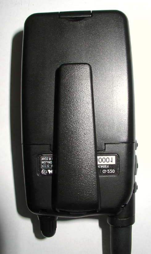
Click to zoom
Application Details
- Equipment Class
- FRF - Part 95 Family Radio Face Held Transmitter
- Date of Grant
- Apr 22, 2002
- Application Purpose
- Original Equipment
- Date of Application
- Mar 06, 2002
- Equipment Note
- Combination FRS/GMRS Transceiver
- Frequency Range
- 467.56250000 - 467.71250000
- Company
- Midland Radio Corporation
- Country
- United States
Documents & Files
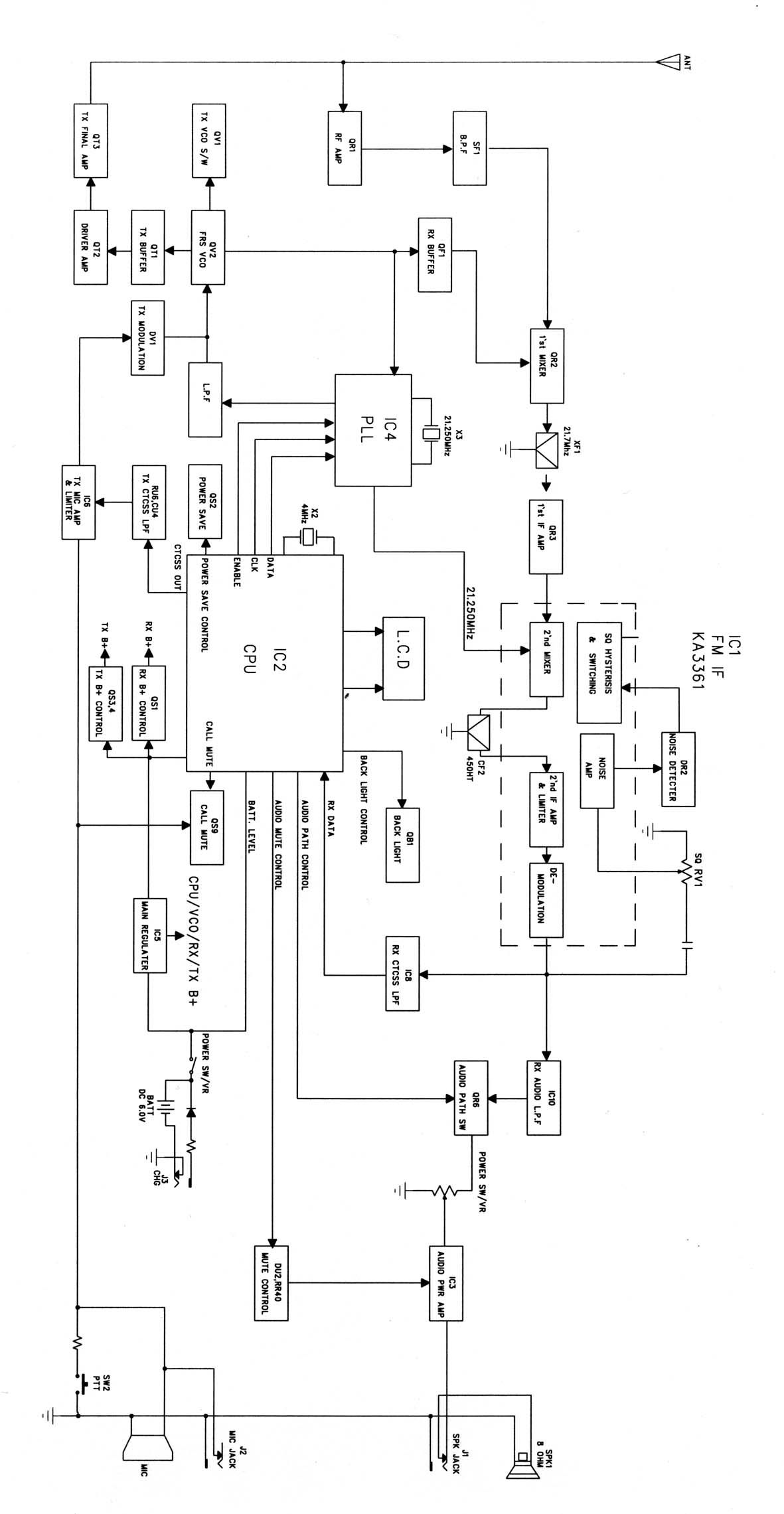
Document Text
Text extracted from the exhibit documents filed with the FCC. Open a document above to read the original.
External Photos
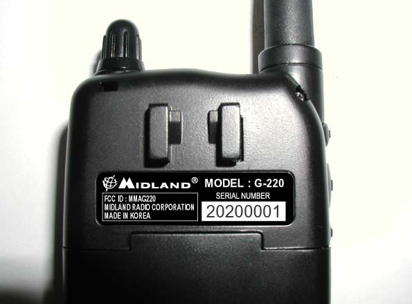
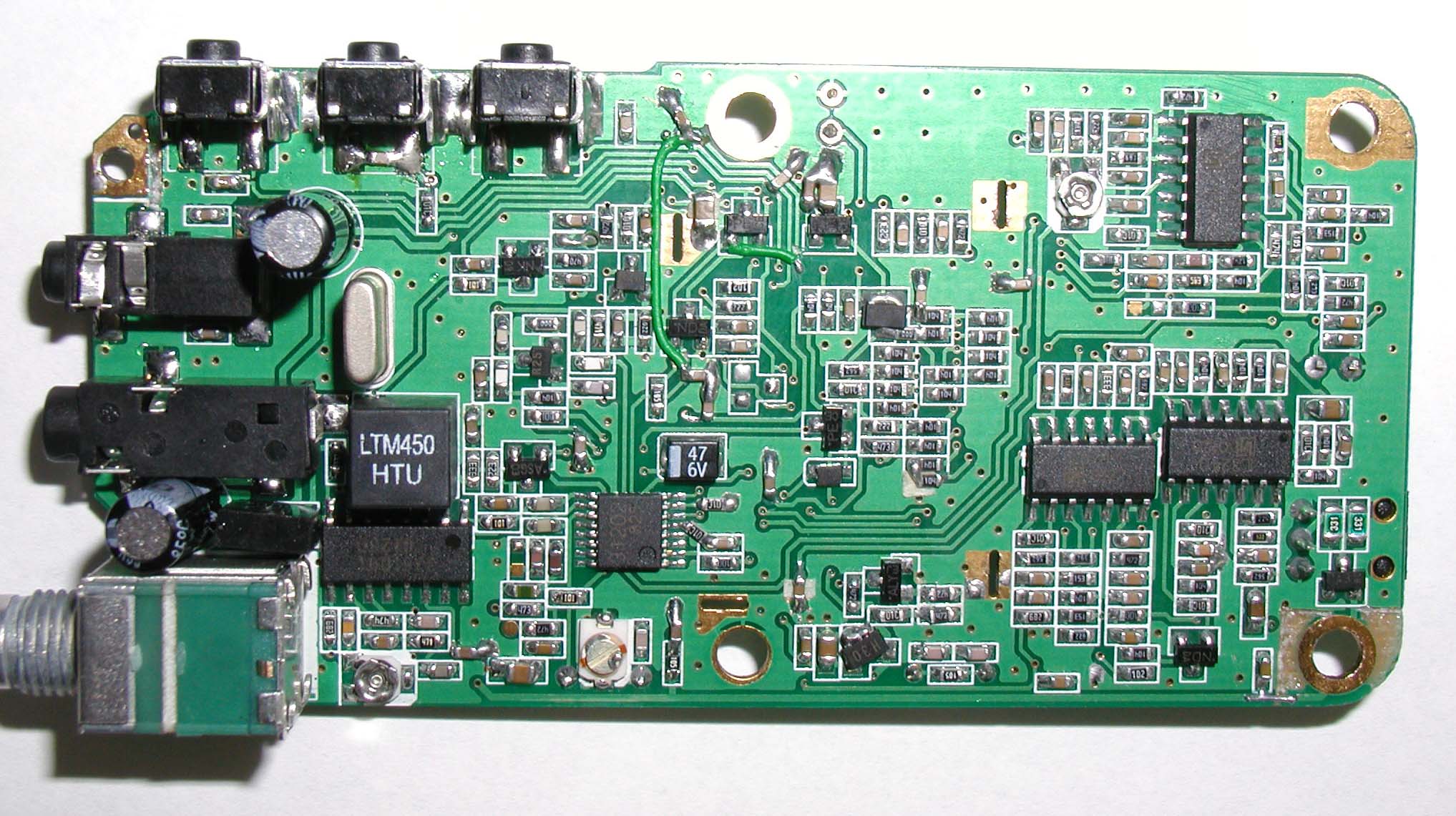
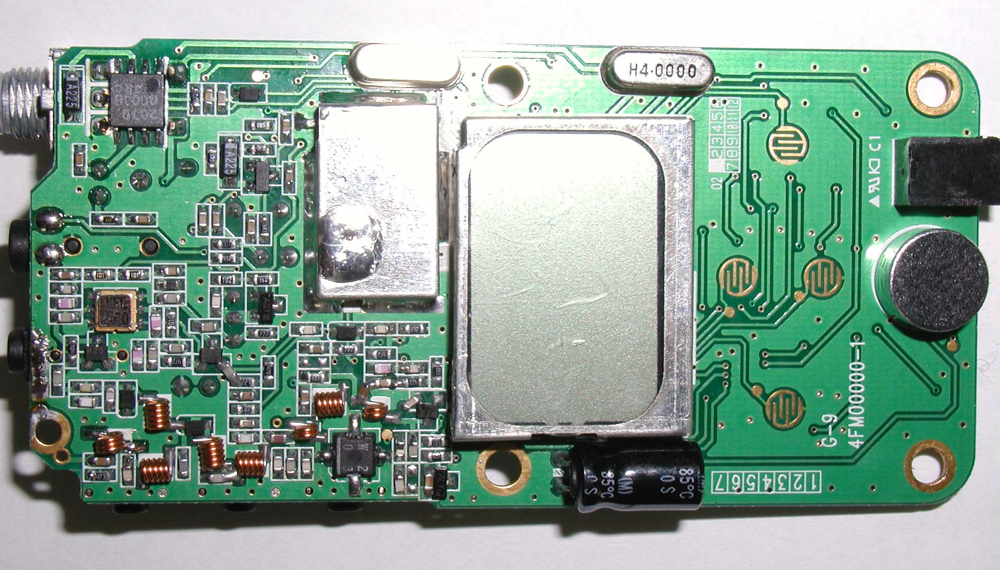
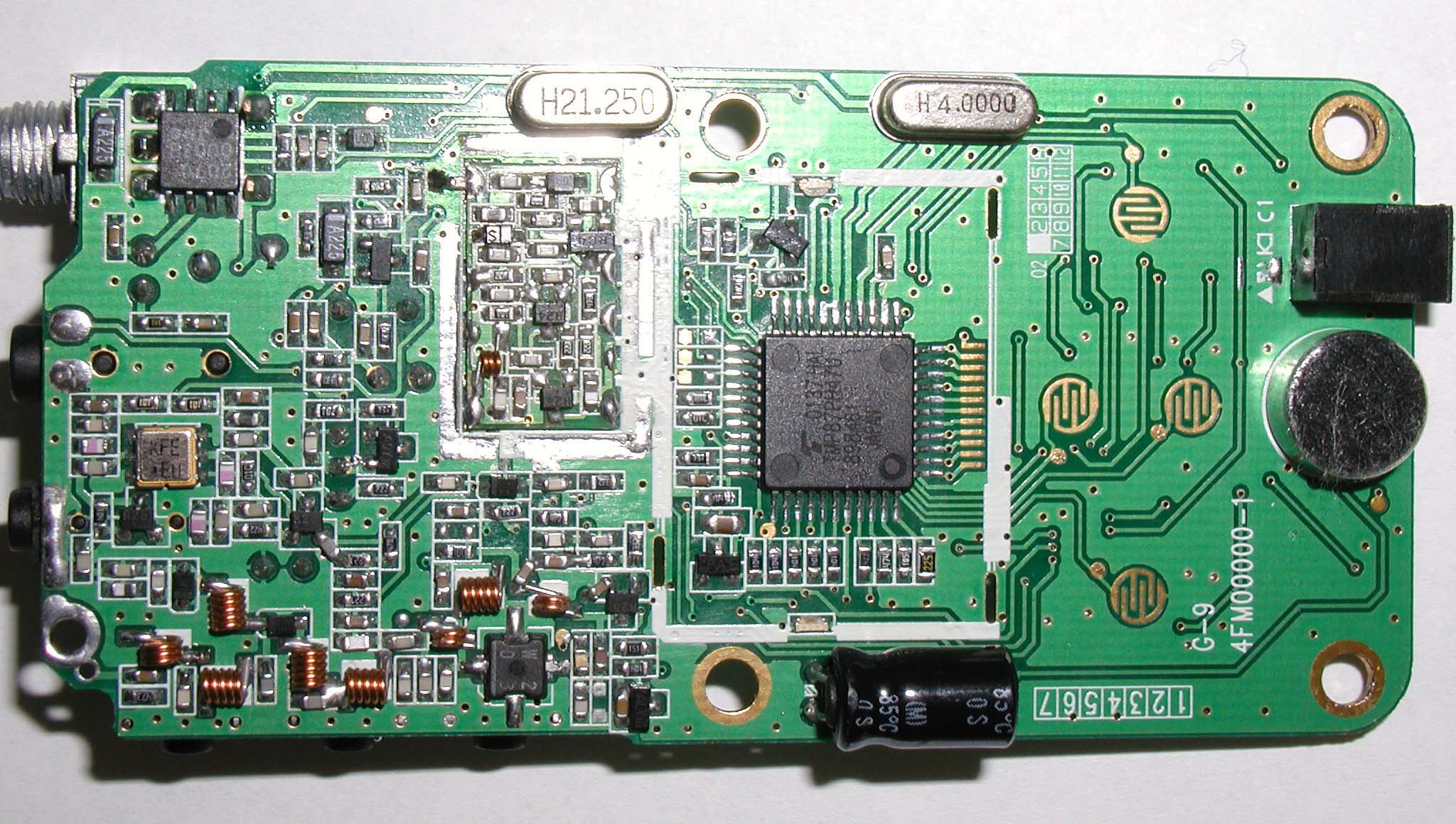
Front View Rear view Left Side View Right Side View Botto m View Top View
Operational Description
Operational Description Your Midland model G-220 combines access to FRS (Family Radio Service) channels with operation on GMRS channels. The Family Radio Service is provided for by the FCC and is totally license free. Use of the GMRS channels requires FCC licensing. You can use your G-220 on the FRS UHF FM band for personal communications at no charge. The G-220 uses maximum allowable power on FRS for range up to 2 miles and higher power on GMRS channels to provide you with line-of-sight communications for a range up to 5 miles. Use for fishing, hunting, picnics, biking, business, or any other activity w here communications are needed for convenience or safety. The model G-220 operates on 22 channels of FRS and GMRS combined to provide the best in quiet and private communication. Channels 1 through 7 are co-shared by FRS and GMRS users. This means that a person with a FRS unlicensed radio can talk to a person using a licensed GMRS radio on these channels. Channels 8 through 14 are exclusively FRS channels. Radios made strictly for GMRS use do not cover these channels. Channels 15 through 22 are exclusively GMRS channels. Radios made for FRS use do not cover these channels. Also this radio offers power save, and auto-squelch. The model G-220 incorporates channels with 38 different CTCSS codes to provide the best in quiet communications. Also this radio offers scan, power save, and a multifunction back-lighted liquid crystal display.
Parts List/Tune Up Info
Alignment instructions WARNING Any repairs or adjustments should be made under the supervision of a Qualified radiotelephone technician. TRANSMITTER 1. Power Supply Voltage The Power supply voltage should be set for 6.0 VDC measured at the radio During transmit. Periodically check the power supply voltage during the alignment procedure. 2. Frequency Setting A. Connect a frequency counter or Communications Service Monitor to the Antenna connector through an RF power attenuator (5 watt minimum rating, 20 dB minimum attenuation). B. Depress the PTT switch. C. Adjust the CTX1 trimmer capacitor such that The output frequency is equal to the channel frequency with a maximum error of +/- 200 Hz. D. Release the PTT switch. 3. Output Power Alignment. A. Set the power supply voltage for 6.0 VDC. B. Connect a Communications Service Monitor or a wattmeter and dummy load To the antenna connector. C. Depress the PTT switch. D. To be convinced for 2Watt (50 ohm load) output power with a maximum error of +/- 0.15 Watts. E. Release the PTT switch. 4. Deviation Adjustment. A. Connect an audio generator . The audio frequency should be set at 1 KHz. B. Connect an FM deviation meter or Communications Service Monitor to the antenna connector through an RF power attenuator (5 watt minimum rating, 20 dB minimum attenuation). Set the monitor to read peak deviation. C. Depress the PTT switch. D. Adjust RV3 for +/- 1.8KHz maximum deviation. E. Release the PTT switch.
Contact Information
Applicant
Butch Rittmann(Director of Operations)
Technical Contact
Hyak Laboratories, Inc.Rowland S Johnson
[email protected](703) 451-1188
7011 Calamo St., Suite 107 · Springfield, Virginia · United States
Non-Technical Contact
Hyak Laboratories, Inc.Georgia Hall
[email protected](703) 451-1188
Test Firm
Carl T. Jones CorporationCarl Jones
Technical Specifications
| # | Rule Parts | Frequency Range | Power Output | Emission | Tolerance |
|---|---|---|---|---|---|
| 2 | 95B | 467.5625 MHz - 467.7125 MHz | 410.00 mW | 11K0F3E | 0.00025 % |
Other Applications from Midland Radio Corporation

MMAMXMC95
Jun 10, 2026Wireless Bluetooth Microphone
Equipment Class
JAB - Part 15 Class B Digital Device
MMAMXT295
Jun 08, 2026GMRS Radio
Equipment Class
TNF - Licensed Non-Broadcast Transmitter Held to Face
MMACLIPTALK
Apr 27, 2026Transceiver
Equipment Class
DTS - Digital Transmission System
MMABR200S
Jan 13, 2026BUSINESS BAND TWO-WAY RADIO
Equipment Class
TNF - Licensed Non-Broadcast Transmitter Held to Face
MMAGXT67
Oct 29, 2023GMRS RADIO
Equipment Class
TNF - Licensed Non-Broadcast Transmitter Held to Face