MMAG300FRS & GMRS Transceiver
Midland Radio Corporation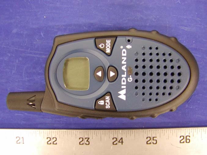
Click to zoom
Application Details
- Equipment Class
- FRF - Part 95 Family Radio Face Held Transmitter
- Date of Grant
- Jul 02, 2003
- Application Purpose
- Original Equipment
- Date of Application
- Apr 30, 2003
- Equipment Note
- FRS & GMRS Transceiver
- Frequency Range
- 462.56250000 - 467.71250000
- Company
- Midland Radio Corporation
- Country
- United States
Documents & Files
Document Text
Text extracted from the exhibit documents filed with the FCC. Open a document above to read the original.
Users Manual
http://www.midlandradio.com - 1 - Owner’s Manual For Model G-300 GMRS/FRS Radio FEATURING • 22 Channels • 38 CTCSS codes • VOX • Monitor function • Call Alert • Back-Lit LCD • Vibrate Alert • Scan • Roger Beep Tone http://www.midlandradio.com - 2 - Warning: User may not adjust any component that results in violation of FCC rules. There are no user internal serviceable nor adjustable parts. No transmitter components (crystals semiconductors etc.) may be adjusted or replaced by any user. Refer repairs to authorized factory service personnel. This device complies with Part 15 of the FCC rules. Operation is subject to the following two conditions: (1) this device does not cause harmful interference, and (2) this radio must accept any interference received, including interference that may cause undesired operation. To maintain compliance with FCC’s RF exposure guidelines, For body-worn operation, this radio has been tested and meets the FCC RF exposure guidelines when used with Midland Radio Corp. accessories supplied or designated for this product. Use of other accessories may not ensure compliance with FCC RF exposure guidelines. (Tested with Headset Model:AVP-1.) http://www.midlandradio.com - 3 - Use and Care 1. Do not use alcohol or cleaning solutions to clean the radio. 2. Do not immerse the radio in water. 3. Use a soft damp cloth to clean the radio 4. Dry the radio with dry lint-free cloth should it get wet. 5. Turn off the radio and remove the batteries during long-term storage. http://www.midlandradio.com - 4 - Index Accessories 4 Accessories order form 5 Introduction 6 FCC Licensing Information 6 Controls and Buttons 7 LCD Display 8 Installing Batteries 9 Charging the Batteries 10 Operation 11-18 Problems & Solution 19-20 Frequency and CTCSS Charts 21 Technical Specification 22 Warranty Information 23 MIDLAND Family Products 24 http://www.midlandradio.com - 5 - Accessories – Accessories can be purchased at www.midlandradio.com or fill in the form on the following page and mail it to our address. AVP- 1 AVP-2 - 2 Over the ear Mic. - Headsets w/ PTT. - $19.95 - One Dual Desk Charger - 2 Rechargeable battery packs - 1 AC Adapter - $39.95 http://www.midlandradio.com - 6 - ACCESSORIES ORDER FORM Please send Money Order or fill in Visa/Master Card information and mail to the address below. Please DO NOT sent cash or checks. Make Money Order to Midland Radio Corporation. Name:___________________________ ____ __________________ Address:________________________________________________ City:_____________________ State_____ Zip Code_____________ Tel: _________________ email: __________________________ CC#______________________ Type:___________ Exp._________ Qty Item Price Total AVP-1 $19.95 AVP-2 $39.95 Sub-Total ____________ Tax (MO, CO, IL, FL only) ____________ S&H (U.S. only) _______ $8.95 Total $___________ Mail To: Midland Radio Corporation Consumer. Dept. 1120 Clay St. N. Kansas City MO 64116 ---------------- Or Call 816.241.8500. ---------------- To order online go to www.midlandradio.com http://www.midlandradio.com - 7 - Introduction Your G-300 represents the state-of-the-art in high-tech engineering. Designed for General Mobile Radio Service operation, this compact package is big in performance. It is a quality piece of electronic equipment, skillfully constructed with the finest components. The circuitry is all solid-state and mounted on a rugged printed circuit board. Your G-300 is designed for reliable and trouble-free performance. FCC Licensing Information Your G-300 operates on General Mobile Radio Service (GMRS) frequencies and is subject to the Rules and Regulations of the Federal Communications Commission (FCC). The FCC requires that all operators using General Mobile Radio Service (GMRS) frequencies obtain a radio license before operating their equipment for business, personal or recreational use. A GMRS license held by an individual may be shared by immediate family members. To obtain the application form, call the FCC forms hotline at 1-800-418-3676 or go to http://www.fcc.gov . Please request forms 605 and 159 which include all necessary forms and instructions. For questions concerning licensing, please contact the FCC at 1-888-CALL-FCC (1-888-225- 5322), or go to http://www.fcc.gov/wtb/prs/genmbl.html . http://www.midlandradio.com - 8 - http://www.midlandradio.com - 9 - Control Buttons & Indicators Speaker Microphone Use to: Monitor Channel Activity Use to: - Scan for active channels - Lock the key pad Use to: - Turn On/Off the Radio - Enter/Exit the menu Use to: - Increase the volume - Scroll through the menu Use to: - Decrease the Volume - Scroll through the menu Ext. Spk/Mic Use to: - Talk on the Radio - Send a Call Tone - Save a setting http://www.midlandradio.com - 10 - LCD Display VOX Icon Low Battery level Indicator Key Pad Lock Icon Vibrate Mode Icon (G-227 ONLY) Transmit (TX) Icon Channel Indicator CTCSS Channel Indicator Receive (RX) Icon Power Hi/Lo Indicator http://www.midlandradio.com - 11 - Installing Batteries Your G-300 radio operates with either 4 AAA Alkaline Batteries or optional NiMH battery Pack. The belt clip should be removed (Page 18) to ease installation or removal. To install the batteries: 1. With the back of the radio facing you, remove the Battery Cover by sliding it down from the unit. 2. Insert 4 AAA batteries observing the polarity as shown. Installing the batteries incorrectly will prevent the unit from operating or can damage the unit. 3. Return the Battery Cover by sliding it up from the unit. Note: Batteries are not included http://www.midlandradio.com - 12 - Charging the batteries Your G-300 is equipped to allow using a rechargeable NiMH battery pack (not included) which can be recharged by an A/C Charger/Adaptor (not included) through the MIC Jack of the radio, or using a Desktop Charger (not included). Batteries must be charged when the low battery icon flashes on the display. Do not charge alkaline batteries of any kind in the unit…
Text truncated - open the document above for the full version.
External Photos
APPENDIX C - EUT EXTERNAL PHOTOGRAPHS Chassis - Front View Chassis – Rear View
ID Label/Location Info
APPENDIX A - FCC ID LABELING AND LOCATION Proposed FCC ID Labeling Proposed FCC ID Location Rear Side of EUT / Proposed Label Location FCC ID: MMAG300 FCC ID: MMAG300
Internal Photos
APPENDIX C - EUT INTERNAL PHOTOGRAPHS EUT - Component View EUT – Solder View EUT – Antenna Connection View
Operational Description
G300 TECHNICAL DESCRIPTION Page 1 A). GENERAL DESCRIPTION The G300 GMRS radio is a self-contained transceiver unit with integral antenna intended for use as a general communication tool. It is designed to operate on all 22 channels allocated by the FCC. This model also features user selectable sub-audible tones for channel quieting. The useable range, while dependent upon terrain and other radio propagation principles, is typically two miles. The G300 uses the maximum transmit power allowed to help ensure the maximum communication range. Features include: 22 GMRS Channels, Digital Receive Volume Control, Channel Monitor, Page and LCD Display. The unit is equipped with an external Headset option connector. Four AAA alkaline batteries that are readily available in retail outlets supply operating power. An automatic power savings feature allows the typical standby battery life to extend to more than 10 days. B). FREQUENCY DETERMINING CIRCUITS The fundamental frequency for both the transmitter and the receiver local oscillators are controlled by a phase lock loop (PLL) circuit IC201 (Toshiba TB31202, or equipvalent). The frequency of operation of the FRS voltage controlled oscillator (VCO), composed of Q301 and Q302 operating in cascade is phase locked to a voltage controlled crystal reference (VCXO) operating at 20.95MHz (X202). The VCO is locked to the fundamental of the transmit signal in the transmit mode and is locked to the receive 1 st LO (Fundamental channel frequency minus 21.4MHz) in the receive mode. The crystal reference frequency is shared with the 2 nd LO of 20.95MHz. C). TRANSMITTER CIRCUITS The transmitter amplifies the 0 dBm signal from the VCO to approximately 27dBm that is fed to the antenna. The transmitter is a three stage amplifier composed of Q1,3 and Q11. The first two stages are operated class A and the final is operated class B in full saturation to help prevent unwanted amplitude modulation. The fundamental transmit signal is fed through an elliptical low pass filter (5-pole, 2 zero) in order to suppress the harmonics to below –50 dBc. The desired frequency modulation of the carrier is accomplished by modulating the current in the VCO directly with the microphone audio signal. The microphone audio is conditioned with a three- pole high pass filter at 300 Hz (IC5C,D), a hard clipper circuit (IC5B) to limit maximum deviation to +/- 2.5 kHz and a three-pole low pass or splatter filter at G300 TECHNICAL DESCRIPTION Page 2 2.8 kHz (IC5A). The low pass filter insures that the occupied bandwidth of the FM modulated signal meets FCC requirements under all input conditions. D). RECEIVER CIRCUITS The received signal from the antenna is band limited to 600 Mhz by the transmitter harmonic filter. The desired signal is fed to a low noise amplifier (LNA – Q6) centered from 460 to 470 MHz that provides approximately 10 dB of gain. The output of the LNA is filtered with a Band Pass filter (C41,L16,C43,L17,C15,L5) with pass-band of 460 to 470 MHz and stopband attenuation of 10 dB. The filtered receive signal is one input to the 1 st mixer (Q8), the other mixer input (1 st LO) is the output of the VCO at the desired channel frequency minus 21.4MHz. The output of the mixer is tuned to the 1 st IF of 21.4 MHz. The 1 st IF is transformer coupled for impedance matching to a X-tal filter centered at 21.4MHz with a bandwidth of +/-3.75Hz. The filtered 1 st IF is then amplified by Q9 and fed to the 2 nd mixer input of the multi-function receiver IC (IC1). The 2 nd LO (20.95 MHz) is generated by VCXO that is the reference frequency for the PLL. The 2 nd mixer output of 450 kHz is filtered through a 4 section ceramic filter that in combination with the 21.4MHz X-tal filter provides approximately 50 dB of adjacent channel attenuation. The 450 kHz 2 nd IF is then amplified, limited and fed to a quadrature detector for FM demodulation. The resulting audio output signal is bandpass filtered from 300 to 3 kHz (Q22) and amplified to provide 150mW of audio power (IC2). A squelch circuit is provided (IC1 pins 10 through 11) to mute the receiver noise under low signal conditions. The squelch circuit amplifies and detects noise in a narrow bandwidth at approximately 5 kHz. When the detected noise exceeds a threshold set to trigger at approximately 9 dB SINAD receive signal strength, the audio output is muted. E). TRANSMIT/RECEIVE SWITCH When the radio is in the transmit mode, pin diode switches D13 and D1 are both turned on (representing less than 0.7 ohms). D13 allows the transmit signal to pass to the antenna and D1 shorts one leg of a T matching network (L3, L15 and C4) to ground in the receive path. This results in a parallel tuned circuit high impedance being presented to the transmit signal so that the receive path does not load the transmit signal. In the receive mode, both D13 and D1 are off, resulting in the antenna signal being coupled into the receive LNA through the 50 ohm T matching network and the unwanted load of the transmit final amplifier is reduced to less than 1 pF by D1. F). RADIO CONTROL CIRCUIT A microprocessor (CPU1) is used to control the transceiver. User stimuli is provided through a tack switch for PTT (push to talk), along with the keypad for channel selection, channel monitor, receive volume, and page. Pressing G300 TECHNICAL DESCRIPTION Page 3 the PTT switch instructs CPU1 to switch to the transmit mode. This is accomplished by loading the proper channel counter information through a 3- wire serial link to the PLL IC (IC201), turning on power to the PLL and VCO, microphone and transmit audio circuits and the transmit RF amplifiers. Pressing the call switch causes the microcontroller to transmit a warbling tone for approximately 3 seconds on the current channel selected that is used to notify another person with FRS radio that you wish to communicate. Pressing the channel Up/Down buttons (active in receive mode only) instructs CPU1 to increment or decrement respectively t…
Text truncated - open the document above for the full version.
Parts List/Tune Up Info
G300 LABORATORY TESTING PROCEDURES Page 1 UNIT TEST - (UNIT ASSEMBLED) TEST PREPARATION 1) Install 4 “AAA” alkaline batteries (observe polarity markings). z Left bottom terminal is the system plus polarity z Right bottom terminal is the system minus polarity. 2) Turn on unit by pressing the power button. SYSTEM TEST 1) Radiated Transmit and Receive performance may be observed. 2) Audio out & Audio in are available at the Headset jack. LABORATORY TEST - (UNIT UN-ASSEMBLED) TEST PREPARATION 1) Disassemble unit (4 screws – 3 behind batteries). Remove the PCB from the cabinet. 2) Remove the antenna and install a 50 ohm coax cable in its place. 3) Either clip alligator leads or solder test leads to the power supply connections. The positive terminal is the lower left PCB mounting hole. The negative terminal is the lower right PCB mounting hole below the VCO shield can. (battery side view) 4) Connect 6VDC power source to the terminals, observing correct polarity. 5) Connect an 8-ohm load through the Headset jack (3.5mm mono-phone plug). 6) Connect a audio generator with 10uF coupling capacitor through the Headset jack ( 2.5mm mono-phone plug). 7) Select desired channel 1- 22 using CH up/down keypad switch. The rubber keypad may be removed from the front cabinet and used directly on the PCB. G300 LABORATORY TESTING PROCEDURES Page 2 SPECIFIC TEST METHODS AND GUIDANCE Modulation Characteristics – (paragraph 2.1047(a) of the Rules) FOR TX AUDIO FILTER RESPONSE 1. Connect audio generator with 10uF coupling capacitor to microphone input jack. Press PTT button. 2. Connect RF output with modulation meter. (Filters of modulation meter should be set to a 50Hz to 15KHz.) 3. Adjust audio generator about 5-6mVrms for 0.75KHz modulation. 4. While transmitting, sweep generator and note measurement. 5. Please compensate the back-ground noise level. Modulation Characteristics – (paragraph 2.1047(b) of the Rules FOR TX AUDIO LOW PASS FILTER RESPONSE. 1. Connect audio generator with 10uF coupling capacitor to microphone input jack. Press PTT button. 2. Connect AC voltmeter or other test equipment via jumper wire to TP-9. 3. Adjust audio generator for 200mV. 4. While transmitting, sweep generator and note measurement. Occupied Bandwidth – (paragraph 2.1049(c) of the Rules) 1. Connect an audio frequency sweep generator with 10uF coupling capacitor to microphone input jack. 2. Adjust audio generator to a frequency of 2500Hz and a level of 100mV rms (+16dB above 10-12mV per FCC). 3. With a spectrum analyzer, transmit the radio and monitor the transmitter though an antenna. 4. Note required measuements per FCC.
RF Exposure Info
Note: This test report is specially limited to the above client company and the product model only. It may not be duplicated without prior written consent of Bay Area Compliance Laboratory Corporation. This report must not be used by the client to claim product endorsement by NVLAP or any agency of the U.S. Government. SAR EVALUATION REPORT For Midland Radio Corporation 1120 Clay Street North Kansas City, MO 64116 FCC ID: MMAG300 2003-04-19 This Report Concerns: Original Report Equipment Type: FRS & GMRS Test Engineer: Eric Hong / Report No.: R0304017S Test Date: 2003-04-14 Reviewed By: Hans Mellberg / Prepared By: Bay Area Compliance Laboratory Corporation 230 Commercial Street Sunnyvale, CA 94085 Tel: (408) 732-9162 Fax: (408) 732 9164 Midland Radio Corporation FCC ID: MMAG300 Report #R0304017S.doc SAR Evaluation Report Page 2 of 42 TABLE OF CONTENTS SUMMARY....................................................................................................................................................................3 1 - REFERENCE ...........................................................................................................................................................5 2 - TESTING EQUIPMENT.........................................................................................................................................6 2.1 EQUIPMENT LIST & CALIBRATION INFO................................................................................................................6 2.2 EQUIPMENT CALIBRATION CERTIFICATE...............................................................................................................6 3 - EUT DESCRIPTION .............................................................................................................................................15 4 - SYSTEM TEST CONFIGURATION...................................................................................................................16 4.1 JUSTIFICATION.....................................................................................................................................................16 4.2 EUT EXERCISE PROCEDURE................................................................................................................................16 4.3 EQUIPMENT MODIFICATIONS...............................................................................................................................16 5 - EFFECTIVE RADIATED POWER.....................................................................................................................17 5.1 PROVISION APPLICABLE.......................................................................................................................................17 5.2 TEST PROCEDURE................................................................................................................................................17 5.3 TEST EQUIPMENT.................................................................................................................................................18 5.4 TEST RESULTS.....................................................................................................................................................18 6 - DOSIMETRIC ASSESSMENT SETUP...............................................................................................................19 6.1 MEASUREMENT SYSTEM DIAGRAM.....................................................................................................................20 6.2 SYSTEM COMPONENTS.........................................................................................................................................21 6.3 MEASUREMENT UNCERTAINTY............................................................................................................................25 7 - SYSTEM EVALUATION .....................................................................................................................................26 7.1 SIMULATED TISSUE LIQUID PARAMETER CONFIRMATION...................................................................................26 7.2 EVALUATION PROCEDURES..................................................................................................................................26 7.3 SYSTEM ACCURACY VERIFICATION.....................................................................................................................27 7.4 SAR EVALUATION PROCEDURE...........................................................................................................................30 7.5 EXPOSURE LIMITS................................................................................................................................................31 8 - TEST RESULTS ....................................................................................................................................................32 8.1 SAR TEST DATA..................................................................................................................................................32 8.2 PLOTS OF TEST RESULT.......................................................................................................................................32 EXHIBIT A - SAR SETUP PHOTOGRAPHS .........................................................................................................37 BODY-WORN WITH BELT CLIP & HEADSET IN TOUCHING WITH PHANTOM...............................................................37 2.5CM SEPARATION TO FLAT PHANTOM.....................................................................................................................38 EXHIBIT B - EUT PHOTOGRAPHS .......................................................................................................................39 CHASSIS - FRONT VIEW............................................................................................................…
Text truncated - open the document above for the full version.
RF Exposure Info
Note: This test report is specially limited to the above client company and the product model only. It may not be duplicated without prior written consent of Bay Area Compliance Laboratory Corporation. This report must not be used by the client to claim product endorsement by NVLAP or any agency of the U.S. Government. SAR EVALUATION REPORT For Midland Radio Corporation 1120 Clay Street North Kansas City, MO 64116 FCC ID: MMAG300 2003-06-11 This Report Concerns: Original Report Equipment Type: FRS & GMRS Test Engineer: Eric Hong / Report No.: R0304017S Test Date: 2003-04-14 Reviewed By: Hans Mellberg / Prepared By: Bay Area Compliance Laboratory Corporation 230 Commercial Street Sunnyvale, CA 94085 Tel: (408) 732-9162 Fax: (408) 732 9164 Midland Radio Corporation FCC ID: MMAG300 Report #R0304017S.doc SAR Evaluation Report Page 2 of 42 TABLE OF CONTENTS SUMMARY....................................................................................................................................................................3 1 - REFERENCE ...........................................................................................................................................................5 2 - TESTING EQUIPMENT.........................................................................................................................................6 2.1 EQUIPMENT LIST & CALIBRATION INFO................................................................................................................6 2.2 EQUIPMENT CALIBRATION CERTIFICATE...............................................................................................................6 3 - EUT DESCRIPTION .............................................................................................................................................15 4 - SYSTEM TEST CONFIGURATION...................................................................................................................16 4.1 JUSTIFICATION.....................................................................................................................................................16 4.2 EUT EXERCISE PROCEDURE................................................................................................................................16 4.3 EQUIPMENT MODIFICATIONS...............................................................................................................................16 5 – CONDUCTED OUTPUT POWER .....................................................................................................................17 5.1 PROVISION APPLICABLE.......................................................................................................................................17 5.2 TEST PROCEDURE................................................................................................................................................17 5.3 TEST EQUIPMENT.................................................................................................................................................17 5.4 TEST RESULTS.....................................................................................................................................................17 6 - DOSIMETRIC ASSESSMENT SETUP...............................................................................................................19 6.1 MEASUREMENT SYSTEM DIAGRAM.....................................................................................................................20 6.2 SYSTEM COMPONENTS.........................................................................................................................................21 6.3 MEASUREMENT UNCERTAINTY............................................................................................................................25 7 - SYSTEM EVALUATION .....................................................................................................................................26 7.1 SIMULATED TISSUE LIQUID PARAMETER CONFIRMATION...................................................................................26 7.2 EVALUATION PROCEDURES..................................................................................................................................26 7.3 SYSTEM ACCURACY VERIFICATION.....................................................................................................................27 7.4 SAR EVALUATION PROCEDURE...........................................................................................................................30 7.5 EXPOSURE LIMITS................................................................................................................................................31 8 - TEST RESULTS ....................................................................................................................................................32 8.1 SAR TEST DATA..................................................................................................................................................32 8.2 PLOTS OF TEST RESULT.......................................................................................................................................32 EXHIBIT A - SAR SETUP PHOTOGRAPHS .........................................................................................................37 BODY-WORN WITH BELT CLIP & HEADSET IN TOUCHING WITH PHANTOM...............................................................37 2.5CM SEPARATION TO FLAT PHANTOM.....................................................................................................................38 EXHIBIT B - EUT PHOTOGRAPHS .......................................................................................................................39 CHASSIS - FRONT VIEW.............................................................................................................…
Text truncated - open the document above for the full version.
Test Report
Note: This test report is specially limited to the above client company and product model. It may not be duplicated without prior written consent of Bay Area Compliance Laboratory Corporation. This report must not be used by the client to claim product endorsement by NVLAP or any agency of the U.S. Government. . FCC PART 95 EMI MEASUREMENT AND TEST REPORT For Midland Radio Corporation 1120 Clay Street North Kansas City, MO 64116 FCC ID: MMAG300 2003-04-19 This Report Concerns: Original Report Equipment Type: FRS & GMRS Test Engineer: Ling Zhang / Report Number: R0304017 Test Date: 2003-04-14 Reviewed By: Hans Mellberg / Prepared By: Bay Area Compliance Laboratory Corporation 230 Commercial Street Sunnyvale, CA 94085 Tel: (408) 732-9162 Fax: (408) 732 9164 Midland Radio Corporation FCC ID: MMAG300 Report # R0304017Rpt.doc FCC Part 95 Test Report Page 2 of 27 TABLE OF CONTENTS 1 - GENERAL INFORMATION..................................................................................................................................4 1.1 PRODUCT DESCRIPTION FOR EQUIPMENT UNDER TEST (EUT) ..............................................................................4 1.2 OBJECTIVE.............................................................................................................................................................4 1.3 RELATED GRANT/SUBMISSION...............................................................................................................................4 1.4 TEST METHODOLOGY............................................................................................................................................4 1.5 TEST FACILITY.......................................................................................................................................................4 1.6 TEST EQUIPMENT LIST...........................................................................................................................................5 1.7 LOCAL SUPPORT EQUIPMENT.................................................................................................................................5 2 - SYSTEM TEST CONFIGURATION.....................................................................................................................6 2.1 JUSTIFICATION.......................................................................................................................................................6 2.2 EUT TEST CONFIGURATION..................................................................................................................................6 2.3 SPECIAL ACCESSORIES...........................................................................................................................................6 2.4 SCHEMATICS / BLOCK DIAGRAM...........................................................................................................................6 2.5 EQUIPMENT MODIFICATIONS......................................…
Text truncated - open the document above for the full version.
Contact Information
Applicant
Butch Rittmann(Director of Operations)
Test Firm
Bay Area Compliance LaboratoryJohn Chan
Technical Specifications
| # | Rule Parts | Frequency Range | Power Output | Emission | Tolerance |
|---|---|---|---|---|---|
| 2 | 95B | 462.5625 MHz - 467.7125 MHz | 417.00 mW | 11K0F3E | 2.5 ppm |
Other Applications from Midland Radio Corporation

MMAMXMC95
Jun 10, 2026Wireless Bluetooth Microphone
Equipment Class
JAB - Part 15 Class B Digital Device
MMAMXT295
Jun 08, 2026GMRS Radio
Equipment Class
TNF - Licensed Non-Broadcast Transmitter Held to Face
MMACLIPTALK
Apr 27, 2026Transceiver
Equipment Class
DTS - Digital Transmission System
MMABR200S
Jan 13, 2026BUSINESS BAND TWO-WAY RADIO
Equipment Class
TNF - Licensed Non-Broadcast Transmitter Held to Face
MMAGXT67
Oct 29, 2023GMRS RADIO
Equipment Class
TNF - Licensed Non-Broadcast Transmitter Held to Face