MMAG4FRS/GMRS COMBINATION
Midland Radio Corporation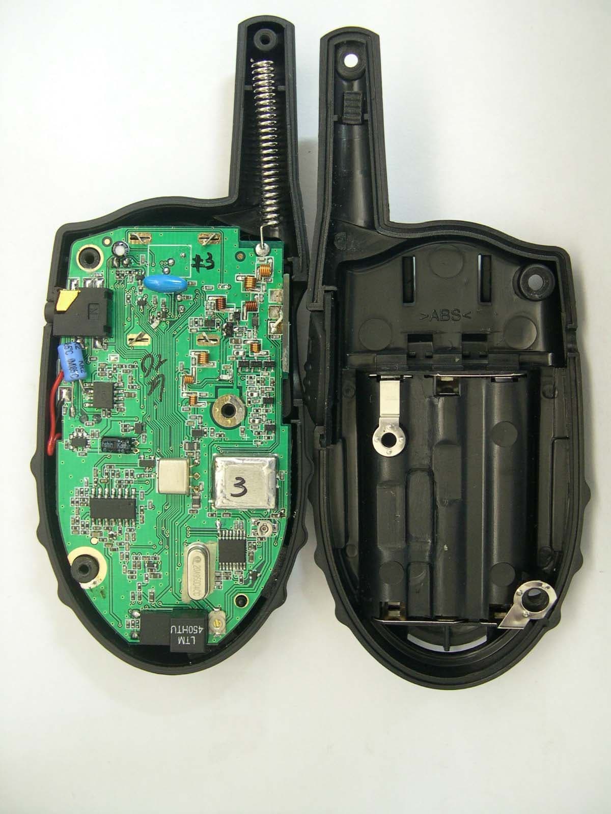
Click to zoom
Application Details
- Equipment Class
- FRF - Part 95 Family Radio Face Held Transmitter
- Date of Grant
- Nov 08, 2004
- Application Purpose
- Original Equipment
- Date of Application
- Nov 08, 2004
- Equipment Note
- FRS/GMRS COMBINATION
- Frequency Range
- 462.56250000 - 467.71250000
- Company
- Midland Radio Corporation
- Country
- United States
Documents & Files
Document Text
Text extracted from the exhibit documents filed with the FCC. Open a document above to read the original.
Users Manual
® The World in Communication “ A A A ” “ A A A ” “ A A A ” SCANMODE ® MIDLAND G4 22 CHANNEL GMRS/FRS TRANSCEIVER MIDLAND G4 is a new GMRS/FRS trans ceiver that may be used, without license, where GMRS/FRS frequencies are authorized (462.5500 - 467.7125 MHz). Main features: •Freq. 462.5500 - 467.7125 MHz • Channel spacing: 25kHz • 22 GMRS/FRS channels • Power 500mW ERP • Coverage up to 4-5 km • Batteries: AAAtype, rechargeable or alkaline • Alphanumeric LCD Display • VOX (hands-free transmission) • Channel Scan function • Battery life up to 35 hours (alkaline type) • Operating temperature from -20 o to +55 o • Weight 63 gms. • Size 53x89x28mm • Jack for audio accessories: 1pin, 2.5mm (SPKMIC) [7] • Jack for Wall Charger (CHG) [7] Specifications are subject to change without notice Battery compartment To open the battery compartment, hold the unit face down and slide the cover towards the bottom of the radio; then, insert 3 x AAAalkaline or rechargeable batteries. Content •1 MIDLAND G4 transceiver • 1 belt clip • User Manual LET’S COMMUNICATE! To turn radio on/off Hold the button [3] for 3 seconds. The radio beeps 3 times with different tones. The LCD[1] displays a “self test” message for 1 second, it will then indicate the last channel selected. Volume adjustment To adjust the volume level, push t/s[2] buttons until you reach the desired level. * * * * C C o o v v e e r r a a g g e e The maximum range is obtained during use in an open space. The only limitation to maximum possible range are environmental factors such as blockage caused by trees, buildings, or other obstructions. Inside a car or metallic construction, the range can be reduced. Channel selection Press the button [3] once and then the t/s[2] controls to select one of the 22 channels. To confirm the selection, push PTT[6] or wait for 5 seconds roughly. CHANNEL FREQ. RX/TX (MHz)CHANNEL FREQ. RX/TX (MHz) 01 462.5625 12 467.6625 02 462.5875 13 467.6875 03 462.6125 14 467.7125 04 462.6375 15 462.5500 05 462.6625 16 462.5750 06 462.6875 17 462.6000 07 462.7125 18 462.6250 08 467.5625 19 462.6500 09 467.5875 20 462.6750 10 467.6125 21 462.7000 Transmission For maximum speech clarity, hold the radio 4 to 10cm away from your mouth, keep the PTTbutton [6] pressed and speak into the unit. During transmission the display shows: Reception Simply release the PTTbutton [6]. When you receive a signal, display shows: Automatic power save MIDLAND G4 is supplied with an automatic current economy circuit. If the transceiver receives no signal for 7 seconds or longer the “power save function” automatically acti- vates. The battery life may increase by up to 50%. When the batteries are in need of charging, icon will be displayed: it is necessary to replace the alkaline batteries or recharge the Ni-Cd/NiMH ones. Jack CHG [7] External charger jack. Insert the original charger plug into the CHGjack [7]. We recom- mend use of the appropriate charger only. Attention:alkaline batteries cannot be recharged. Keypad lock Press and hold the SCAN[4] button for longer than 3 seconds: the dis- play will show Lo to confirm activation. PTT[6] will still be active. The display will show Lc everytime the buttons are pressed. To de-activate the Keypad lock, press and hold the SCAN [4] button for longer than 3 seconds: the display will show LF to confirm de-activation. KEYFUNCTIONS VOX: hands-free transmission VOX function activation Press the [3] key for two times. The display shows “VOX” blinking at the top on the right, and at the right side of the display, "oF" appears. Select “on” by means of t/s[2] buttons and push the PTT[6] key, or simply await 5 seconds for confirmation. Speak into the microphone [5]: the transmission is automatically activated. VOX function deactivatio n Press the [3] key for two times. The display shows “VOX” blinking at the top on the right, and at the right side of the display, “on” appears. Select "oF" by means of t/s[2] buttons and push the PTT[6] key, or simply await 5 seconds for confirmation. SCAN FUNCTION The SCAN mode monitors the busy channels. It is used to check the traffic radio on the 22 channels before transmitting and allows the unit to stop on a channel that someone is talking on. When the radio stops on a busy channel, the scan will resume after about 5 seconds. To enable SCAN: 1. Press the SCAN[4] key: channels will start scanning on the display [1]. 2. Press [2] buttons to skip the channels with a strong background noise. Transmission during the SCAN function At the PTT[6] pressure, the radio will transmit on the channel where the scan started. To deactivate this function, push the SCAN [4] key again. G4 7 11467.637522462.7250 t/s REV.A ENGLISH Use of GMRS radios within the United States requires a FCC GMRS license. An individual 18 years of age or older, who is not a representative of a foreign government is eligible to apply for a GMRS system license. You will need two forms from the FCC, FCC Form 159 and FCC From 605 Main From and Schedule F. You can find the forms online at http://www.fcc.gov/formpage.html, or call 1-800-418-3676. Background noise reduction (Squelch) In your MIDLAND G4 the background noise reduction device (squelch) is activated by default. GMRS LICENSE
External Photos
DSCN1467 (1280x960x16M jpeg)
Operational Description
G4 TECHNICAL DESCRIPTION Page 1 A). GENERAL DESCRIPTION The G4 radio is a self-contained transceiver unit with integral antenna intended for use as a general communication tool. It is designed to operate on all 22 channels allocated by the IC for the licensed FRS. The useable range, while dependent upon terrain and other radio propagation principles, is typically two miles. The G4 uses the maximum transmit power allowed to help ensure the maximum communication range. Features include: 22 FRS Channels, Digital Receive Volume Control, Channel Monitor, Page and LCD Display. The unit is equipped with an external Headset option connector. Three AAA alkaline batteries that are readily available in retail outlets supply operating power. An automatic power savings feature allows the typical standby battery life to extend to more than 3 days. B). FREQUENCY DETERMINING CIRCUITS The fundamental frequency for both the transmitter and the receiver local oscillators are controlled by a phase lock loop (PLL) circuit IC201 (Toshiba TB31202, or equipvalent). The frequency of operation of the FRS voltage controlled oscillator (VCO), composed of Q301 and Q302 operating in cascade is phase locked to a voltage controlled crystal reference (VCXO) operating at 20.95MHz (X202). The VCO is locked to the fundamental of the transmit signal in the transmit mode and is locked to the receive 1 st LO (Fundamental channel frequency minus 21.4MHz) in the receive mode. The crystal reference frequency is shared with the 2 nd LO of 20.95MHz. C). TRANSMITTER CIRCUITS The transmitter amplifies the 0 dBm signal from the VCO to approximately 26dBm that is fed to the antenna. The transmitter is a three stage amplifier composed of Q1,2,3,4 and Q5. The first two stages are operated class A and the final is operated class B in full saturation to help prevent unwanted amplitude modulation. The fundamental transmit signal is fed through an elliptical low pass filter (5-pole, 2 zero) in order to suppress the harmonics to below –50 dBc. The desired frequency modulation of the carrier is accomplished by modulating the current in the VCO directly with the microphone audio signal. The microphone audio is conditioned a hard clipper circuit (IC5B) to limit maximum deviation to +/- 2.5 kHz and a three-pole low pass or splatter filter at 2.8 kHz (IC5A). The low pass filter insures that the G4 TECHNICAL DESCRIPTION Page 2 occupied bandwidth of the FM modulated signal meets IC requirements under all input conditions. D). RECEIVER CIRCUITS The received signal from the antenna is band limited to 600MHz by the transmitter harmonic filter. The desired signal is fed to a low noise amplifier (LNA – Q6) centered from 460 to 470 MHz that provides approximately 10 dB of gain. The output of the LNA is filtered with a Band Pass filter (C41,L16,C43,L17,C15,L5) with pass-band of 460 to 470 MHz and stopband attenuation of 10 dB. The filtered receive signal is one input to the 1 st mixer (Q8), the other mixer input (1 st LO) is the output of the VCO at the desired channel frequency minus 10.7MHz. The output of the mixer is tuned to the 1 st IF of 10.7MHz. The 1 st IF is transformer coupled for impedance matching to a ceramic filter centered at 10.7MHz with a bandwidth of +/-230KHz. The filtered 1 st IF is fed to the 2 nd mixer input of the multi-function receiver IC (IC1). The 2 nd LO (10.25MHz) is generated by VCXO that is the reference frequency for the PLL. The 2 nd mixer output of 450 kHz is filtered through a 6 section ceramic filter that in combination with the 10.7MHz X-tal filter provides approximately 50 dB of adjacent channel attenuation. The 450 kHz 2 nd IF is then amplified, limited and fed to a quadrature detector for FM demodulation. The resulting audio output signal is bandpass filtered from 300 to 3 kHz (IC2) and amplified to provide 150mW of audio power (IC2). A squelch circuit is provided (IC1 pins 10 through 11) to mute the receiver noise under low signal conditions. The squelch circuit amplifies and detects noise in a narrow bandwidth at approximately 5 kHz. When the detected noise exceeds a threshold set to trigger at approximately 9 dB SINAD receive signal strength, the audio output is muted. E). TRANSMIT/RECEIVE SWITCH When the radio is in the transmit mode, pin diode switches D13 and D1 are both turned on (representing less than 0.7 ohms). D13 allows the transmit signal to pass to the antenna and D1 shorts one leg of a T matching network (L3, L15 and C4) to ground in the receive path. This results in a parallel tuned circuit high impedance being presented to the transmit signal so that the receive path does not load the transmit signal. In the receive mode, both D13 and D1 are off, resulting in the antenna signal being coupled into the receive LNA through the 50 ohm T matching network and the unwanted load of the transmit final amplifier is reduced to less than 1 pF by D1. F). RADIO CONTROL CIRCUIT A microprocessor (CPU1) is used to control the transceiver. User stimuli is provided through a tack switch for PTT (push to talk), along with the keypad for channel selection, channel monitor, receive volume, and page. Pressing G4 TECHNICAL DESCRIPTION Page 3 the PTT switch instructs CPU1 to switch to the transmit mode. This is accomplished by loading the proper channel counter information through a 3- wire serial link to the PLL IC (IC201), turning on power to the PLL and VCO, microphone and transmit audio circuits and the transmit RF amplifiers. Pressing the call switch causes the microcontroller to transmit a warbling tone for approximately 3 seconds on the current channel selected that is used to notify another person with FRS radio that you wish to communicate. Pressing the channel Up/Down buttons (active in receive mode only) instructs CPU1 to increment or decrement respectively the channel frequency by one channel from the channel previously selected. In receive mode the microcontroller periodically switches on the VCO and receiver p…
Text truncated - open the document above for the full version.
Test Report
THRUlab & EngineeringUGG ytXXW\SXXmsSGhjlG{ljouvG{v~lyG X`^TYYSn|yvTkvunGn|yvTn|Gzlv|sGrvylhG _XYYXW`\W\`m_XYYXW`\W\]GGgUG Test Report Product Name: GMRS/FRS Combination FCC ID:MMAG4 MODEL NO:G4 Applicant: Midland Radio Corporation. 1120 Clay St. North Kansan City, MO 64116 Date Receipt:11/03/2004 Date Tested: 11/02/2004 THRUlab & EngineeringUUGG ytXXW\SXXmsSGhjlG{ljouvG{v~lyG X`^TYYSn|yvTkvunGn|yvTn|Gzlv|sGrvylhG _XYYXW`\W\`m_XYYXW`\W\]GGgUG hwwspjhu{GaGtGyGjUG mjjGpkGGGGGGa MMAG4G ylwvy{GGGGa{oy|T[XXWWY G waGYGX`G TABLE OF CONTENTS LIST APPLICANT: Midland Radio Corporation. FCC ID :MMAG4 TEST REPORT PAGE 3......... GENERAL INFORMATION & TECHNICAL DESCRIPTION PAGE 4......... TECHNICAL DEACRIPTION & RF POWER OUTPUT PAGE 5......... MOD. CHARACTERISTICS & AUDIO FREQUENCY RESPONSE GRAPH PAGE 6......... MODULATION LIMITING GRAPH – 300 Hz PAGE 7......... MODULATION LIMITING GRAPH – 1000 Hz & 2500 Hz PAGE 8......... AUDIO LOW PASS FILTER GRAPH PAGE 9......... OCCUPIED BANDWIDTH PAGE 10.........OCCUPIED BANDWIDTH PLOT PAGE 11.........SPURIOUS EMISSIONS AT ANTENNA TERMINALS PAGE 12.......UNWANTED RADIATION - GMRS PAGE 13.......UNWANTED RADIATION - FRS PAGE 14.......METHOD OF MEASURING RADIATED SPURIOUS EMISSIONS PAGE 15.......FREQUENCY STABILITY PAGE 16....LIST OF EMC TEST EQUIPMENT EXHIBITS CONTAINING: EXHIBIT 1..... FCC ID LABEL SAMPLES EXHIBIT 2..... LABEL LOCATION EXHIBIT 3..... EXTERNAL PHOTOGRAPHS EXHIBIT 4..... INTERNAL PHOTOGRAPHS EXHIBIT 5..... BLOCK DIAGRAM EXHIBIT 6..... SCHMATICS EXHIBIT 7..... USER’S MANUAL EXHIBIT 8..... THEORY OF OPERATION EXHIBIT 9..... ALIGNMENT PROCEDURE EXHIBIT 10... PARTS LIST EXHIBIT 11... TEST SET UP PHOTO THRUlab & EngineeringUUGG ytXXW\SXXmsSGhjlG{ljouvG{v~lyG X`^TYYSn|yvTkvunGn|yvTn|Gzlv|sGrvylhG _XYYXW`\W\`m_XYYXW`\W\]GGgUG hwwspjhu{GaGtGyGjUG mjjGpkGGGGGGa MMAG4G ylwvy{GGGGa{oy|T[XXWWY G waGZGX`G GENERAL INFORMATION REQUIRED FOR CERTIFICATION 2.1033 (c) (1) (2) MidLand Radio Corporation. will manufacture the FCCID: MMAG4 GMRS/FRS COMBINATION TRANSCEIVER in quantity, for use under FCC RULES PART 95. MidLand Radio Corporation. -1120 Clay St. North Kansas City, MO 64116 2.1033 (c) TECHNICAL DESCRIPTION 2.1033 (c) (3) Instruction book. A draft copy of the instruction manual is included as EXHIBIT 7. 2.1033 (c) (4) Type of Emission : 10K5F3E 95.631 Bn=2M+2DK M = 3000 D = 2.25k Bn =2(3000) + 2(2250) = 10.5k GMRS Authorized Bandwidth:20.0kHz 2.1033 (c) (5) GMRS Frequency Range: 1. 462.5500 13. 462.7000 95.6212. 462.5625 14. 462.7125 3. 462.5750 15. 462.7250 4. 462.5875 16. 467.5500 5. 462.6000 17. 467.5750 6. 462.6125 18. 467.6000 7. 462.6250 19. 467.6250 8. 462.6375 20. 467.6500 9. 462.6500 21. 467.6750 10. 462.6625 22.467.7000 11. 462.6750 23. 467.7250 12. 462.6875 FRS Authorized Bandwidth:12.5kHz 2.1033(c)(5) FRS Frequency Range: 1. 462.5625 8. 467.5625 95.627 2. 462.5875 9. 467.5875 3. 462.6125 10. 467.6125 4. 462.6375 11. 467.6375 5. 462.6625 12. 467.6625 6. 462.6875 13. 467.6875 7. 462.7125 14. 467.7125 MHz 2.10311c)(6)(7) RF power is measured by the substitution method as 2.1046(a) outlined in TIA/EIA - 603. With a nominal battery voltage of[U\}kjand the transmitter properly adjusted the RF output measures: GMRS : 0.115 Watts Max,(1CH) FRS :0.144 Watts Max(11CH) The GMRS does Not transmit the higher power on the FRS frequencies THRUlab & EngineeringUUGG ytXXW\SXXmsSGhjlG{ljouvG{v~lyG X`^TYYSn|yvTkvunGn|yvTn|Gzlv|sGrvylhG _XYYXW`\W\`m_XYYXW`\W\]GGgUG hwwspjhu{GaGtGyGjUG mjjGpkGGGGGGa MMAG4G ylwvy{GGGGa{oy|T[XXWWY G waG[GX`G 2.1033(c)(6)(7) FRS Power Output shall not exceed 0.50 Watts effective 95.639 radiated power. There can be no provisions for 95.649 Increasing the power or varying the power. 2.1033(c)(8) DC Voltages and Current into Final Amplifier: FINAL AMPLIFIER ONLY FOR GMRS POWER SETTING INPUT POWER: (4.5V)(0.260A)=1.17 Watts. FOR FRS POWER SETTING INPUT POWER: (4.5V)(0.260A)=1.17 Watts. 2.1033(c)(9) Tune-up procedure. The tune-up procedure is included as EXHIBIT # 9. 2.1033(c)(10) Complete Circuit Diagrams: The circuit diagram is included as EXHIBIT 6 of this report. The block diagrams are included as EXHIBIT 5 of this report. 2.1033(c)(11) A photograph or a drawing of the equipment identification label is included as exhibit No. 1. 2.1033(c)(12) Photographs(8"X10") of the equipment of sufficient clarity to reveal equipment construction and layout, including meters, labels for controls, including any view under shields. See exhibits 3-4. 2.1033(c)(13) Digital modulation is not allowed. 2.1033(c)(14) The data required by 2.1046 through 2.1057 is submitted below. 2.1046(a) RF power output. The test procedure used was TIA/EIA-603. THRUlab & EngineeringUUGG ytXXW\SXXmsSGhjlG{ljouvG{v~lyG X`^TYYSn|yvTkvunGn|yvTn|Gzlv|sGrvylhG _XYYXW`\W\`m_XYYXW`\W\]GGgUG hwwspjhu{GaGtGyGjUG mjjGpkGGGGGGa MMAG4G ylwvy{GGGGa{oy|T[XXWWY G waG\GX`G THRUlab & EngineeringUUGG ytXXW\SXXmsSGhjlG{ljouvG{v~lyG X`^TYYSn|yvTkvunGn|yvTn|Gzlv|sGrvylhG _XYYXW`\W\`m_XYYXW`\W\]GGgUG hwwspjhu{GaGtGyGjUG mjjGpkGGGGGGa MMAG4G ylwvy{GGGGa{oy|T[XXWWY G waG]GX`G 2.1047 (a) (b) Modulation characteristics : AUDIO FREQUENCY RESPONSE The audio frequency response was measured in ac- cordance with TIA/EIA Specification 603. The audio frequency response curve is shown on the next page. The audio signal was fed into a dummy microphone Circuit and into the microphone connector. The Input required to produce 30 percent modulation Level was measured. See plot below. AUDIO FRQUENCY RESPONSE PLOT GOES HERE Audio Frequency Response -30 -20 -10 0 10 01002003004005006007008009001k1.5k2k2.5k3k4k Frequency Hz Attenuation dB THRUlab & EngineeringUUGG ytXXW\SXXmsSGhjlG{ljouvG{v~lyG X`^TYYSn|yvTkvunGn|yvTn|Gzlv|sGrvylhG _XYYXW`\W\`m_XYYXW`\W\]GG…
Text truncated - open the document above for the full version.
Test Setup Photos
THRUlab & EngineeringUUGG ytXXW\SXXmsSGhjlG{ljouvG{v~lyG X`^TYYSn|yvTkvunGn|yvTn|Gzlv|sGrvylhG _XYYXW`\W\`m_XYYXW`\W\]GGgUG hwwspjhu{GaGtGyGjUG mjjGpkGGGGGGa MMAG4G ylwvy{GGGGa{oy|T[XXWWY G waGX`GX`G
Contact Information
Applicant
Butch Rittmann(Director of Operations)
Test Firm
Thru Lab & EngineeringK. Kang
Technical Specifications
| # | Rule Parts | Frequency Range | Power Output | Emission | Tolerance |
|---|---|---|---|---|---|
| 2 | 95B | 462.5625 MHz - 467.7125 MHz | 144.00 mW | 10K5F3E | 2.5 ppm |
Other Applications from Midland Radio Corporation

MMAMXMC95
Jun 10, 2026Wireless Bluetooth Microphone
Equipment Class
JAB - Part 15 Class B Digital Device
MMAMXT295
Jun 08, 2026GMRS Radio
Equipment Class
TNF - Licensed Non-Broadcast Transmitter Held to Face
MMACLIPTALK
Apr 27, 2026Transceiver
Equipment Class
DTS - Digital Transmission System
MMABR200S
Jan 13, 2026BUSINESS BAND TWO-WAY RADIO
Equipment Class
TNF - Licensed Non-Broadcast Transmitter Held to Face
MMAGXT67
Oct 29, 2023GMRS RADIO
Equipment Class
TNF - Licensed Non-Broadcast Transmitter Held to Face