MMALXT300FRS/GMRS Transceiver
Midland Radio Corporation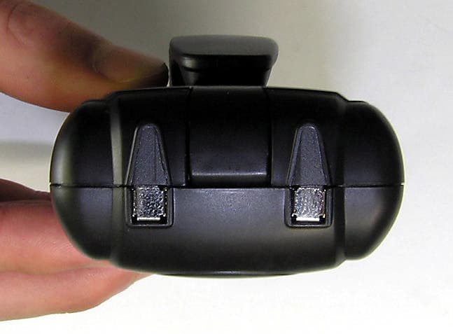
Click to zoom
Application Details
- Equipment Class
- FRF - Part 95 Family Radio Face Held Transmitter
- Date of Grant
- Feb 16, 2006
- Application Purpose
- Original Equipment
- Date of Application
- Feb 15, 2006
- Equipment Note
- FRS/GMRS Transceiver
- Frequency Range
- 462.55000000 - 462.72500000
- Company
- Midland Radio Corporation
- Country
- United States
Documents & Files
Document Text
Text extracted from the exhibit documents filed with the FCC. Open a document above to read the original.
Users Manual
POSGEN USER Operating manual of FRS/GMRS Transceiver (LXT-300) POSGEN FCC Operation Guide This device complies with part 15 of the FCC Rules. Operation is subject to the following two conditions: (1) This device may not cause harmful interference, and (2) This device must accept any interference received, including interference that may cause undesired operation. ’ Any changes or modifications to the equipment not expressly approved by the party responsible for compliance could void user’s authority to operate the equipment. POSGEN LXT-300 LCD Display ICONS on LCD Display 1. Large Segment Display : Indicates the main channel number in use from 1-22. 2. TX/RX Indicator : Indicates the status of TX and RX 3. Key Tone : The icon appears when the Key Tone function is selected. You can hear beep-tone with this function when Key tone is selected. 4. Roger Beep : Indicates the Roger beep is activated. The roger beep is TX confirmation beep sound. 5. Key Lock : Displays Key lock function is activated. 6. Low Battery lndicator: Indicates the LOW battery status. 8. Scan : Displays when the Scan is activated. 9. Low (power) Indicator : Indicates the RF power is automatically 500mW in FRS channels. Powering the transceiver: Your LXT-300 radio transceiver operates with either four AAA batteries or the included NiMH battery pack. POSGEN Installing the batteries: To install the batteries ; 1. Un-lock the locking knob, and remove the battery cover. 2. Insert four AAA batteries or battery pack, observing the polarity as shown. Installing the batteries incorrectly will prevent the unit from operating and can damage the unit. 3. Return the battery cover, and lock the locking knob. The following guidelines will improve performance and provide longer operating times for the LXT-320/300 1. Do not mix old and new batteries 2. The use of alkaline-type batteries is recommended to provide the longest operating time. 3. Do not mix alkaline, standard or rechargeable batteries. 4. If the unit is not to be used for an extended period of time, remove the batteries. Old or leaking batteries can cause damage to the unit and will void the warranty. POSGEN Operation Power On/Off Press and hold the power on/off button for 2 second. You will hear a confirming beep tone to indicate the unit is on. To turn the unit off, press and hold the button for 2 second. Adjusting the Volume With the unit powered on and in the standby mode, press the Up/Down arrow button to control listening volume increase or decrease. The display will indicate the current volume level by the small number in the icon. Talking and Listening To communicate, all radios in your group should be set to the same channel. Press and hold the PTT button and speak in a normal voice into the microphone. The TX icon appears on the LCD Display during transmitting. To receive messages, release PTT button. The RX icon appears on the display when your radio is receiving transmission. Menu/Monitor Button This button is used to select functions in Menu button or activate monitor function. Long pressing (for 2 second) of this button will activate the Monitor feature. Short pressing of this button will activate mode selection. When you press this button momentary, it goes into Main channel selection -> Beep tone on/off selection -> Roger beep on/off selection -> Call selection mode in order. Monitor (Open Squelch Function) This radio equipped with auto-squelch which automatically shuts off weak transmissions or unwanted noise due to terrain conditions or if you have reached range limit. Auto squelch can be temporarily removed to allow all signals to enter (maximum range extend). Press and hold the Menu/Monitor button for 2 second to operate this feature and to allow all signals enter. To return to normal operation, press and hold the Mode/Monitor button for 2 second again. Push To Talk (PTT) Button / Call Pressing and holding this button will allow you to speak to any transceiver that is set to the same channel and privacy code setting as yours. Hold the transceiver approximately 1 to 2 inches from your face as you speak into the built in microphone. After you have finished speaking, release the PTT Button to allow reception of incoming signals. It is not possible to transmit and receive at the same time. The PTT Button can also be used as a two-way call ringer. Pressing this button twice quickly will call another party on the same channel. Main Channel Selection ln the standby mode, press Mode/Monitor button once momentary. Then Main channel segment will blinking on LCD display. Press the Up/Down arrow button to select desired channel. To save the selected channel, press the PTT button. Beep Tone In the standby mode, press the Menu/Monitor button 4 times. Then it goes to Beep Tone selection mode. Pressing the Up/Down arrow button, you can select beep tone on or off. To exit and go to standby mode directly, press the PTT button momentary. POSGEN Roger Beep In the standby mode, press the Menu/monitor button 5 times. Then it goes to Roger Beep selection mode. Pressing the Up/Down arrow button, you can select on or off of the roger beep tone. To exit and go to standby mode, press the PTT button momentary. Call Selection In the standby mode, press the Mode/Monitor button 6 times. Then it goes to Call melody selection mode. Pressing the Up/Down arrow button, you can select 3 different call tones. Select your desired melody and press PTT button to goes to standby mode. External Speaker (SPK)/Microphone (MIC) Jacks This set of jacks accepts an headset/microphone connector for hand-free operation. 1. Insert the plugs into the SPK/MIC jacks. 2. Place the earbud into your ear, and adjust the Mic into your desired position. Channel Scan Operation This feature allows you to monitor all main channels automatically for valid signals While scanning, you can transmit and receive. When a signal is received, the scan is interrupted. Press Scan button to resume scanning. To enable the channel…
Text truncated - open the document above for the full version.
Cover Letter(s)
Mike Kuo From: Kwon, James (Gunpo) [[email protected]] Sent: Wednesday, February 15, 2006 9:56 PM To: Mike Kuo Cc: Helen Zhao; Ham, Denny (Gunpo); Jeong, Feel (Gunpo) Subject: RE: Midland Radio Corporation, FCC ID: MMALXT300, Assessment NO.: AN06T5503, Notice#1 2/16/2006 Hi Mike, Pls find my reply at below. Thanks and have a nice day. ===================================================== James Kwon ( [email protected] ) / Wireless Division Tel : 82-31-428-5740 Fax: 82-31-427-2370 Mobile : 82-11-9788-0485 SGS Testing Korea Co., Ltd. (www.sgstesting.co.kr) Add: 18-34, Sanbon-Dong, Gunpo-City, Kyunggi-Do, Korea ===================================================== -----Original Message----- From: Mike Kuo [mailto:[email protected] ] Sent: Wednesday, February 15, 2006 6:38 PM To: Kwon, James (Gunpo) Subject: FW: Midland Radio Corporation, FCC ID: MMALXT300, Assessment NO.: AN06T5503, Notice#1 Question #1: Emission designator is listed as 11K0F3E, please justify the necessary bandwidth by using Cardson rule ( 2M+2DK). Refer section 2.202 for guideline. [James] We justified Emission designator, and we added this contents on item #13 of test report. Page number is changed accordingly. So I uploaded "revised 'test report, external photos, internal photos, and test set-up photo' " via your e-filing system. Question #2: User Manual : Missing GMRS licensing information and this device is equipped with body worn accessories and face-held operation. By indicating the device needs to maintain 20 cm separation distance during normal operation can not be achieved by the user. Please consider to change / add the following statement in the user manual. This device complies with Part 15 of the FCC Rules. Operation is subject to the following two conditions : (1) this device does not cause harmful interference, and (2) this radio must accept any interference that may cause undesired operation. Exposure To Radio Frequency Energy To maintain compliance with FCC¡¦s RF exposure guidelines, for body-worn operation, this radio has been tested and meets the FCC RF exposure guidelines when used with Midland Radio Corp. accessories supplied or designated for this product. Use of other accessories may not ensure compliance with FCC RF exposure guidelines. For best transmission result, always keep your mouth 2-3 inches from the microphone and speak slowly in a normal voice. IMPORTANT NOTICE, FCC LICENSE REQUIRED FOR GMRS OPERATION The LXT300 operates on GMRS (General Mobile Radio Service) frequencies which require an FCC (Federal Communications Commission) license. You must be licensed prior to operating on channels 1 - 7 or 15 - 22, which comprise the GMRS channels of the LXT300. Serious penalties could result for unlicensed use of GMRS channels, in violation of FCC rules, as stipulated in the Communications Act's Sections 501 and 502 (amended). You will be issued a call sign by the FCC which should be used for station identification when operating the radio on GMRS channels. You should also cooperate by engaging in permissible transmissions only, avoiding channel interference with other GMRS users, and being prudent with the length of their transmission time. To obtain a license or ask questions about the license application, contact the FCC at 1-886-CALL FCC or go to the FCC's website: www.fcc.gov/wtb/prs/genmbl.html [James] We changed user manual accordingly, and uploaded also. Question #3: In the EMC test report, only channel 17/GMRS with 1 W rate power and Channel 8/FRS with 0.5 W rate output power were selected during the tests. Since the measured ERP output power at channel 17/GMRS is 0.54W (ERP ) which is higher than FRS allowed output power (0.5 W ERP ), there is no evidence that this device can operate at all FRS channel. By reading the radio specification, during GMRS mode, there is low and high power setting to switch between GMRS and FRS mode. Please select one of channel between channel 1 to channel 7 with low output power setting to show FRS mode in channel 1 to 7 can comply with output power requirement. [James] ch8-ch14 is used only for FRS purpose. The output power is fixed one, so if user select ch8-ch14, the output power goes into max 0.5W. Also if user select ch1-7 and ch15-22, the output power goes into max 1.0W. As you can see from "Radio specification" file, there is a frequency table, but we confirm that there is no switch function. If this device can only channel 8 - 14 is designed for FRS operation but not any other channel, then you do not need to do additional tests and the grant will be listed as the following : Please confirm: 462.55- 462.7250 MHz, Part 95A, 0,54 W ( ERP ) 467.5625 - 467.7125 MHz, Part 95B, 0,275 W ( ERP ). [James] Correct. Best Regards Mike Kuo The items indicated above must be submitted before processing can continue on the above referenced application. Failure to provide the requested information within 30 days of the original e-mail date may result in application dismissal and forfeiture of the filing fee. Also, please note that partial responses increase processing time and should not be submitted. Any questions about the content of this correspondence should be directed to the e-mail address listed below the name of the sender. Information in this email and any attachments is confidential and intended solely for the use of the individual(s) to whom it is addressed or otherwise directed. Please note that any views or opinions presented in this email are solely those of the author and do not necessarily represent those of the Company. Finally, the recipient should check this email and any attachments for the presence of viruses. The Company accepts no liability for any damage caused by any virus transmitted by this email. All SGS services are rendered in accordance with the applicable SGS conditions of service available on request and accessible at http://www.sgs.com/terms_and_conditions.htm 2/16/2006
Cover Letter(s)
POSGEN Posgen Communications Co., Ltd. Suite 801, Daeryung Techno Town-3, Gasan-Dong, Kumchun-Gu, Seoul, Korea. (T) +82-2-2107-7992 (F) +82-2-2107-7994 To: Tim Harrington ([email protected]) Date: 7/28/2006 /FCC Equipment Authorization Branch From: Dae-Sung Ha ([email protected]) /Lab manager of R&D Center of Posgen CC: David Kingsolver ([email protected]) Mike Kuo ([email protected]) Applicant : Midland Radio Corporation FCC ID : MMALXT300 Correspondence Reference Number : 30479 731 Confirmation Number : TC292769 Subject : Reply on Audit dated 7/26/2006 Question : Please explain compliance with 47 CFR 95.651 Crystal Control Required for GMRS equipment authorization. Reply : Dear Sir, Posgen is design & R&D center of LXT-300 model owning Daxian Telecommunication Ltd. (=manufacturer of this model) which is located in China. “The compliance with 47 CFR 95.651 Crystal Control Required“ is already explained in “Theory of operation“, which is submitted when new submission same as below : PLL Frequency Synthesizer ( IC301 ) The PLL synthesizer of the LXT-300 consists of the signal loop PLL circuit with the reference of 6.25KHz. The IC301 PLL IC includes all the functions such as the POSGEN Posgen Communications Co., Ltd. Suite 801, Daeryung Techno Town-3, Gasan-Dong, Kumchun-Gu, Seoul, Korea. (T) +82-2-2107-7992 (F) +82-2-2107-7994 reference oscillator, the driver, the phase detector, the lock detector, and the programmable divider. At the reference oscillator, the 21.25MHz TCXO of the TCXO is connected to the pin 11 of the IC301 to oscillate the frequency of 21.25MHz. The TCXO(21.25MHz) is the temperature compensation circuit to maintain the frequency within the allowable error range even under a low temperature of -30 °C. The phase detectors send out the output power to the loop filter through 3 pin of the IC301. If the oscillation frequency of the VCO is low compared to the reference frequency, the phase detector sends out the output power in positive pulse. If the oscillation frequency of the VCO is high, phase detector sends out the output power in negative pulse. Therefore, the VCO can maintain the frequency set. The programmable divider maintains the desired frequency with the control from the CPU. The dividing ratio, "N" to oscillate the desired frequency is as below : N = VCO oscillation frequency / reference frequency If the desired frequency is 462.5625MHz N = 462.5625MHz / 0.00625MHz = 74802 If you have further questions feel free to contact me. Regards, Dae-Sung Ha /Lab manager of R&D Center /Posgen
External Photos
Report File No. : STROR-06-008 Date of Issue : Feb. 02. 2006 Page : 25 of 30 The results shown in this test report refer only to the sample(s) tested unless otherwise stated. This test report cannot be reproduced, except in full, without prior written permission of the Company. Tel. +82 31 428 5700 / Fax. +82 31 427 2371 www.sgstesting.co.kr 15. Attachment B – Photos of the EUT l Front View of EUT l Rear View of EUT Report File No. : STROR-06-008 Date of Issue : Feb. 02. 2006 Page : 26 of 30 The results shown in this test report refer only to the sample(s) tested unless otherwise stated. This test report cannot be reproduced, except in full, without prior written permission of the Company. Tel. +82 31 428 5700 / Fax. +82 31 427 2371 www.sgstesting.co.kr l Left View of EUT l Right View of EUT Report File No. : STROR-06-008 Date of Issue : Feb. 02. 2006 Page : 27 of 30 The results shown in this test report refer only to the sample(s) tested unless otherwise stated. This test report cannot be reproduced, except in full, without prior written permission of the Company. Tel. +82 31 428 5700 / Fax. +82 31 427 2371 www.sgstesting.co.kr l Top View of EUT l Bottom View of EUT
ID Label/Location Info
FCC ID LABEL 1. FCC ID label drawing 2. FCC ID label location
Internal Photos
Report File No. : STROR-06-008 Date of Issue : Feb. 02. 2006 Page : 28 of 30 The results shown in this test report refer only to the sample(s) tested unless otherwise stated. This test report cannot be reproduced, except in full, without prior written permission of the Company. Tel. +82 31 428 5700 / Fax. +82 31 427 2371 www.sgstesting.co.kr l Inner View of EUT Report File No. : STROR-06-008 Date of Issue : Feb. 02. 2006 Page : 29 of 30 The results shown in this test report refer only to the sample(s) tested unless otherwise stated. This test report cannot be reproduced, except in full, without prior written permission of the Company. Tel. +82 31 428 5700 / Fax. +82 31 427 2371 www.sgstesting.co.kr l View of PCB(with shield can) l View of PCB(without shield can) Report File No. : STROR-06-008 Date of Issue : Feb. 02. 2006 Page : 30 of 30 The results shown in this test report refer only to the sample(s) tested unless otherwise stated. This test report cannot be reproduced, except in full, without prior written permission of the Company. Tel. +82 31 428 5700 / Fax. +82 31 427 2371 www.sgstesting.co.kr l Bottom View of PCB (with shield can) l Bottom View of PCB (without shield can)
Parts List/Tune Up Info
POSGEN Antenna Specification Page 2 Beam-pattern.(Azimuth) Page 3 Beam-pattern.(Elevation)
Parts List/Tune Up Info
9. Alignment instructions WARNING TRANSMITTER RECEIVER
RF Exposure Info
SGS TESTING KOREA TEST – REPORT SAR Compliance Test Report Test report no.: STROS-06-002 SAR SGS TESTING KOREA Co., Ltd. 18-34, Sanbon-dong, Gunpo-si, Gyeonggi -do, Korea, 435-041 PHONE +82 31 428 5700 FAX +82 31 427 2371 Report File No. : STROS-06-002 Date of Issue: February 1, 2006 Page : 1 of 68 SGS Testing Korea Co., Ltd. 18-34, Sanbon-dong, Gunpo-si, Gyeonggi-do, Korea, 435-041 Tel. +82 31 428 5700 / Fax. +82 31 427 2371 http://www.sgstesting.co.kr TABLE OF CONTENTS 1 1.1 1.2 1.3 1.4 1.5 1.6 1.7 General information Notes Testing laboratory Details of approval holder Manufacturer Test item Test results Test standards 2 2.1 2.2 2.3 2.4 2.5 2.6 2.7 2.8 2.9 Technical test Summary of test results Test environment Test equipment utilized Definitions Measurement system description Test system specification Measurement procedure Reference positions for handheld radio transmitters Measurement uncertainty 3 3.1 3.2 4 5 6 Tissue and system verification Tissue verification System verification Test Results References Appendix Report File No. : STROS-06-002 Date of Issue: February 1, 2006 Page : 2 of 68 SGS Testing Korea Co., Ltd. 18-34, Sanbon-dong, Gunpo-si, Gyeonggi-do, Korea, 435-041 Tel. +82 31 428 5700 / Fax. +82 31 427 2371 http://www.sgstesting.co.kr 1 General Information 1.1 Notes The purpose of conformity testing is to increase the probability of adherence to the essential requirements or conformity specifications, as appropriate. The complexity of the technical specifications, however, means that full and thorough testing is impractical for both technical and economic reasons. Furthermore, there is no guarantee that a test sample which has passed all the relevant tests conforms to a specification. The existence of the tests nevertheless provides the confidence that the test sample possesses the qualities as maintained and that is performance generally conforms to representative cases of communications equipment. The test results of this test report relate exclusively to the item tested as specified in 1.5. The test report may only be reproduced or published in full. Reproduction or publication of extracts from the report requires the prior written approval of the SGS Testing Korea. I attest to the accuracy of data. All measurements reported herein were performed by me or were made under my supervision and are correct to the best of my knowledge and belief. I assume full responsibility for the completeness of these measurements and vouch for the qualification of all persons taking them. Tester: January 23, 2006 Elvin Lee Date Name Signature Technical responsibility for area of testing: February 1, 2006 Albert Lim Date Name Signature Report File No. : STROS-06-002 Date of Issue: February 1, 2006 Page : 3 of 68 SGS Testing Korea Co., Ltd. 18-34, Sanbon-dong, Gunpo-si, Gyeonggi-do, Korea, 435-041 Tel. +82 31 428 5700 / Fax. +82 31 427 2371 http://www.sgstesting.co.kr 1.2 Location of Testing laboratory SGS Testing Korea Co., Ltd. 18-34, Sanbon-dong, Gunpo-si, Gyeonggi-do Korea Telephone Fax : +82 31 428 5700 : +82 31 427 2371 1.3 Details of approval holder Name Address Country Telephone Fax Contact E-Mail Midland Radio Corporation 1120 Clay Street, North Kansas City, Missouri, USA 64116 USA 816 241 8500 816 241 5713 David Kingsolver [email protected] 1.4 Manufacturer: (if applicable) Name Street Town Country : Daxian Telecommunication Ltd. : No.2 industrial Area, Tangxiayong, Songgang : Shenzhen City : China Report File No. : STROS-06-002 Date of Issue: February 1, 2006 Page : 4 of 68 SGS Testing Korea Co., Ltd. 18-34, Sanbon-dong, Gunpo-si, Gyeonggi-do, Korea, 435-041 Tel. +82 31 428 5700 / Fax. +82 31 427 2371 http://www.sgstesting.co.kr 1.5 Test item FCC ID Description of test item Type identification Serial number Device category :MMALXT300 :Family Radio Face Held Transmitter (GMRS/FRS Combination) :LXT-300 : 512000006 : FRS/GMRS TRANSCEIVER Technical data Tx Frequency range (GMRS) Tx Frequency range (FRS) Rx Frequency range (GMRS) Rx Frequency range (FRS) Max. Conducted RF output power Power supply Antenna Tx Antenna Rx Antenna type : 462.5500 – 462.7250 MHz : 467.5625 – 467.7125 MHz : 462.5500 – 462.7250 MHz : 467.5625 – 467.7125 MHz : 1.0W - GMRS : 0.5W - FRS : 1.5 Vdc battery X 4 : external : external : Permanently Attached 1.6 Test Results Max. SAR Measurement: 0.635 W/kg (averaged over 1 gram) This EUT has been shown to be capable of compliance for localized specific absorption rate (SAR) for uncontrolled environment/general population exposure limits specified in ANSI/IEEE Std. C95.1-1992 and had been tested in accordance with the measurement procedures specified in FCC/OET Bulletin 65 Supplement C (2001) and IEEE Std. 1528-200X(Draft 6.5, January 2002). 1.7 Test standards Standards : - IEEE Std. 1528-200X (Draft 6.5, January 2002) FCC Rule Part(s) : - FCC OET Bulletin 65, Supplement C, Edition 01-01 Report File No. : STROS-06-002 Date of Issue: February 1, 2006 Page : 5 of 68 SGS Testing Korea Co., Ltd. 18-34, Sanbon-dong, Gunpo-si, Gyeonggi-do, Korea, 435-041 Tel. +82 31 428 5700 / Fax. +82 31 427 2371 http://www.sgstesting.co.kr 2 Technical test 2.1 Summary of test results Classification Uncontrolled environment/general population X Controlled exposure/occupational environment Applicable Configuration Handset (Head) Handset (Held to face) X Handset (Body) Headset (Head) Body Worn Equipment X EUT complies with the RF radiation exposure limits of the FCC as shown by the SAR measurement results. These measurements are taken to simulate the RF effects exposure under worst -case conditions. The EUT complies with the requirements in respect to all parameters subject to the test. The test results and statements relate only to the item(s) tested. Please note that the absorption and distribution of electromagnetic energy in the body are very complex phenomena that depend on the mass, shape, and size of the body, the orientation of the body with respect to the field vectors, and t…
Text truncated - open the document above for the full version.
Test Report
Report File No. : STROR-06-008 Date of Issue : Feb. 02. 2006 Page : 1 of 30 The results shown in this test report refer only to the sample(s) tested unless otherwise stated. This test report cannot be reproduced, except in full, without prior written permission of the Company. Tel. +82 31 428 5700 / Fax. +82 31 427 2371 www.sgstesting.co.kr TEST REPORT FCC Rules Part 95, Part 2 Equipment Under Test : FRS/GMRS TRANSCEIVER Model No. : LXT-300 Serial No. : - Applicant : Midland Radio Corporation Manufacturer : Daxian Telecommunication Ltd. Date of Test(s) : 2006. 01. 16 ~ 2006. 01.31 Date of Issue : 2006. 02. 02 In the configuration tested, the EUT complied with the standards specified above. Remarks: This report details the results of the testing carried out on one sample, the results contained in this test report do not relate to other samples of the same product. The manufacturer should ensure that all products in series production are in conformity with the product sample detailed in this report. This report may only be reproduced and distributed in full. If the product in this report is used in any configuration other than that detailed in the report, the manufacturer must ensure the new system complies with all relevant standards. Any mention of SGS Testing Korea Co., Ltd. or testing done by SGS Testing Korea Co., Ltd. in connection with distribution or use of the product described in this report must be approved by SGS Testing Korea Co., Ltd. in writing. Report File No. : STROR-06-008 Date of Issue : Feb. 02. 2006 Page : 2 of 30 The results shown in this test report refer only to the sample(s) tested unless otherwise stated. This test report cannot be reproduced, except in full, without prior written permission of the Company. Tel. +82 31 428 5700 / Fax. +82 31 427 2371 www.sgstesting.co.kr VERIFICATION OF COMPLIANCE Applicant : Midland Radio Corporation Kind of Product : FRS / GMRS Transceiver Brand Name : MIDLAND Model Name : LXT-300 Model Difference : - Report File No. : STROR-06-008 Date of test : Jan. 16, 2006 ~ Jan. 31, 2006 Receiver EUT : - APPLICABLE STANDARDS STANDARD TEST RESULT FCC RULES Part 95, Part 2 Complied The above equipment was tested by SGS Testing Korea Co., Ltd. for compliance with the requirements set forth in the FCC Rules Part95, Part2. The results of testing in this report apply to the product system that was tested only. Other similar equipment will not necessarily produce the same results due to production tolerance and measurement uncertainties. Tested By: Date Feb. 02, 2006 Feel Jeong Approved By Date Feb. 02, 2006 Albert Lim Report File No. : STROR-06-008 Date of Issue : Feb. 02. 2006 Page : 3 of 30 The results shown in this test report refer only to the sample(s) tested unless otherwise stated. This test report cannot be reproduced, except in full, without prior written permission of the Company. Tel. +82 31 428 5700 / Fax. +82 31 427 2371 www.sgstesting.co.kr INDEX CONTENTS Page 1. General Description of EUT ..................................................... 4 2. General Information of EUT ..................................................... 4 3. Test Procedure ..................................................................... 5 4. Test Equipment List ............................................................... 9 TEST RESULT 5. Output Power Conducted ......................................................... 10 6. Radiated Spurious Emissions .................................................... 11 7. Conducted Spurious Emissions .................................................. 12 8. Occupied Bandwidth ............................................................... 16 9. Audio Frequency Response ....................................................... 17 10. Audio Low Pass Filter Frequency Response .................................... 18 11. Modulation Limited ................................................................ 19 12. Frequency Stability ................................................................. 21 13. The Emission Designator ......................................................... 23 14. Attachment A – Photo of the Test Setup ......................................... 24 15. Attachment B – Photos of the EUT ............................................. 25 Report File No. : STROR-06-008 Date of Issue : Feb. 02. 2006 Page : 4 of 30 The results shown in this test report refer only to the sample(s) tested unless otherwise stated. This test report cannot be reproduced, except in full, without prior written permission of the Company. Tel. +82 31 428 5700 / Fax. +82 31 427 2371 www.sgstesting.co.kr 1. General Description of EUT The Midland Radio Corporation LXT-300 FRS/GMRS Transceiver is a self-contained FRS/GMRS transceiver unit intended for use as a general communication tool. Per the FCC definition: GMRS is a land mobile radio service available to persons for short distance two-way communications to facilitate the activities of licensees and their immediate family members. The LXT-300 model has 22 channels of which channels 1-7 share the FRS channels 1-7. 2. General Information of EUT Transceiver ITEM DESCRIPTION Manufacturer Daxian Telecommunication Ltd. EUT Name FRS/GMRS Transceiver Model LXT-300 FCC ID MMALXT300 FCC Rule Part 95 Frequency Range 462.5625 MHz to 467.7125 MHz Maximum Output Power 1 W GMRS, 0.5 W FRS Modulation FM Emission Type 11K0F3E Type of Information Voice Number of Channels 22 Total (ch 1 - ch 7 and ch 15 – ch 22: GMRS, ch 8 - ch 14 : FRS) Frequency Tolerance GMRS : <0.0005 % FRS : <0.0025 % Antenna Type Permanently attached Interface cables External microphone input Power Source & Voltage 6VDC via four “AAA” batteries Report File No. : STROR-06-008 Date of Issue : Feb. 02. 2006 Page : 5 of 30 The results shown in this test report refer only to the sample(s) tested unless otherwise stated. This test report cannot be reproduced, except in full, without prior written permission of the Company. Tel. +82 31 …
Text truncated - open the document above for the full version.
Test Setup Photos
Report File No. : STROR-06-008 Date of Issue : Feb. 02. 2006 Page : 24 of 30 The results shown in this test report refer only to the sample(s) tested unless otherwise stated. This test report cannot be reproduced, except in full, without prior written permission of the Company. Tel. +82 31 428 5700 / Fax. +82 31 427 2371 www.sgstesting.co.kr 14. Attachment A – Photo of the test setup
Contact Information
Applicant
Butch Rittmann(Director of Operations)
Test Firm
SGS Korea Co., Ltd.Elan Lee
Technical Specifications
| # | Rule Parts | Frequency Range | Power Output | Emission | Tolerance |
|---|---|---|---|---|---|
| 2 | 95A | 462.55 MHz - 462.725 MHz | 540.00 mW | 11K0F3E | 5 ppm |
Other Applications from Midland Radio Corporation

MMAMXMC95
Jun 10, 2026Wireless Bluetooth Microphone
Equipment Class
JAB - Part 15 Class B Digital Device
MMAMXT295
Jun 08, 2026GMRS Radio
Equipment Class
TNF - Licensed Non-Broadcast Transmitter Held to Face
MMACLIPTALK
Apr 27, 2026Transceiver
Equipment Class
DTS - Digital Transmission System
MMABR200S
Jan 13, 2026BUSINESS BAND TWO-WAY RADIO
Equipment Class
TNF - Licensed Non-Broadcast Transmitter Held to Face
MMAGXT67
Oct 29, 2023GMRS RADIO
Equipment Class
TNF - Licensed Non-Broadcast Transmitter Held to Face