MMAMXT100MOBILE GMRS TRANSCEIVER
Midland Radio Corporation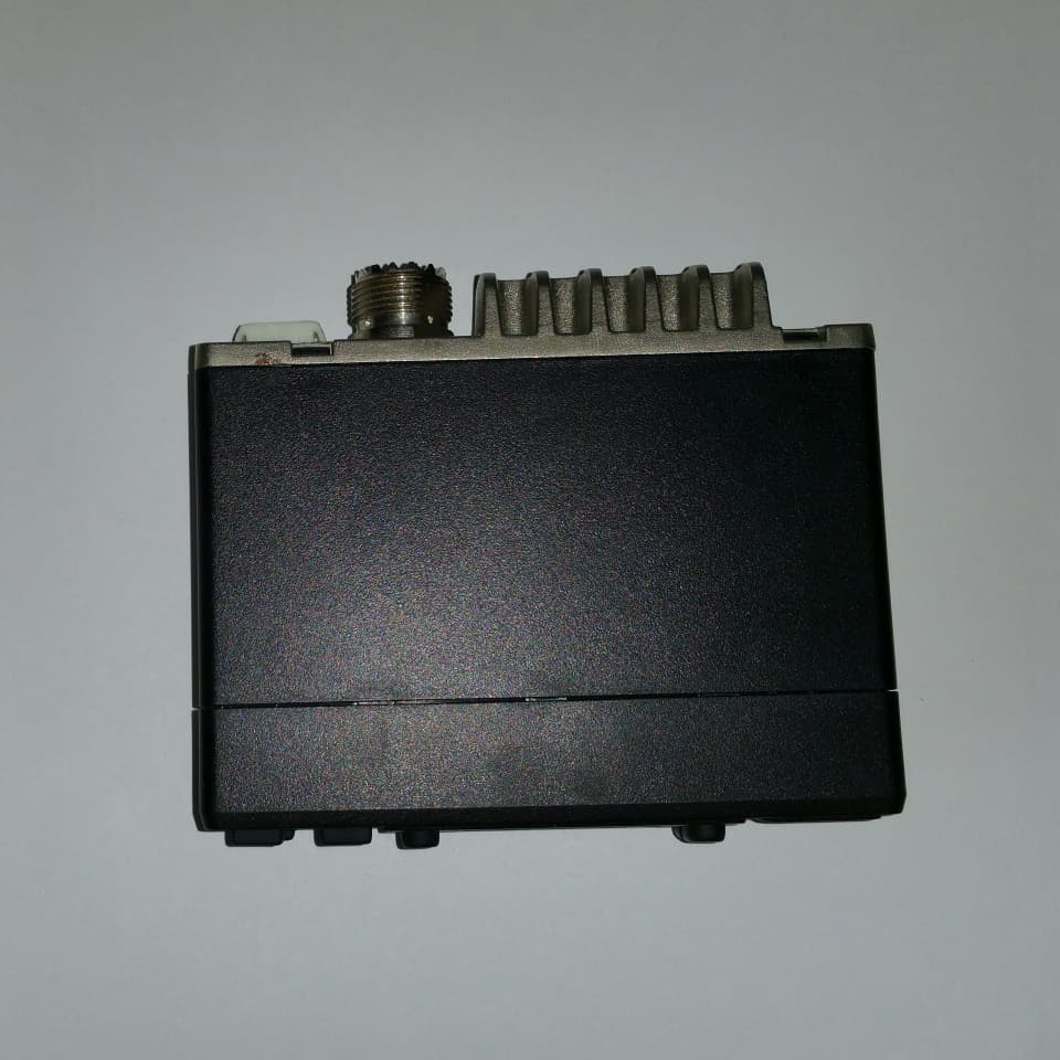
Click to zoom
Application Details
- Equipment Class
- FRB - Part 95 Family Radio Base Transmitter
- Date of Grant
- Dec 28, 2014
- Application Purpose
- Original Equipment
- Date of Application
- Dec 28, 2014
- Equipment Note
- MOBILE GMRS TRANSCEIVER
- Frequency Range
- 462.55000000 - 462.72500000
- Company
- Midland Radio Corporation
- Country
- United States
Documents & Files
Document Text
Text extracted from the exhibit documents filed with the FCC. Open a document above to read the original.
Users Manual
midlandusa.com MXT100 GMRS Radio OWNER’S MANUAL Model MXT100 Series midlandusa.comPage 2 Welcome to the World of Midland electronics Congratulations on your purchase of a high quality MIDLAND product. Your 2-way radio represents state-of-the-art high-tech engineering. Designed for GMRS (General Mobile Radio Service) operation, this compact package is big on performance. It is a quality piece of electronic equipment, skillfully constructed with the finest components. The circuitry is all solid-state and mounted on a rugged printed circuit board. Your two- way radio is designed for reliable and trouble-free performance for years to come. Features - 15 GMRS Channels - 142 Privacy Codes (38 CTCSS / 104 DCS) - Monitor Function - Keypad Lock - Power HI/LO Settings - External Speaker Jack This device complies with Part 15 of the FCC Rules. Operation is subject to the following two conditions: (1) this device does not cause harmful interference, (2) this radio must accept any interference that may cause undesired operation. To maintain compliance with FCC’s RF exposure guidelines, for body-worn operation, this radio has been tested and meets the FCC RF exposure guidelines when used with Midland Radio Corp. accessories supplied or designated for this product. Use of other accessories may not ensure compliance with FCC RF exposure guidelines, (3) the transmitter must not be co-located or operated in conjunction with any other antenna or transmitter, and (4) this equipment complies with the FCC RF radiation exposure limits set forth for an uncontrolled environment. This equipment should be installed and operated with a minimum safe distance of 20cm between the radiator and any part of your body. Model MXT100 Series midlandusa.comPage 3 IMPORTANT NOTICE, FCC LICENSE REQUIRED FOR GMRS OPERATION (Only Applicable for GMRS Radio Use in the United States) The MXT100 Series operates on GMRS (General Mobile Radio Service) frequencies which require an FCC (Federal Communications Commission) license. You must be licensed prior to operating on channels 1 - 7 or 15 - 22, which comprise the GMRS channels of the MXT100 Series. Serious penalties could result from unlicensed use of GMRS channels, in violation of FCC rules, as stipulated in the Communications Act’s Sections 501 and 502 (amended). You will be issued a call sign by the FCC which should be used for station identification when operating the radio on GMRS channels. You should also cooperate by engaging in permissible transmissions only, avoiding channel interference with other GMRS users, and being prudent with the length of your transmission time. To obtain a license or ask questions about the license application, contact the FCC at 1-888-CALL FCC or go to the FCC’s website: http://www.fcc.gov and request form 605. Exposure To Radio Frequency Energy Your Midland radio is designed to comply with the following national and international standards and guidelines regarding exposure of human beings to radio frequency electromagnetic energy: - United States Federal Communications Commission, Code of Federal Regulations: 47 CFR part 2 sub-part J - American National Standards Institute (ANSI)/Institute of Electrical & Electronics Engineers (IEEE) C95. 1-1992 - Institute of Electrical and Electronics Engineers (IEEE) C95. 1-1999 Edition - National Council on Radiation Protection and Measurements (NCRP) of the United States, Report 86, 1986 - International Commission on Non-lonizing Radiation Protection (ICNIRP) 1998 To control your exposure and ensure compliance with the general population or uncontrolled environment exposure limits, transmit no more than 50% of the time. The radio generates measurable RF energy exposure only when transmitting. IMPORTANT: Changes or modifications to this unit not expressly approved by MIDLAND RADIO CORP. could void your right to operate this unit. Your radio is set up to transmit a regulated signal on an assigned frequency. It is against the law to alter or adjust the settings inside the COMMUNICATOR to exceed those limitations. Any adjustment to your radio must be made by qualified technicians. Model MXT100 Series midlandusa.comPage 4 INSTALLATION This transceiver may be installed in any 12-volt negative ground-system car or truck. Most current U.S. and Foreign vehicles use a negative system, but some older models and some newer large trucks may have a positive ground. Check the requirements for your vehicle before you begin installation. Generally, you have a negative-ground system if the minus (-) battery terminal is connected to the motor block. Contact your dealer in the event you are unable to determine your vehicle’s polarity system. Location Your new Midland GMRS mobile is designed to be installed under the dash or vertically on a console of your vehicle. Safety and convenience are the primary considerations in deciding exactly where to locate your radio. Caution: Be sure that the unit is located so that it does not interfere with the driver, supplemental restraint systems (air bags), or impair access to any controls. Connecting cables must be routed and secured in such a manner as not to interfere with the operation of the brake, accelerator or other controls. Interference from either the unit or connecting cables may contribute to the loss of control of the vehicle. Model MXT100 Series midlandusa.comPage 5 Mounting 1. Plug power cable into back of radio marked “13.8V DC.” Be sure to observe polarity markings. 2. Use the mounting bracket as a template for marking the location of screw holes under the dash. Use a nail or other sharp pointed object to mark the hole locations. 3. Drill a 1/8” hole for each screw hole in the mounting bracket. Attach the bracket to the dash with the Phillips head sheet metal screws provided. 4. Attach removable 2-pin plug-in DC cord to polarized DC jack on the rear of the transceiver. 5. Locate and secure the radio into the mounting bracket, allowing working space for later power connection…
Text truncated - open the document above for the full version.
Cover Letter(s)
5900 Parretta Driv e ● KANSAS CITY, MISSOURI ● 64120 TELEPHONE: (816) 241-8500 ● FAX: (816) 241-5713 EMAIL: mail @midlandradio.com WEBSITE: www.midlandradio.com November 17, 2014 F ederal Communications Commission A uthorization and Evaluation Division C onfidentiality Request regarding application for certification of FCC ID: MMAMXT100 P ursuant to Sections 0.457 and 0.459 of the Commission’s Rules, we hereby request c onfidential treatment of information accompanying this application as outlined below: B lock Diagram S chematic Diagram(s) O perational Description T uning Procedure T he above materials contain trade secrets and proprietary information not customarily r eleased to the public. The public disclosure of these materials may be harmful to the a pplicant and provide unjustified benefits to its competitors. T he applicant understands that pursuant to Section 0.457 of the Rules, disclosure of this a pplication and all accompanying documentation will not be made before the date of the Grant f or this application. S incerely, . Midland Radio Corporation 5900 Parretta Drive, Kansas City, MO. 64120 Phone: (816) 241-8500 Fax: (816) 241-5713 W ebsite: wwwl.midlandradio.com E-Mail: [email protected]
External Photos
APPLICANT: MIDLAND RADIO CORP. FCC ID: MMAMXT100 EXTERNAL PHOTOS
ID Label/Location Info
10mm 13mm R:0.5MM
Internal Photos
APPLICANT: MIDLAND RADIO CORP. FCC ID: MMAMXT100 INTERNAL PHOTOS
RF Exposure Info
RF Exposure Evaluation Report APPLICANT MIDLAND RADIO CORPORATION 5900 PARRETTA DRIVE KANSAS CITY MISSOURI 64120 USA FCC ID MMAMXT100 MODEL NUMBER MXT100 PRODUCT DESCRIPTION MOBILE GMRS STANDARD APPLIED CFR 47 Part 2.1091 PREPARED BY S. S. Sanders We, TIMCO ENGINEERING, INC. would like to declare that the device has been evaluated in accordance with 47 CFR Part 2.1091 and meets the requirements. The attached report shall not be reproduced except in full without the written approval of TIMCO ENGINEERING, INC. 849 NW STATE ROAD 45 NEWBERRY, FL 32669 USA PH: 888.472.2424 OR 352.472.5500 FAX: 352.472.2030 EMAIL: [email protected] HTTP://WWW.TIMCOENGR.COM Applicant: MIDLAND RADIO CORPORATION_MMA FCC ID: MMAMXT100 Report: M\ MIDLAND_MMA\2037BUT14\2037BUT14TestReport.docxt Page 2 of 4 GENERAL REMARKS Attestations This equipment has been evaluated in accordance with the standards identified in this report. To the best of my knowledge and belief, these evaluations were performed using the procedures described in this report. I attest that the necessary evaluations were made, under my supervision, at: Timco Engineering Inc. 849 NW State Road 45 Newberry, Fl 32669 Authorized Signatory Name: Sid Sanders Engineering Project Manager Date: 12/15/2014 RF Exposure Requirements General information Device type: MOBILE GMRS Antenna The manufacturer does not specify an antenna, but a typical antenna has a gain of 0 dBi. Configuration Antenna p/n Type Max. Gain (dBi) Fixed mounted Any omni 0 Operating configuration and exposure conditions: The conducted output power is shown in the table below. Typical use qualifies for a maximum duty cycle factor of 100%. Operation: A typical installation consists of an antenna system with a 10 meter coaxial cable of the type RG 213/ U type which has a loss as follows; Nom. Attenuation for RG 213/U: Frequency MHz Attenuation per 100ft. dB 1 .27 10 .55 50 1.3 100 1.9 200 2.7 400 4.1 700 6.5 900 7.6 1000 8.0 4000 21.5 MPE Calculation: The minimum separation distance is calculated as follows: Applicant: MIDLAND RADIO CORPORATION_MMA FCC ID: MMAMXT100 Report: M\ MIDLAND_MMA\2037BUT14\2037BUT14TestReport.docx The limit for general uncontrolled exposure environment is shown in FCC rule Part 1.11310, Table 1. Max Power 5 WequalsMax Power 5000mW Duty Cycle50%equalsDuty Factor0.5numeric Antenna Gain0 dBiequalsGain numeric1 numeric Coax Loss4.1dBGain - Coax Loss0.389045numeric Power Density 0.31 mW/cm 2 Frequency462.725MHzFrequency rangPower denEnter this value MHz mW/cm 2 mW/cm 2 0.3-1.34100100 1.34-30 180/f 2 0.0 30-3000.20.2 300-1,500f/15000.3 1,500-100,00011 f = frequency in MHz Minimum Separation Distance16cm0.16m Minimum Seperation in Inches6.216108Inches Minimum Separation Distance for Mobile or Fixed Devices General Population/Uncontrolled Exposure Insert values in yellow highlighted boxes to determine Minimum Separation Distance Enter power Density from the chart to the rightRule Part 1.1310, Table 1
Test Report
FCC PART 95 GMRS TRANSCEIVER TEST REPORT APPLICANT MIDLAND RADIO CORPORATION 5900 PARRETTA DRIVE KANSAS CITY MISSOURI 64120 USA FCC ID MMAMXT100 PRODUCT DESCRIPTION MOBILE GMRS FCC STANDARD APPLIED 47 CFR § 95 Personal Radio Service Subpart A – General Mobile Radio Service (GMRS) DATE SAMPLE RECEIVED 11/11/2014 DATE TESTED 12/5/2014 - TESTED BY Sid Sanders APPROVED BY Cory Leverett TIMCO REPORT NO. 2037AUT14TestReportRev1.docx TEST RESULTS PASS FAIL THE ATTACHED REPORT SHALL NOT BE REPRODUCED EXCEPT IN FULL WITHOUT THE WRITTEN APPROVAL OF TIMCO ENGINEERING, INC. 849 NW STATE ROAD 45 NEWBERRY, FL 32669 USA PH: 888.472.2424 OR 352.472.5500 FAX: 352.472.2030 EMAIL: [email protected] HTTP://WWW.TIMCOENGR.COM Applicant: MIDLAND RADIO CORPORATION FCC ID: MMAMXT100 Report: M\ MIDLAND_MMA\2037AUT14\2037AUT14TestReportRev1.docx Page 2 of 19 CONTENTS GENERAL REMARKS ............................................................................................... 3 GENERAL INFORMATION......................................................................................... 4 TEST REPORT SUMMARY ......................................................................................... 5 TEST PROCEDURES: .............................................................................................. 6 RF POWER OUTPUT ................................................................................................ 9 MODULATION CHARACTERISTICS .......................................................................... 10 AUDIO FREQUENCY RESPONSE ....................................................................................... 10 AUDIO INPUT VERSUS MODULATION ............................................................................... 11 POST LIMITER FILTER .................................................................................................... 12 EMISSION DESIGNATOR AND FREQUENCIES .......................................................... 13 OCCUPIED BANDWIDTH ....................................................................................... 14 OCCUPIED BANDWIDTH ....................................................................................... 15 GMRS OCCUPIED BANDWIDTH MASK B ............................................................................ 15 SPURIOUS EMISSIONS AT ANTENNA TERMINALS (CONDUCTED) ............................... 16 FIELD STRENGTH OF SPURIOUS EMISSIONS........................................................... 17 FREQUENCY STABILITY ........................................................................................ 18 EMC EQUIPMENT LIST .......................................................................................... 19 Applicant: MIDLAND RADIO CORPORATION FCC ID: MMAMXT100 Report: M\ MIDLAND_MMA\2037AUT14\2037AUT14TestReportRev1.docx Page 3 of 19 GENERAL REMARKS The attached report shall not be reproduced except in full without the written permission of Timco Engineering Inc. The test results relate only to the items tested. Summary The device under test does: fulfill the general approval requirements as identified in this test report not fulfill the general approval requirements as identified in this test report Attestations This equipment has been tested in accordance with the standards identified in this test report. To the best of my knowledge and belief, these tests were performed using the measurement procedures described in this report. All instrumentation and accessories used to test products for compliance to the indicated standards are calibrated regularly in accordance with ISO 17025: 2005 requirements. I attest that the necessary measurements were made, under my supervision, at: Timco Engineering Inc. 849 NW State Road 45 Newberry, Fl 32669 Authorized Signatory Name: Sid Sanders Engineering Project Manager Date: 12/10/14 Table of Contents Applicant: MIDLAND RADIO CORPORATION FCC ID: MMAMXT100 Report: M\ MIDLAND_MMA\2037AUT14\2037AUT14TestReportRev1.docx Page 4 of 19 GENERAL INFORMATION EUT Specification EUT Description MOBILE GMRS EUT Application Short range communications FCC ID MMAMXT100 Operating Frequency GMRS:462.5500-462.7250 MHz Test Frequencies GMRS: 462.5625 MHz No. of Channels 22 Type of Emission 10K5F3E for Channel Spacing of 12.5kHz EUT Power Source 110–120Vac/50–60Hz (Optional AC power Adapter) DC Power 13.8V Battery Operated Exclusively Test Item Prototype Pre-Production Production Type of Equipment Fixed Mobile Portable Test Conditions The temperature was 24-26ºC with a relative humidity of 50-60%. Modification to the EUT None Test Exercise The EUT was placed in continuous transmit mode of operation Applicable Standards ANSI/TIA 603-D:2004, FCC CFR 47 Part 25 Test Facility Timco Engineering Inc. 849 NW State Road 45 Newberry, FL 32669 USA. Table of Contents Applicant: MIDLAND RADIO CORPORATION FCC ID: MMAMXT100 Report: M\ MIDLAND_MMA\2037AUT14\2037AUT14TestReportRev1.docx Page 5 of 19 TEST REPORT SUMMARY Rule Part No. Scope of Work Status Pass/Fail/NA Part 2.1033(c)(6)(7), Part 2.1046(a), PART 95 Subpart A RF Power Output PASS Part 2.1033(a) (b) Modulation Characteristics PASS 2.1049(c), 95.635(b)(1)(3)(7) Emission Mask and Occupied Bandwidths PASS 2.1051 Antenna Conducted Emissions PASS 2.1053, 95.635(b)(7) Field Strength Spurious Emissions PASS Part 2.1055 Part 95.621(b) Frequency Stability PASS Applicant: MIDLAND RADIO CORPORATION FCC ID: MMAMXT100 Report: M\ MIDLAND_MMA\2037AUT14\2037AUT14TestReportRev1.docx Page 6 of 19 TEST PROCEDURES: Power Line Conducted Interference: The procedure used was ANSI/TIA 603-D:2010, using a 50uH LISN. Both lines were observed with the EUT transmitting. The bandwidth of the spectrum analyzer was 10 kHz with an appropriate sweep speed. Bandwidth 20 dB: The measurements were made with the spectrum analyzer's resolution bandwidth (RBW) = 1 MHz and the video bandwidth (VBW) = 3 MHz and the span set as shown on plot. Bandwidth: The measurements were made with the spectrum analyzer…
Text truncated - open the document above for the full version.
Test Setup Photos
APPLICANT: MIDLAND RADIO CORP. FCC ID: MMAMXT100 TEST SET UP PHOTO
Contact Information
Applicant
Butch Rittmann(Director of Operations)
Technical Contact
Timco Engineering, Inc.Sid Sanders
[email protected]888-472-2424
849 NW State Road 45 · Newberry, Florida · United States
Non-Technical Contact
Timco Engineering, Inc.Sharon Hoffman
[email protected]888-472-2424
Test Firm
Timco Engineering, Inc.Bruno Clavier
Technical Specifications
| # | Rule Parts | Frequency Range | Power Output | Emission | Tolerance |
|---|---|---|---|---|---|
| 1 | 95A | 462.55 MHz - 462.725 MHz | 5 W | 10K5F3E | 0.3700000000 ppm |
Other Applications from Midland Radio Corporation

MMAMXMC95
Jun 10, 2026Wireless Bluetooth Microphone
Equipment Class
JAB - Part 15 Class B Digital Device
MMAMXT295
Jun 08, 2026GMRS Radio
Equipment Class
TNF - Licensed Non-Broadcast Transmitter Held to Face
MMACLIPTALK
Apr 27, 2026Transceiver
Equipment Class
DTS - Digital Transmission System
MMABR200S
Jan 13, 2026BUSINESS BAND TWO-WAY RADIO
Equipment Class
TNF - Licensed Non-Broadcast Transmitter Held to Face
MMAGXT67
Oct 29, 2023GMRS RADIO
Equipment Class
TNF - Licensed Non-Broadcast Transmitter Held to Face