MMAMXT575GMRS MOBILE RADIO
Midland Radio Corporation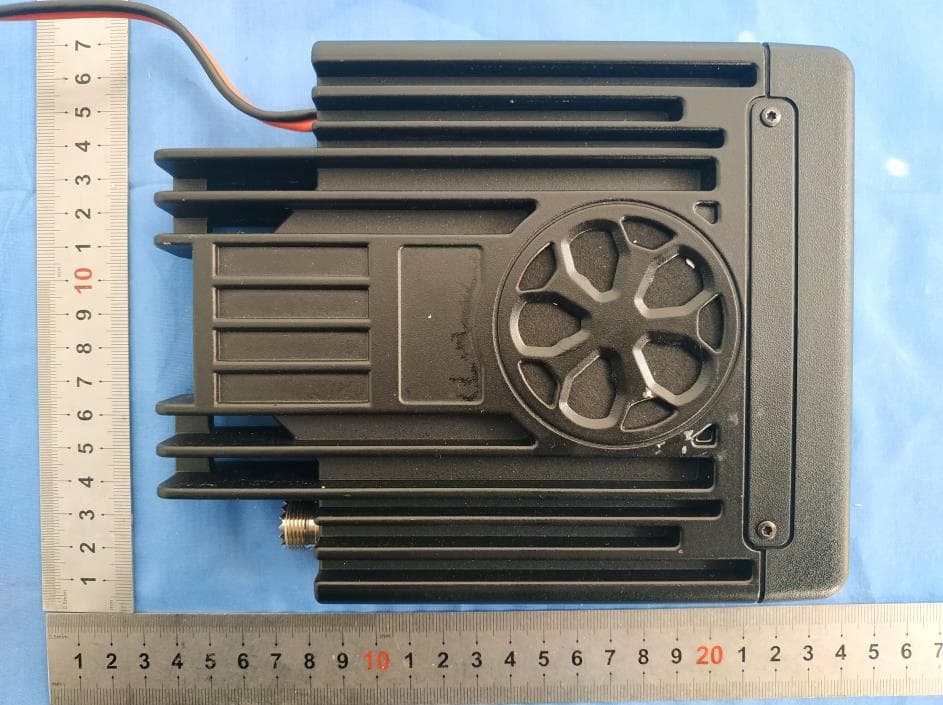
Click to zoom
Application Details
- Equipment Class
- TNB - Licensed Non-Broadcast Station Transmitter
- Date of Grant
- Apr 19, 2021
- Application Purpose
- Original Equipment
- Date of Application
- Apr 19, 2021
- Equipment Note
- GMRS MOBILE RADIO
- Frequency Range
- 467.55000000 - 467.72500000
- Company
- Midland Radio Corporation
- Country
- United States
Documents & Files
Document Text
Text extracted from the exhibit documents filed with the FCC. Open a document above to read the original.
Users Manual
1 TABLE OF CONTENTS WELCOME TO THE WORLD OF MIDLAND RADIO Congratulations on your purchase of a high-quality Midland product. Your MXT575 2-way radio represents state-of-the-art high-tech engineering. Designed for General Mobile Radio Service (GMRS) operation, this compact package is big on performance. It is a quality piece of electronic equipment, skillfully constructed with the finest components. The circuitry is all solid-state and mounted on a rugged printed circuit board. Your MXT575 radio is designed for reliability and trouble-free performance for years to come. FEATURES • • • • • • • • • • • • • • • • • 50-Watt GMR S Radio 15 GMR S Channels 8 Repeater Channels Split Privacy Tones for Repeater Channels 142 Privacy Codes (38 CTCSS/104 DCS) Controls on Mic – ability to remote the unit Monitor Mode Keypad Lock Call Function Scan Function High/Low Power Settings External Speaker Jack Intercom Jack USB-C port – charging only 1 Year Warranty Compatible with all Midland GMRS radios GMRS License Required FCC NOTICE The MXT575 operates on GMRS (General Mobile Radio Service) frequencies, which require a Federal Communications Commission (FCC) license. Serious penalties may result from unlicensed use of GMRS channels, in violation of FCC rules, as stipulated in the Communications Act’s Sections 501 and 502 (amended). You will be issued a call sign by the FCC that should be used for station identification when operating your radio on GMRS channels. You should also cooperate by engaging in permissible transmissions only, avoiding channel interference with other GMRS users, and being prudent with the length of your transmission time. To obtain a license or ask questions about the license application, contact the FCC at 1-888-CALL FCC or go to the FCC’s website: http://www.fcc.gov and request form 605. EXPOSURE TO RADIO FREQUENCY ENGERGY 2 Your Midland radio is designed to comply with the following national and international standards and guidelines regarding exposure of human beings to radio frequency electromagnetic energy: United States Federal Communications Commission, Code of Federal Regulations: 47 CFR part 2 sub-part J American National Standards Institute (ANSI)/Institute of Electrical & Electronics Engineers (IEEE) C95. 1-1992 Institute of Electrical and Electronics Engineers (IEEE) C95. 1-1999 Edition National Council on Radiation Protection and Measurements (NCRP) of the United States, Report 86, 1986 International Commission on Non-lonizing Radiation Protection (ICNIRP) 1998 To control your exposure and ensure compliance with the general population or uncontrolled environment exposure limits, transmit no more than 50% of the time. The radio generates measurable RF energy exposure only when transmitting. The consumer must maintain a minimum safe separation distance of 16 inches (40 cm) from the antenna when transmitting. INSTALLING YOUR RADIO PREPARING FOR INSTALLATION This radio may be installed in any 12-volt negative ground system vehicle. Most current U.S. and foreign vehicles use a negative ground system, but some older models and some newer large trucks may have a positive ground. Check the specifications for your vehicle before beginning installation. Generally, you have a negative-ground system if the negative (-) battery terminal is connected to the motor block. Contact your dealer if you are unable to determine your vehicle’s polarity system. Read these instructions completely before beginning installation. Read and follow all safety precautions in your vehicle’s Service Manual. Make sure all necessary tools, materials, and parts are on hand. Disconnect the negative (-) battery cable before installing your radio. Be sure to reconnect the cable when installation is complete. Determine a mounting location for your radio. The MXT575 is designed to be installed under the dash or vertically on the center console. Choose a location that does not impair visibility or interfere with driving. Also, take into consideration the routing and length of the lead wires and cables to the power source, antenna, and/or optional external speaker. CAUTION: Extreme care should be exercised when drilling into the dash to avoid damage to under dash electronic ignition, cruise control, instrument and/or accessory wiring. INSTALLING THE MOUNTING BRACKET 1. Using the mounting bracket as a template, mark the location of each screw hole. Use a nail or other sharp pointed object to mark the hole locations. 2. Attach the bracket with the supplied self-tapping screws. Tighten the screws securely. DO NOT OVERTIGHTEN. 3. Once the bracket is secured to the vehicle, slide the radio into the bracket. Be sure the radio locks into the bracket so it does not shift while the vehicle is in motion. INSTALLING AN ANTENNA 3 An external antenna (50Ω) is required for the MXT575. The antenna is intended to be attached to the vehicle’s roof, trunk or similar location. Specific installation requirements vary between vehicles. Use the following guidelines to install the antenna: *Where you locate your antenna does make a difference* 1. Metal surfaces covered by fiberglass or vinyl may affect radio range. Avoid these locations. 2. Mount the antenna as high on the vehicle as possible. The higher the better. 3. If possible, mount the antenna in the center of whatever surface you choose. 4. The antenna cable is 19.7 feet (6 meters) long. Be sure the mounting location will allow for connection of the cable to the radio. 5. Be sure the mounting location is clean and dry before installing the antenna. 6. Route the antenna cable through an accessible entry point, such as a rear door or trunk opening. 7. When routing the antenna cable inside the vehicle, keep the cable away from noise sources, such as the ignition system, gauges, etc. 8. Exercise care to prevent cable damage. Make use of existing gaskets, grommets and weather stripping to protect the cable along its route. CONNECTING THE RADIO TO A POWER SOURCE …
Text truncated - open the document above for the full version.
Cover Letter(s)
QA-FR-170-B Company: Midland Radio Corporation Add: 5900 Parretta Drive, Kansas City, Missouri, 64120-2134, United States Tel: 816 241-8500 Fax: 816 241-5713 E-mail: [email protected] FCC Authorization Date: 2020-12-06 FEDERAL COMMUNICATIONS COMMISSION Authorization and Evaluation Division 7435 Oakland Mills Road Columbia, MD 21046 Su bject: Agent Authorization To whom it may concern: We, Midland Radio Corporation, hereby authorizes Bay Area Compliance Laboratories Corporation to act on its behalf in all matters relating to application for Equipment authorization, including the signing of all documents relating to these matters. All acts carried out by Bay Area Compliance Laboratories Corp. on our behalf shall have the same ef fect as our own action. We, the undersigned, hereby certify that we are not subject to a denial of federal benefits, that includes FCC benefits, pursuant to Section 5301 of the Anti-Drug Abuse Act of 1988, 21 U.S.C. 862. This authorization is valid until further written n otice from the applicant. Sincerely, Signature: Typed or Printed Name: Butch Rittmann Title: Director of Operations
Cover Letter(s)
QA-FR-171-A Company: Midland Radio Corporation Add: 5900 Parretta Drive, Kansas City, Missouri, 64120-2134, United States Tel: 816 241-8500 Fax: 816 241-5713 E-mail: [email protected] FCC Confidential Authorization 2020-12-06 FEDERAL COMMUNICATIONS COMMISSIONS Authorization and Evaluation Division 7435 Oakland Mills Road Columbia, MD 21046 Subject: Confidentiality Request regarding application for certification of FCC ID: MMAMXT575 In accordance with Sections 0.457 and 0.459 of the Commission’s Rules, Midland Radio Corporation, hereby requests long-term confidential treatment of information accompanying this application as outlined below: The above materials contain proprietary and confidential information not customarily released to the public. The public disclosure of these materials provides unjustified benefits to its competitors in the market. Sincerely, Signature: Typed or Printed Name: Butch Rittmann Title: Director of Operations •Block Diagram •Schematics •Operation Description •BOM/Tune-up •INTERNAL PHOTOGRAPHS
External Photos
EXHIBIT A - EUT EXTERNAL PHOTOGRAPHS
RF Exposure Info
MAXIMUM PERMISSIBLE EXPOSURE TEST REPORT For Midland Radio Corporation 5900 Parretta Drive, Kansas City, Missouri, 64120-2134, United States Report Type: Original Report Product Type: GMRS MOBILE RADIO Project Engineer: CK Huan g Re port Number: RXM201206050-00B Re port Date: 2021-01-19 Reviewed B y: Oscar Ye EMC Mana ger Prepared By: Bay Area Compliance Laboratories Corp. (Kunshan) No.248 Chenghu Road, Kunshan, Jiangsu province, China Tel: +86-0512-86175000 Fax: +86-0512-88934268 www.baclcorp.com.cn FCC ID: MMAMXT575 Bay Area Compliance Laboratories Corp. (Kunshan) Report No.: RXM201206050-00B Page 2 of 10 TABLE OF CONTENTS GENERAL INFORMATION ....................................................................................................................................... 3 PRODUCT DESCRIPTION FOR EQUIPMENT UNDER TEST (EUT) ..................................................................................... 3 TEST EQUIPMENT LIST ........................................................................................................................................... 4 FCC §2.1091 - MAXIMUM PERMISSIBLE EXPOSURE (MPE) ........................................................................... 5 APPLICABLE STANDARD .............................................................................................................................................. 5 TEST DATA .................................................................................................................................................................. 7 TEST SETUP PHOTO .................................................................................................................................................. 9 Bay Area Compliance Laboratories Corp. (Kunshan) Report No.: RXM201206050-00B Page 3 of 10 GENERAL INFORMATION Product Description for Equipment under Test (EUT) Applicant Midland Radio Corporation Tested Model MXT-575 Product Type GMRS MOBILE RADIO Modulation Mode FM Channel Spacing 25 kHz Maximum Output Power(ERP) 462.5500-462.7250MHz: 46.89dBm 462.5625-462.7125MHz: 36.11dBm 467.5500-467.7250MHz: 46.69dBm Operation Frequency 462.5500-462.7250MHz 462.5625-462.7125MHz 467.5500-467.7250MHz Power Supply DC 13.8V *Antenna Gain 2.1 dBi Note*: The Maximum Antenna Gain was provided by manufacturer. All measurement and test data in this report was gathered from production sample serial number: RXM201206050-1. (Assigned by the BACL. The EUT supplied by the applicant was received on 2020-12-06) Bay Area Compliance Laboratories Corp. (Kunshan) Report No.: RXM201206050-00B Page 4 of 10 TEST EQUIPMENT LIST Manufacturer Description Model Serial Number Calibration Date Calibration Due Date Narda Isotropic probe NARD-EA509101158 2020-11-19 2021-11-18 Narda Broadban d Field Mete r NBM-550 B-1130 2020-11-19 2021-11-18 * Statement of Traceability: Bay Area Compliance Laboratories Corp. (Kunshan) attests that all calibrations have been performed in accordance to requirements that traceable to National Primary Standards and International System of Units (SI). Bay Area Compliance Laboratories Corp. (Kunshan) Report No.: RXM201206050-00B Page 5 of 10 FCC §2.1091 - MAXIMUM PERMISSIBLE EXPOSURE (MPE) Applicable Standard According to §2.1091 and §1.1310, systems operating under the provisions of this section shall be operated in a manner that ensure that the public is not exposed to radio frequency energy level in excess of the Commission’s guideline. Limits for Maximum Permissible Exposure (MPE) (§1.1310, §2.1091) f = frequency in MHz; * = Plane-wave equivalent power density; Test Procedure 1. Place the EUT`s antenna was vertical polarization on the table. 2. The EUT was set to transmit at the frequency at maximum RF power. 3. The Distance between the test probe and the investigated EUT`s antenna equal to the distance be specified as safety distance in the user manual. 4. Power density measurements were taken at different heights of the probe from the ground (0.8 to 3.0 meters) while rotating versus azimuth (from 0° to 360°) the antenna. 5. Adjusted the distance between the test probe and the tested antenna to the real safe distance, Rreal, such that the measured highest power density in the “worst case” position was the same or slightly less than the test limit. 6. The measurement results of final measurements conducted at the chosen azimuth and different heights of the probe above the ground. Bay Area Compliance Laboratories Corp. (Kunshan) Report No.: RXM201206050-00B Page 6 of 10 Block Diagram of Test Setup 1.5 Meter 1 .0 Meter EUT Non-Conductive Table 150cm above Ground Plane DC Source AC Source Antenna Probe Test Distance Bay Area Compliance Laboratories Corp. (Kunshan) Report No.: RXM201206050-00B Page 7 of 10 Test Data Environmental Conditions Temperature: 22.5 °C Relative Humidity: 50 % ATM Pressure: 101.6 kPa The testing was performed by CK Huang on 2021-01-08 Test Result: Compliant. Test Mode: 462.6250MHz (worst case) Measuring Probe Height(cm) Power Density(mW/cm²) 40cm 50cm 60cm 70cm 80cm 80 0.070 0.069 0.069 0.068 0.067 90 0.088 0.088 0.087 0.087 0.086 100 0.091 0.090 0.089 0.086 0.081 110 0.098 0.098 0.097 0.095 0.092 120 0.112 0.111 0.110 0.107 0.106 130 0.124 0.123 0.122 0.121 0.120 140 0.143 0.143 0.142 0.141 0.140 150 0.184 0.183 0.182 0.181 0.177 160 0.188 0.187 0.187 0.186 0.018 170 0.241 0.240 0.239 0.239 0.199 180 0.194 0.194 0.193 0.193 0.191 190 0.186 0.185 0.185 0.184 0.183 200 0.174 0.173 0.172 0.171 0.170 210 0.114 0.112 0.110 0.107 0.106 220 0.094 0.091 0.088 0.085 0.081 230 0.091 0.090 0.089 0.085 0.090 240 0.082 0.081 0.080 0.079 0.077 250 0.053 0.051 0.050 0.048 0.047 260 0.043 0.042 0.039 0.038 0.037 270 0.022 0.020 0.019 0.018 0.016 280 0.017 0.016 0.014 0.013 0.011 290 0.013 0.012 0.011 0.010 0.009 300 0.011 0.010 0.010 0.009 0.008 Bay Area Compliance Laboratories Corp. (Kunshan) Report No.: RXM201206050-00B Page 8 of 10 Test Result Summary: Maximum Power Density (mW/cm 2 ) 0.241 Measu…
Text truncated - open the document above for the full version.
Test Report
FCC PART 95 TEST REPORT For Midland Radio Corporation 5900 Parretta Drive, Kansas City, Missouri, 64120-2134, United States R e p o r t T y p e: Original Report P r o d u c t T y p e : GMRS MOBILE RADIO Project Engineer: CK Huang Report Number: RXM201206050-00A Report Date: 2021-01-19 Reviewed By: Oscar Ye EMC Manager Prepared By: Bay Area Compliance Laboratories Corp. (Kunshan) No.248 Chenghu Road, Kunshan, Jiangsu province, China Tel: +86-0512-86175000 Fax: +86-0512-88934268 www.baclcorp.com.cn FCC ID: MMAMXT575 Bay Area Compliance Laboratories Corp. (Kunshan) Report No.: RXM201206050-00A FCC Part 95 Page 2 of 36 TABLE OF CONTENTS GENERAL INFORMATION ....................................................................................................................................... 3 PRODUCT DESCRIPTION FOR EQUIPMENT UNDER TEST (EUT) ..................................................................................... 3 OBJECTIVE ................................................................................................................................................................... 3 RELATED SUBMITTAL(S)/GRANT(S) ............................................................................................................................. 3 TEST METHODOLOGY .................................................................................................................................................. 3 MEASUREMENT UNCERTAINTY .................................................................................................................................... 4 TEST FACILITY ............................................................................................................................................................. 4 SYSTEM TEST CONFIGURATION .......................................................................................................................... 5 DESCRIPTION OF TEST CONFIGURATION ...................................................................................................................... 5 EQUIPMENT MODIFICATIONS ....................................................................................................................................... 6 SUPPORT EQUIPMENT LIST AND DETAILS .................................................................................................................... 6 EXTERNAL I/O CABLE.................................................................................................................................................. 6 BLOCK DIAGRAM OF TEST SETUP ................................................................................................................................ 6 SUMMARY OF TEST RESULTS ............................................................................................................................... 8 TEST EQUIPMENT LIST ........................................................................................................................................... 9 FCC §2.1046, §95.1767 - RF OUTPUT POWER ...................................................................................................... 10 APPLICABLE STANDARD ............................................................................................................................................ 10 TEST PROCEDURE ...................................................................................................................................................... 10 TEST DATA ................................................................................................................................................................ 10 FCC §2.1047, §95.1775 - MODULATION CHARACTERISTIC ........................................................................... 12 APPLICABLE STANDARD ............................................................................................................................................ 12 TEST PROCEDURE ...................................................................................................................................................... 12 TEST DATA ................................................................................................................................................................ 12 FCC §2.1049, §95.1773, §95.1779 - AUTHOURIZED BANDWIDTH AND EMISSION MASK ........................ 22 APPLICABLE STANDARD ............................................................................................................................................ 22 TEST PROCEDURE ...................................................................................................................................................... 23 TEST DATA ................................................................................................................................................................ 23 FCC §2.1051 & §95.1779 - SPURIOUS EMISSIONS AT ANTENNA TERMINALS .......................................... 27 APPLICABLE STANDARD ............................................................................................................................................ 27 TEST PROCEDURE ...................................................................................................................................................... 27 TEST DATA ................................................................................................................................................................ 27 FCC §2.1053 & §95.1779 - RADIATED SPURIOUS EMISSION .......................................................................... 31 APPLICABLE STANDARD ............................................................................................................................................ 31 TEST PROCEDURE ............................................................................................................................................…
Text truncated - open the document above for the full version.
Contact Information
Applicant
Butch Rittmann(Director of Operations)
Test Firm
Bay Area Compliance Laboratories Corp. (Kunshan)Mr. John Chan
[email protected]+86 0512 86175000
Technical Specifications
| # | Rule Parts | Frequency Range | Power Output | Emission | Tolerance |
|---|---|---|---|---|---|
| 3 | 95E | 467.55 MHz - 467.725 MHz | 46.67 W | 16K0F3E | 2.5 ppm |
Other Applications from Midland Radio Corporation

MMAMXMC95
Jun 10, 2026Wireless Bluetooth Microphone
Equipment Class
JAB - Part 15 Class B Digital Device
MMAMXT295
Jun 08, 2026GMRS Radio
Equipment Class
TNF - Licensed Non-Broadcast Transmitter Held to Face
MMACLIPTALK
Apr 27, 2026Transceiver
Equipment Class
DTS - Digital Transmission System
MMABR200S
Jan 13, 2026BUSINESS BAND TWO-WAY RADIO
Equipment Class
TNF - Licensed Non-Broadcast Transmitter Held to Face
MMAGXT67
Oct 29, 2023GMRS RADIO
Equipment Class
TNF - Licensed Non-Broadcast Transmitter Held to Face