MMANT3VHF MARINE RADIO
Midland Radio Corporation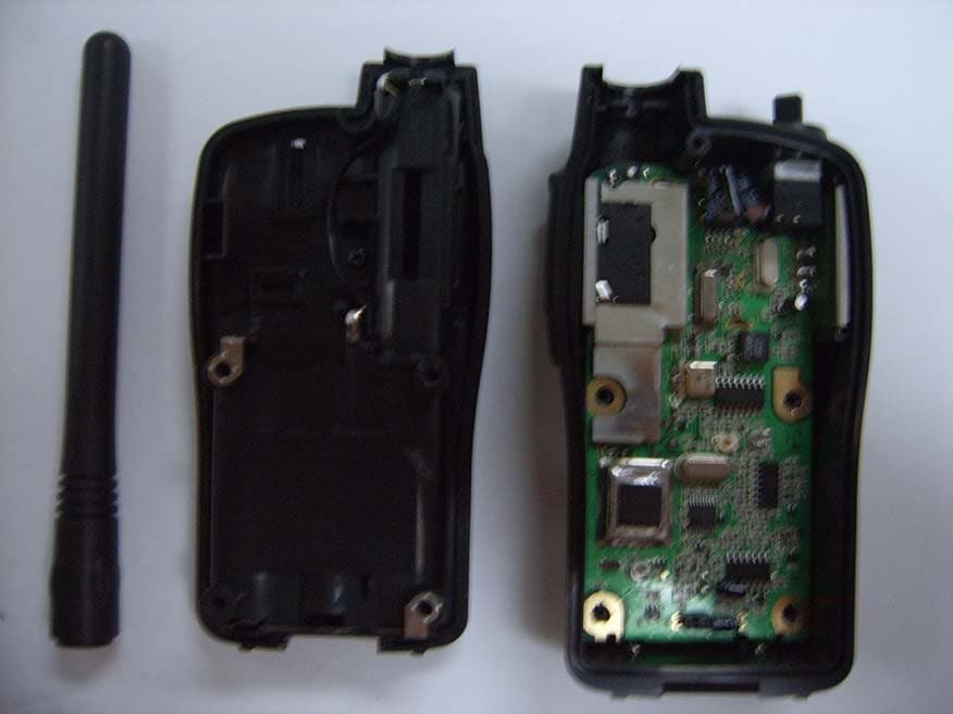
Click to zoom
Application Details
- Equipment Class
- TNF - Licensed Non-Broadcast Transmitter Held to Face
- Date of Grant
- Dec 21, 2006
- Application Purpose
- Original Equipment
- Date of Application
- Dec 20, 2006
- Equipment Note
- VHF MARINE RADIO
- Frequency Range
- 156.02500000 - 157.42500000
- Company
- Midland Radio Corporation
- Country
- United States
Documents & Files
Document Text
Text extracted from the exhibit documents filed with the FCC. Open a document above to read the original.
Users Manual
NAUTICO 3 ® OWNER'S MANUAL TM VHF MARINE RADIO www.midlandradio.com ® Model NT3 Series Page 2www.midlandradio.com TABLE OF CONTENTS2 Introduction3 Important Notice, FCC Licensing4 LCD Display5 Controls5 Battery Installation6 Installing the Belt Clip6 Charging the Optional Battery Pack7 Operating Your Radio7 - 12 External Speaker/Microphone Jack12 Troubleshooting Guide13 Use and Care13 Specifications and Frequency Charts14 -16 Warranty Information17 MIDLAND Family Products18 Accessories18 Accessories Order Form19 ® Page 3www.midlandradio.com Welcome to the world of Midland electronics Congratulations on your purchase of a high quality MIDLAND product. Your 2-way radio represents the state-of-the-art in high-tech engineer- ing. Designed for VHF Marine Service operation, this compact pack- age is big on performance. It is a quality piece of electronic equipment, skillfully constructed with the finest components. The circuitry is all solid-state and mounted on a rugged printed circuit board. Your 2-way radio is designed to give you reliable and trouble-free performance for years to come. Features - Marine Channels: 57 USA / 61 Canada / 57 International (grouped by area) - eVOX - Selectable CALL Tone - NOAA Weather Radio - SCAN Function - MONITOR Function - Roger Beep Tone - Key Pad Lock - Power High / Power Low Settings - Speaker / Microphone Jacks - Battery Indicator Model NT3 Series This device complies with Part 15 of the FCC Rules. Operation is subject to the following two conditions: (1) this device does not cause harmful interference, and (2) this radio must accept any interference that may cause undesired operation. To maintain compliance with FCC's RF exposure guidelines, for body-worn operation, this radio has been tested and meets the FCC RF exposure guidelines when used with Midland Radio Corp. accessories supplied or designated for this product. Use of other accessories may not ensure compliance with FCC RF expo- sure guidelines. The NAUTICO3 operates on VHF Marine Radio Service frequencies, in compli- ance with Federal Communications Commission (FCC) requirements. Recreational boaters are not currently required to have a Ship Radio License. The USCG recommends that the boat's registration number and state be used for the radio call sign. ® Page 4www.midlandradio.com FCC LICENSE A ship station license is not required for any vessel traveling in U.S. waters which is less than 20 meters in length. However, any vessel required to carry an HF SSB radiotelephone or marine satellite terminal is required to have a ship station license. FCC license forms can be downloaded at www.fcc.gov/forms. You may also obtain a form from the FCC by calling (888) 225-5322. Exposure To Radio Frequency Energy Your Midland radio is designed to comply with the following national and international standards and guidelines regarding exposure of human being to radio frequency electromagnetic energy: - United States Federal Communications Commission, Code of Federal Regulations: 47 CFR part 2 sub-part J - American National Standards Institute (ANSI)/Institute of Electrical & Electronic Engineers (IEEE) C95. 1-1992 - Institute of Electrical and Electronic Engineer (IEEE) C95. 1-1999 Edition - National Council on Radiation Protection and Measurements (NCRP) of the United States, Report 86, 1986 - International Commission on Non-lonizing Radiation Protection (ICNIRP) 1998 To control your exposure and ensure compliance with the general population or uncontrolled environment exposure limits, transmit no more than 50% of the time. The radio generates measurable RF energy exposure only when transmitting. Model NT3 Series IMPORTANT:Changes or modifications to this unit not expressly approved by MIDLAND RADIO CORP. could void your right to operate this unit. Your radio is set up to transmit a regulated signal on an assigned frequency. It is against the law to alter or adjust the settings inside the COMMUNICATOR to exceed those limitations. Any adjust- ment to your radio must be made by qualified technicians. ® Page 5www.midlandradio.com Model NT3 Series RX LO INT USA CAN TX VOX CONTROLS RX LO INT USA CAN TX VOX LCD DISPLA Y 1. VOX ICON - Indicates when eVOX mode is active. 2. TRANSMIT (TX) ICON - Indicates adio is transmitting a signal. 3. LOW BATTERY ICON - Indicates battery level is low. 4. CHANNEL NUMBER - Changes from 1~88a on VHF Marine band (1~10 on WX band). 5. USA/CAN/INT CHANNEL ICONS 6. KEY LOCK ICON - Indicates KEY LOCK mode is on. 7. WX BAND ICON - Indicates when the radio is in Weather Band mode 8. TRANSMIT POWER LEVEL (Hi / LO) ICON- Indicates TX Power setting. 9. RECEIVE (RX) ICON - Indicates radio is receiving a transmission. 10. POWER/VOLUME KNOB - Turn clock wise to turn the power on and increase the volume level. Turn counter-clockwise to decrease the volume level and turn the power off. 11. PTT Button - Press and hold to transmit voice communication. Press twice quickly to send a call tone. 12. CH 16 Button - Press to switch immedi- ately to emergency channel 16. Press and hold to switch to Channel 9. 13. MIC - Built-in microphone. 14. SPEAKER - Built-in speaker. 15. ANTENNA. 16. EXTERNAL SPEAKER/MIC JACK. 17. MENU Button - Press to access MENU mode. Press and hold to go to WX Band Receiver mode. 18. MONITOR/SCAN Button - Press to enter SCAN mode. Press and hold to enter MONITOR mode. 19. UP/DOWN Button - Make adjustments in MENU mode. 1 2 3 4 5 6 7 8 9 10 11 12 13 14 19 18 17 16 15 ® Page 6www.midlandradio.com BA TTERY INSTALLATION Your NAUTICO3 radio operates with either 4 AA alkaline batteries or an optional NiMH battery pack. The belt clip should be removed (see below) to ease installation or removal of the batteries. To install the batteries: 1. With the back of the radio facing you, remove the belt clip (see diagram below) for easy access, then remove the Battery Cover by pressing down on the top center and sliding it down from the radio. 2. Insert 4 AA batteries observing the polarity as sho…
Text truncated - open the document above for the full version.
Cover Letter(s)
November 09, 2006 Federal Communications Commission Authorization and Evaluation Division Confidentiality Request regarding application for certification of FCC ID: MMANT3 Pursuant to Sections 0.457 and 0.459 of the Commission’s Rules, we hereby request confidential treatment of information accompanying this application as outlined below: Exhibit Type File Name Schematics Diagram(s) MMANT3-Schematic Confidentiality.PDF Operational Description MMANT3-Operational Description Confidentiality.PDF Block Diagram MMANT3-Block Diagram Confidentiality.PDF The above materials contain trade secrets and proprietary information not customarily released to the public. The public disclosure of these materials may be harmful to the applicant and provide unjustified benefits to its competitors. The applicant understands that pursuant to Section 0.457 of the Rules, disclosure of this application and all accompanying documentation will not be made before the date of the Grant for this application. Sincerely, Midland Radio Corporation 5900 Parretta, Drive, Kansas City, MO 64120 .
Parts List/Tune Up Info
GLOBALLINK CORPORATION LTD. NT3 - Bill of Material (Ver.AAA) Dwg.No : NT3-BOM Rev.Date : 20 Oct.. 2006 Ref.NoItemsDescriptionQ'ty Q3BFQ67WTRANSISTOR CHIP 1 Q4BFQ67WTRANSISTOR CHIP 1 C201PFCHIP CAPACITOR 0402 NPO ±0.25PF1 C223A3PFCHIP CAPACITOR 0402 NPO ±0.25PF1 C223B3PFCHIP CAPACITOR 0402 NPO ±0.25PF1 C1904PFCHIP CAPACITOR 0402 NPO ±0.25PF1 C2185PFCHIP CAPACITOR 0402 NPO ±0.25PF1 C3035PFCHIP CAPACITOR 0402 NPO ±0.25PF1 C3047PFCHIP CAPACITOR 0402 NPO ±0.25PF1 C3128PFCHIP CAPACITOR 0402 NPO ±0.25PF1 C224A8PFCHIP CAPACITOR 0402 NPO ±0.25PF1 C410PFCHIP CAPACITOR 0402 NPO ±5%1 C4510PFCHIP CAPACITOR 0402 NPO ±5%1 C30710PFCHIP CAPACITOR 0402 NPO ±5%1 C5912PFCHIP CAPACITOR 0402 NPO ±5%1 C11512PFCHIP CAPACITOR 0402 NPO ±5%1 C8615PFCHIP CAPACITOR 0402 NPO ±5%1 C17918PFCHIP CAPACITOR 0402 NPO ±5%1 C4122PFCHIP CAPACITOR 0402 NPO ±5%1 C22422PFCHIP CAPACITOR 0402 NPO ±5%1 C31122PFCHIP CAPACITOR 0402 NPO ±5%1 C2127PFCHIP CAPACITOR 0402 NPO ±5%1 C14827PFCHIP CAPACITOR 0402 NPO ±5%1 C22327PFCHIP CAPACITOR 0402 NPO ±5%1 C3733PFCHIP CAPACITOR 0402 NPO ±5%1 C4433PFCHIP CAPACITOR 0402 NPO ±5%1 C20833PFCHIP CAPACITOR 0402 NPO ±5%1 C20933PFCHIP CAPACITOR 0402 NPO ±5%1 C6447PFCHIP CAPACITOR 0402 NPO ±5%1 C30947PFCHIP CAPACITOR 0402 NPO ±5%1 C12868PFCHIP CAPACITOR 0402 NPO ±5%1 C13968PFCHIP CAPACITOR 0402 NPO ±5%1 C22268PFCHIP CAPACITOR 0402 NPO ±5%1 C29220PFCHIP CAPACITOR 0402 NPO ±5%1 C31220PFCHIP CAPACITOR 0402 NPO ±5%1 C306220PFCHIP CAPACITOR 0402 NPO ±5%1 C91330PFCHIP CAPACITOR 0402 NPO ±5%1 C1470PFCHIP CAPACITOR 0402 X7R ±10%1 C7470PFCHIP CAPACITOR 0402 X7R ±10%1 C10470PFCHIP CAPACITOR 0402 X7R ±10%1 C11470PFCHIP CAPACITOR 0402 X7R ±10%1 C14470PFCHIP CAPACITOR 0402 X7R ±10%1 C19470PFCHIP CAPACITOR 0402 X7R ±10%1 C23470PFCHIP CAPACITOR 0402 X7R ±10%1 C25470PFCHIP CAPACITOR 0402 X7R ±10%1 C26470PFCHIP CAPACITOR 0402 X7R ±10%1 C28470PFCHIP CAPACITOR 0402 X7R ±10%1 C35470PFCHIP CAPACITOR 0402 X7R ±10%1 C39470PFCHIP CAPACITOR 0402 X7R ±10%1 C46470PFCHIP CAPACITOR 0402 X7R ±10%1 C49470PFCHIP CAPACITOR 0402 X7R ±10%1 C54470PFCHIP CAPACITOR 0402 X7R ±10%1 C56470PFCHIP CAPACITOR 0402 X7R ±10%1 C61470PFCHIP CAPACITOR 0402 X7R ±10%1 C62470PFCHIP CAPACITOR 0402 X7R ±10%1 C63470PFCHIP CAPACITOR 0402 X7R ±10%1 C66470PFCHIP CAPACITOR 0402 X7R ±10%1 C68470PFCHIP CAPACITOR 0402 X7R ±10%1 C73470PFCHIP CAPACITOR 0402 X7R ±10%1 C74470PFCHIP CAPACITOR 0402 X7R ±10%1 C76470PFCHIP CAPACITOR 0402 X7R ±10%1 C79470PFCHIP CAPACITOR 0402 X7R ±10%1 C81470PFCHIP CAPACITOR 0402 X7R ±10%1 Global Link Corporation Confidential Proprietarypage1/ 7 GLOBALLINK CORPORATION LTD. NT3 - Bill of Material (Ver.AAA) Dwg.No : NT3-BOM Rev.Date : 20 Oct.. 2006 Ref.NoItemsDescriptionQ'ty C85470PFCHIP CAPACITOR 0402 X7R ±10%1 C95470PFCHIP CAPACITOR 0402 X7R ±10%1 C103470PFCHIP CAPACITOR 0402 X7R ±10%1 C104470PFCHIP CAPACITOR 0402 X7R ±10%1 C105470PFCHIP CAPACITOR 0402 X7R ±10%1 C116470PFCHIP CAPACITOR 0402 X7R ±10%1 C118470PFCHIP CAPACITOR 0402 X7R ±10%1 C119470PFCHIP CAPACITOR 0402 X7R ±10%1 C120470PFCHIP CAPACITOR 0402 X7R ±10%1 C121470PFCHIP CAPACITOR 0402 X7R ±10%1 C122470PFCHIP CAPACITOR 0402 X7R ±10%1 C123470PFCHIP CAPACITOR 0402 X7R ±10%1 C126470PFCHIP CAPACITOR 0402 X7R ±10%1 C129470PFCHIP CAPACITOR 0402 X7R ±10%1 C132470PFCHIP CAPACITOR 0402 X7R ±10%1 C136470PFCHIP CAPACITOR 0402 X7R ±10%1 C137470PFCHIP CAPACITOR 0402 X7R ±10%1 C140470PFCHIP CAPACITOR 0402 X7R ±10%1 C141470PFCHIP CAPACITOR 0402 X7R ±10%1 C142470PFCHIP CAPACITOR 0402 X7R ±10%1 C143470PFCHIP CAPACITOR 0402 X7R ±10%1 C144470PFCHIP CAPACITOR 0402 X7R ±10%1 C160470PFCHIP CAPACITOR 0402 X7R ±10%1 C162470PFCHIP CAPACITOR 0402 X7R ±10%1 C165470PFCHIP CAPACITOR 0402 X7R ±10%1 C166470PFCHIP CAPACITOR 0402 X7R ±10%1 C169470PFCHIP CAPACITOR 0402 X7R ±10%1 C170470PFCHIP CAPACITOR 0402 X7R ±10%1 C172470PFCHIP CAPACITOR 0402 X7R ±10%1 C173470PFCHIP CAPACITOR 0402 X7R ±10%1 C174470PFCHIP CAPACITOR 0402 X7R ±10%1 C177470PFCHIP CAPACITOR 0402 X7R ±10%1 C178470PFCHIP CAPACITOR 0402 X7R ±10%1 C180470PFCHIP CAPACITOR 0402 X7R ±10%1 C181470PFCHIP CAPACITOR 0402 X7R ±10%1 C182470PFCHIP CAPACITOR 0402 X7R ±10%1 C183470PFCHIP CAPACITOR 0402 X7R ±10%1 C184470PFCHIP CAPACITOR 0402 X7R ±10%1 C185470PFCHIP CAPACITOR 0402 X7R ±10%1 C186470PFCHIP CAPACITOR 0402 X7R ±10%1 C188470PFCHIP CAPACITOR 0402 X7R ±10%1 C207470PFCHIP CAPACITOR 0402 X7R ±10%1 C213470PFCHIP CAPACITOR 0402 X7R ±10%1 C219470PFCHIP CAPACITOR 0402 X7R ±10%1 C305470PFCHIP CAPACITOR 0402 X7R ±10%1 C308470PFCHIP CAPACITOR 0402 X7R ±10%1 C314470PFCHIP CAPACITOR 0402 X7R ±10%1 C108820PFCHIP CAPACITOR 0402 X7R ±10%1 C80.001UFCHIP CAPACITOR 0402 X7R ±10%1 C150.001UFCHIP CAPACITOR 0402 X7R ±10%1 C220.001UFCHIP CAPACITOR 0402 X7R ±10%1 C420.001UFCHIP CAPACITOR 0402 X7R ±10%1 C670.001UFCHIP CAPACITOR 0402 X7R ±10%1 C800.001UFCHIP CAPACITOR 0402 X7R ±10%1 C820.001UFCHIP CAPACITOR 0402 X7R ±10%1 C830.001UFCHIP CAPACITOR 0402 X7R ±10%1 C1250.001UFCHIP CAPACITOR 0402 X7R ±10%1 C1450.001UFCHIP CAPACITOR 0402 X7R ±10%1 C2210.001UFCHIP CAPACITOR 0402 X7R ±10%1 C1380.0018UFCHIP CAPACITOR 0402 X7R ±10%1 C160.0022UFCHIP CAPACITOR 0402 X7R ±10%1 C320.0022UFCHIP CAPACITOR 0402 X7R ±10%1 C870.0022UFCHIP CAPACITOR 0402 X7R ±10%1 Global Link Corporation Confidential Proprietarypage2/ 7 GLOBALLINK CORPORATION LTD. NT3 - Bill of Material (Ver.AAA) Dwg.No : NT3-BOM Rev.Date : 20 Oct.. 2006 Ref.NoItemsDescriptionQ'ty C920.0022UFCHIP CAPACITOR 0402 X7R ±10%1 C930.0022UFCHIP CAPACITOR 0402 X7R ±10%1 C1090.0022UFCHIP CAPACITOR 0402 X7R ±10%1 C1110.0022UFCHIP CAPACITOR 0402 X7R ±10%1 C580.0047UFCHIP CAPACITOR 0402 X7R ±10%1 C900.0047UFCHIP CAPACITOR 0402 X7R ±10%1 C1000.0047UFCHIP CAPACITOR 0402 X7R ±10%1 C970.0068UFCHIP CAPACITOR 0402 X7R ±10%1 C130.01UFCHIP CAPACITOR 0402 X7R ±10%1 C270.01UFCHIP CAPACITOR 0402 X7R ±10%1 C500.01UFCHIP CAPACITOR 0402 X7R ±10%1 C770.01UFCHIP CAPACITOR 0402 X7R ±10%1 C1670.01UFCHIP CAPACITOR 0402 X7R ±10%1 C1680.01UFCHIP CAPACITOR 0402 X7R ±10%1 C50.022UFCHIP CAPACITOR 0402 X7R ±10%1 C990.022UFCHIP CAPACITOR 0402 X7R ±10%1 C1100.022UFCHIP CAPA…
Text truncated - open the document above for the full version.
Parts List/Tune Up Info
Model No: NT3 Drawing No: NT3-ALIGN-M-00 Customer: Midland Title: NT3 Alignment Procedure Rev. Date: Oct. 23, 2006 Created by: Approved by: Rev. No: 00 For Stage : Release Date : Oct. 23, 2006 Page 1 of 1 These drawings and specifications are the property of Global Link Corporation Ltd. and shall not be reproduced or copied, or used as reference for design, manufacture, and sale of device without permission. NT3 Alignment Procedure Model No: NT3 Drawing No: NT3-ALIGN-M-00 Customer: Midland Title: NT3 Alignment Procedure Rev. Date: Oct. 23, 2006 Created by: Approved by: Rev. No: 00 For Stage : Release Date : Oct. 23, 2006 Page 2 of 2 These drawings and specifications are the property of Global Link Corporation Ltd. and shall not be reproduced or copied, or used as reference for design, manufacture, and sale of device without permission. 1. REFERENCE TEST EQUIPMENT 1) HP8921A Cell site test set or HP8921A,B Communication Test Set with Spectrum Analyzer option. 2) Fluke 187 Digital Voltmeter 3) HP E3615A Power supply 2.TEST POINT 1) Antenna : Test point is not prepared. Use antenna contact with Antenna_GND_T(antenna ground). 2) VCO reference voltage : Test point 1 is prepared. 3) TX Audio output : Test point SPKOUT is prepared or use ear-jack(3.5mm) 4) TX Mic. Input : Test point MICIN is prepared or use ear-jack(2.5mm) with 10uF coupling capacitor. 5) Battery Vcc : Test point is not prepared. Please use mechanical contact. 6) Up Key : Test point UP is prepared. 7) Down Key : Test point DW is prepared. 8) Function/Power Key : Test point POWER is prepared. 9) Monitor Key : Test point SCAN is prepared. 10) PTT Key : Test point PTT is prepared. 11) CALL Key : Test point CALL is prepared. Note: All key can be activated when connect with ground. 3.VCO ALIGNMENT 1) Set unit to Channel 1 and connect a voltmeter to TP1 (VCO PD) 2) Press & hole PTT. 3) Extend L303 until the voltmeter reads 1.0V. 4) Cover shield-plate on VCO can and monitor the voltage an TP1. The voltage should be 1.5Vdc +/- 0.2Vdc. If the voltage is not 1.5Vdc +/- 0.2Vdc, realign L303 until meet to requirement. Model No: NT3 Drawing No: NT3-ALIGN-M-00 Customer: Midland Title: NT3 Alignment Procedure Rev. Date: Oct. 23, 2006 Created by: Approved by: Rev. No: 00 For Stage : Release Date : Oct. 23, 2006 Page 3 of 3 These drawings and specifications are the property of Global Link Corporation Ltd. and shall not be reproduced or copied, or used as reference for design, manufacture, and sale of device without permission. 5) Release PTT button so units is in receiving mode and monitor the voltage on TP1. The voltage should be in the range 1.0Vdc +/- 0.5V. 6) Set unit to channel 88A. 7) Press & hold the PTT switch and observe the voltage on TP4. The voltage should be 2-3.5Vdc. 8) Release PTT and observe the voltage on TP4. The voltage should read between 2.0-3.5Vdc. Note: VCO shield-can should be soldered after VCO alignment is finished. 4.TRANSMITTER FREQUENCY ALIGNMENT 1) Press & hold the PTT button. 2) Align CT201 trimmer capacitor such that the output frequency is equal to the channel frequency with a maximum error of +/- 200Hz. CT201 is located on the near side of 20.95MHz X-tal. 5. TRANSMITTER OUTPUT POWER CONFIRMATION 1) A. Set unit to channel 1 and power Hi mode. 2) Press & hold the PTT button. 3) Transmit power should normally be between 4.5W to 5.5W. 4) Set unit to power low mode. 5) Press & hold the PTT button. Ensure that TX power should be between 0.5-1.5W. 6. TRANSMITTER DEVIATION ALIGNMENT 1) Connect an audio generator (600 ohms) to the ear jack. The audio frequency should be set at 1KHz with a level of 200mV RMS. 2) Connect an FM deviation meter (communications test set ) to Antenna contact. Set the monitor to read peak to peak divided by two [(pk-pk)/2] deviation. Set filter of equipment from 25Hz to 15KHz. 3) Press & hold the PTT button. 4) Align RV2 for +/-4.0KHz deviation (+/-0.1KHz). Model No: NT3 Drawing No: NT3-ALIGN-M-00 Customer: Midland Title: NT3 Alignment Procedure Rev. Date: Oct. 23, 2006 Created by: Approved by: Rev. No: 00 For Stage : Release Date : Oct. 23, 2006 Page 4 of 4 These drawings and specifications are the property of Global Link Corporation Ltd. and shall not be reproduced or copied, or used as reference for design, manufacture, and sale of device without permission. 5) Decrease audio generator level until deviation reads +/-3KHz (approximately 4mV) and record generator level. Level should be between 2 mV and 8mV. 6) Connect that transmit audio distortion is less the 5%. 7. RECEIVER ALIGNMENT 1) Set the output level of the RF signal generator for -47dBm. The generator should be set for 3.0KHz deviation at 1 KHz audio. 2) Set volume position middle. 3) Connect Audio analyzer to SPKOUT. 4) Set equipment filter 25Hz to 15KHz. 5) Align CF2 to get a maximum output level & a minimum distortion and confirm that RX audio distortion is less than 3%. 6) Confirm that RX sensitivity is less than -120dBm (nominally -123dBm) by reducing the output level of the RF signal generator until a 12 dB SINAD reading is achieved. 7) Set SSG output level until 9dB SINAD sensitivity and align RV1 unit the unit is un- squelched. 8) Set signal generator level to -47dBm. 9) With 3.0KHZ deviation at 1KHz modulation, set volume for maximum audio. Audio level should be on over than 1.7 Vrms. 8. BATTERY INDICTOR CONFIRMATION 1) Set unit to receiving mode. Don’t set transmitter mode. 2) Set power supply voltage to 6v. 3) Decrease power supply voltage until low battery icon blinks. 9. POWER OFF CURRENT CONSUMPTION 1) Set power supply voltage to 6v and connect to unit. 2) Confirm current. It must be less than 100uA. Model No: NT3 Drawing No: NT3-LAB-TAP-M-00 Customer: Midland Title: NT3 Laboratory Testing Procedure Rev. Date: Oct. 23, 2006 Created by: Approved by: Rev. No: 00 For Stage : Release Date : Oct. 23, 2006 Page 1 of 1 These drawings and specifications are the property of Global Link Corporation Ltd. and shall not be reproduc…
Text truncated - open the document above for the full version.
Test Report
THRU Lab & Engineering. 477-6, Hager-Ri, Yoju-Up, Yoju-Gun Kyunggi-Do,469-803, Korea T820318835092F820318835169 email [email protected] APPLICANT: Midland Radio Corporation FCCID #: MMANT3 REPORT #:THRU-612002 COVER SHEET Test Report Product Name: VHF MARINE RADIO FCCID: MMANT3 THRU Applicant: Midland Radio Corporation 5900 Paretta Kansas City, MO 64120 Date Receipt:11/13/2006 Date Tested: 12/06/ 2006 THRU Lab & Engineering. 477-6, Hager-Ri, Yoju-Up, Yoju-Gun Kyunggi-Do,469-803, Korea T820318835092F820318835169 email [email protected] APPLICANT: Midland Radio Corporation FCCID #: MMANT3 1 of 22 REPORT #:THRU-612002 APPLICANT: Midland Radio Corporation FCCID: MMANT3 TEST REPORT: PAGE 2-3...........LIST OF TEST EQUIPMENT PAGE 4-5........... GENERAL INFORMATION &TECHNICAL DESCRIPTION RF POWER OUTPUT PAGE 6..............METHOD OF MEASURING CONDUCTED SPURIOUS EMISSIONS PAGE 7..............TECHNICAL DATA PAGE 8..............AUDIO FREQUENCY RESPONSE PAGE 9............. AUDIO LOW PASS FILTER PAGE 10-11...... MODULATION LIMITING PAGE 12-16.......OCCUPIED BANDWIDTH PAGE 17-18.......FIELD STRENGTH OF SPURIOUS EMISSIONS PAGE 19............METHOD OF MEASURING RADIATED SPURIOUS EMISSIONS PAGE 20............FREQUENCY STABILITY EXHIBITS INCLUDING: BLOCK DIAGRAM SCHEMATIC PARTS LIST USERS MANUAL LABEL SAMPLE LABEL LOCATION EXTERNAL PHOTOGRAPHS INTERNAL PHOTOGRAPHS OPERATIONAL DESCRIPTION TUNING PROCEDURE TEST SET UP PHOTOGRAPHS THRU Lab & Engineering. 477-6, Hager-Ri, Yoju-Up, Yoju-Gun Kyunggi-Do,469-803, Korea T820318835092F820318835169 email [email protected] APPLICANT: Midland Radio Corporation FCCID #: MMANT3 2 of 22 REPORT #:THRU-612002 TEST Equipment List sxd No Description Manufacturer Model No. Serial No. Due Cal. 1 Test Receiver Rohde & Schwarz ESVS10 830489/001 2007.04.23 2 Test Receiver Rohde & Schwarz ESHS 10 825832/014 2007.08.25 3 Test Receiver Rohde & Schwarz ESVS 10 826008/014 2006.05.24 4 Spectrum Analyzer Hewlett Packard 8566B 2311A02394 2007.06.17 5 Spectrum Display Hewlett Packard 85662A 2542A12429 2007.06.17 6 Quasi-peak Adapter Hewlett Packard 85650A 2521A00887 2007.06.17 7 RF Preselector Hewlett Packard 85685A 2648A00504 2007.06.17 8 Preamplifer Hewlett Packard 8449B 3008A00375 2007.04.23 9 Preamplifer Hewlett Packard 8447F 3113A05367 2007.05.09 10 Preamplifer Hewlett Packard 8447F 2805A02570 2005.12.12 11 Preamplifer A.H. Systems PAM-0118 164 2007.04.01 12 Biconical Antenna Eaton Corp. 94455-1 0977 2007.04.01 13 Biconical Antenna EMCO 3104C 9111-2468 2006.06.07 14 Log Periodic Antenna EMCO 3146 2051 2007.05.11 15 Log Periodic Antenna EMCO 3146 8901-2320 2006.03.28 16 Horn Antenna A.H. Systems SAS-571 414 2007.03.17 17 Horn Antenna A.H. Systems SAS-571 781 2006.01.07 18 Loop Antenna Rohde & Schwarz HFH2-Z2.335.4711.52 826532/006 2007.01.31 19 Dipole Antenna Rohde & Schwarz VHAP 574 2007.12.12 20 Dipole Antenna Rohde & Schwarz VHAP 575 2007.12.12 21 Dipole Antenna Rohde & Schwarz UHAP 546 2007.12.12 22 Dipole Antenna Rohde & Schwarz UHAP 547 2007.12.12 23 Signal Generator Rohde & Schwarz SMS 872165/100 2006.04.23 24 Signal Generator Rohde & Schwarz SMX 825459/030 2007.06.15 25 Spectrum Monitor Rohde & Schwarz EZM 862304/007 None 26 Panorama Monitor Rohde & Schwarz EPN 883707/207 None 27 Spectrum Analyzer Advantest Corp. R3261C 61720208 2007.06.05 28 Spcetrum Analyzer Hewlett Packard 8591A 3205A02641 2007.12.12 29 LISN EMCO 3825/2 9111-1912 2007.12.12 30 LISN Solar 8012-50-R-24 8379121 2007.04.25 31 LISN Kyoritsu KNW-242 8-923-2 2007.05.28 32 Plotter Hewlett Packard 7475A 2210A02802 None THRU Lab & Engineering. 477-6, Hager-Ri, Yoju-Up, Yoju-Gun Kyunggi-Do,469-803, Korea T820318835092F820318835169 email [email protected] APPLICANT: Midland Radio Corporation FCCID #: MMANT3 3 of 22 REPORT #:THRU-612002 33 Modulation Analyzer Hewlett Packard 8901B 3438A05094 2007.05.19 34 Waveform Generator Hewlett Packard 33120A US34001190 2007.05.23 35 Audio analyzer Hewlett Packard 8903B 3011A12915 2007.05.23 36 Universal counter Hewlett Packard 5343A 3020A02978 2007.05.23 37 Frequency Counter Tektronic CMC251 TW52489 2007.04.23 38 Temperature & Humidity Chamber TABAI EZPEC CORP.MC711P 112000492 2006.08.27 39 Antenna Mast EMCO 1070-3 9109-1617 None 40 Turn Table EMCO 1080-1,2 9203-1762 None 41 Positioning Controller EMCO 1090 9111-1054 42 Antenna Power Supply Rohde & Schwarz HZ-9 920127 None 43 Pulse Limiter Rohde & Schwarz ESH3-Z2 881052 None 44 Coaxial Take-up Reel EMCO 100817 9109-1684 None THRU Lab & Engineering. 477-6, Hager-Ri, Yoju-Up, Yoju-Gun Kyunggi-Do,469-803, Korea T820318835092F820318835169 email [email protected] APPLICANT: Midland Radio Corporation FCCID #: MMANT3 4 of 22 REPORT #:THRU-612002 GENERAL_INFORMATION 2.1033(c) MIDLAND RADIO CORPORATION will sell the FCC ID: MMANT3 VHF Marine transmitter in quantity, for use under FCC RULES PART 80. 2.1033(c) TECHNICAL_DESCRIPTION (4) Type of Emission: 14K8G3E/14K8F3E Bn = 2M + 2DK M = 3000 D = 4.6KHz (Peak Deviation) K = 1 Bn = 2(3.0K) + 2(4.6K)(1) = 14.8K 80.205 (a) ALLOWED AUTHORIZED BANDWIDTH = 20.00KHz. 2.1033(c)(6) Frequency Range: 156.025 – 157.425 MHz 2.1033(c)(7) Power Range and Controls: There is a user Power switch for High/Low Power. Maximum Output Power Rating: High 4.3 Watts, Low 0.68 Watt (16 CH), High 4.3 Watts, Low 0.68 Watt(88A CH) into a 50 ohm resistive load. 2.1033(c)(8) DC Voltages and Current into Final Amplifier: POWER INPUT FINAL AMPLIFIER ONLY High Low Vce = 6 VDC Vce = 6 VDC Ice = 0.55 A Ice = 0.44 A Pin = 3.30 Watts Pin = 2.64 Watts Function of each electron tube or semiconductor device or other active circuit device is included in the parts list exhibit. 2.1033(c)(9) Complete Circuit Diagrams: The circuit diagrams and block diagrams are included. 2.1033(c)(10) Instruction book. The instruction manual is included. 2.1033(c)(11) Tune-up procedure. The tune-up procedure is included. 2.1033(c)(9) Complete Circuit Diagrams: The circuit diagrams and block diagrams are included. 2.1033(c)(10) Instruction book…
Text truncated - open the document above for the full version.
Test Report
THRU Lab & Engineering. 477-6, Hager-Ri, Yoju-Up, Yoju-Gun Kyunggi-Do,469-803, Korea T820318835092F820318835169 email [email protected] APPLICANT: Midland Radio Corporation FCCID #: MMANT3 4 of 23 REPORT #:THRU-612002 GENERAL_INFORMATION 2.1033(c) MIDLAND RADIO CORPORATION will sell the FCC ID: MMANT3 VHF Marine transmitter in quantity, for use under FCC RULES PART 80. 2.1033(c) TECHNICAL_DESCRIPTION (4) Type of Emission: 14K8G3E/14K8F3E Bn = 2M + 2DK M = 3000 D = 4.6KHz (Peak Deviation) K = 1 Bn = 2(3.0K) + 2(4.6K)(1) = 14.8K 80.205 (a) ALLOWED AUTHORIZED BANDWIDTH = 20.00KHz. 2.1033(c)(6) Frequency Range: 156.025 – 157.425 MHz 2.1033(c)(7) Power Range and Controls: There is a user Power switch for High/Low Power. Maximum Output Power Rating: High 4.3 Watts, Low 0.68 Watt (16 CH), High 4.3 Watts, Low 0.68 Watt(88A CH) into a 50 ohm resistive load. 2.1033(c)(8) DC Voltages and Current into Final Amplifier: POWER INPUT FINAL AMPLIFIER ONLY High Low Vce = 6 VDC Vce = 6 VDC Ice = 0.905A Ice = 0.35A 4 Pin =5.43Watts Pin =2.1 Watts Function of each electron tube or semiconductor device or other active circuit device is included in the parts list exhibit. 2.1033(c)(9) Complete Circuit Diagrams: The circuit diagrams and block diagrams are included. 2.1033(c)(10) Instruction book. The instruction manual is included. 2.1033(c)(11) Tune-up procedure. The tune-up procedure is included. 2.1033(c)(9) Complete Circuit Diagrams: The circuit diagrams and block diagrams are included. 2.1033(c)(10) Instruction book. The instruction manual is included.
Test Setup Photos
THRU Lab & Engineering. 477-6, Hager-Ri, Yoju-Up, Yoju-Gun Kyunggi-Do,469-803, Korea T820318835092F820318835169 email [email protected] APPLICANT: Midland Radio Corporation FCCID #: MMANT3 21 of 23 REPORT #:THRU-612002 THRU Lab & Engineering. 477-6, Hager-Ri, Yoju-Up, Yoju-Gun Kyunggi-Do,469-803, Korea T820318835092F820318835169 email [email protected] APPLICANT: Midland Radio Corporation FCCID #: MMANT3 22 of 23 REPORT #:THRU-612002
Contact Information
Applicant
Butch Rittmann(Director of Operations)
Test Firm
KES Co., Ltd.In-sung Ryu
Technical Specifications
| # | Rule Parts | Frequency Range | Power Output | Emission | Tolerance |
|---|---|---|---|---|---|
| 2 | 8 | 156.025 MHz - 157.425 MHz | 680.00 mW | 14K8F3E | 10 ppm |
Other Applications from Midland Radio Corporation

MMAMXMC95
Jun 10, 2026Wireless Bluetooth Microphone
Equipment Class
JAB - Part 15 Class B Digital Device
MMAMXT295
Jun 08, 2026GMRS Radio
Equipment Class
TNF - Licensed Non-Broadcast Transmitter Held to Face
MMACLIPTALK
Apr 27, 2026Transceiver
Equipment Class
DTS - Digital Transmission System
MMABR200S
Jan 13, 2026BUSINESS BAND TWO-WAY RADIO
Equipment Class
TNF - Licensed Non-Broadcast Transmitter Held to Face
MMAGXT67
Oct 29, 2023GMRS RADIO
Equipment Class
TNF - Licensed Non-Broadcast Transmitter Held to Face