MMAPL150VHF RADIO
Midland Radio Corporation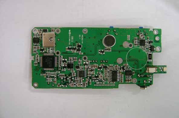
Click to zoom
Application Details
- Equipment Class
- TNF - Licensed Non-Broadcast Transmitter Held to Face
- Date of Grant
- Jul 25, 2006
- Application Purpose
- Original Equipment
- Date of Application
- Jul 25, 2006
- Equipment Note
- VHF RADIO
- Frequency Range
- 148.00000000 - 174.00000000
- Company
- Midland Radio Corporation
- Country
- United States
Documents & Files
Document Text
Text extracted from the exhibit documents filed with the FCC. Open a document above to read the original.
Users Manual
ProLine Series PL2215P / PL2245P User’s Guide Midland Radio Corporation 5900 Parretta Drive Kansas City, Missouri 64120 www.midlandradio.com Printed in KoreaImpreso en Corea P/N: 680-090-2024, Rev. E Notes / Notas: Table of ContentsI. FCC RF Exposure Compliance Requirements - for Occupational Use Only.................................... 1 II. About Midland............................................................. 3 III. About Your Midland ProLine SeriesRadios................ 4 IV. Unpacking and Checking Equipment.......................... 5 V. Radio Control Buttons / Operation Features................ 6 VI. Getting Started............................................................ 7 Charging the NiMH Battery Pack...........................7Attaching and Removing the Battery Pack............. 9Installing the Antenna.............................................10 Installing the Belt Clip.............................................10Installing the Speaker Mic. Jack Cover..................10Attaching the Optional Speaker Mic........................11 VII. Radio Operation..........................................................12 Power On / Transmit.............................................12 VIII. Radio Functions..........................................................13 CTCSS Tone Signaling.........................................13Scan Modes..........................................................13 Normal Channel Scan.........................................13 Priority Channel Scan.........................................14Nuisance Delete....................................................14Busy Channel Lockout..........................................15Marked Idle...........................................................15TX Delay ...............................................................15 Time-Out-Timer (T-O-T)........................................15 Time-Out-Timer Penalty (TX Inhibit)......................15Battery Save.........................................................16Low Battery Warning.............................................16Two-Tone Decode................................................17 i Notes / Notas: Table of Contents, continuedIX. Compatible PL2215P / PL2245P Accessories................... 17 X. Licensing, Safety and Service Information.........................18 FCC Licensing............................................................18Safety Information........................................................18Service........................................................................19 XI. Maintenance......................................................................19 XII. Software Copyrights..........................................................20 XIII. Warranty Statement ..........................................................21 ii XIII. Declaración de Garantía, continuadoLa sola obligación de Midland bajo la presente es reemplazar o reparar elproducto cubierto en esta Garantía. El reemplazo, a opción de Midland,puede incluir un producto similar o que contenga más características. Lareparación puede incluir el reemplazo de piezas o circuitos impresos conpiezas o circuitos impresos funcionalmente equivalentes, reacondicionadoso nuevos. Las piezas, accesorios, pilas o circuitos impresos, reemplazados,están garantizados por el resto de período original. Todas las piezas,accesorios, pilas o circuitos impresos reemplazados se convierten enpropiedad de Midland.LAS GARANTIAS EXPRESAS CONTENIDAS EN LA PRESENTESON A CAMBIO DE TODA OTRA GARANTIA, YA SEA EXPRESA OIMPLICITA O ESTATUTORIA, INCLUYENDO, SIN LIMITACIONES,CUALQUIER GARANTIA DE COMERCIALIZACION O APTITUDPARA UN FIN PARTICULAR.PARA CUALQUIER PRODUCTO QUE NO CUMPLA CON LAGARANTIA ESPECIFICADA, EL UNICO REMEDIO ES LAREPARACIÓN O EL REEMPLAZO. BAJO NINGUNACIRCUNSTANCIA MIDLAND ES RESPONSABLE AL COMPRADORO SUS CLIENTES POR DAÑOS, INCLUYENDO PERJUICIOSESPECIALES, INCIDENTALES, INDIRECTOS O CONSECUENTES,O LA PERDIDA DE GANANCIAS, INGRESOS O DATOSORIGINADOS POR EL USO O LA INCAPACIDAD DE USAR ELPRODUCTO.Esta garantía es nula para ventas y entregas fuera de EE.UU. o Canadá. 45 iii ContenidoI. Requerimientos de Obediencia a la Exposición de RF del FCC - para usoOcupacional Solamente ...... .................................... 23 II. Acerca de Midland......................................................... 25 III. Acerca de Midland ProLine Radios................................. 26 IV. Desempaque y Verificación del Equipo........................... 27 V. Botones de Control del Radio / Rasgos de Funcionamiento......................................................... 28 VI. Preparación.................................................................... 29 Cargador de la Batería de NiMH.............................. 29Instalación y Retiro de la Batería............................... 31Instalación de la Antena............................................. 32 Instalación del Clip de Cinturón................................. 32Instalación de la Cubierta de la Clavija de Conexión de Micrófono de Altavoz.......................... 33Agregando el Micrófono de Altavoz Opcional............ 33 VII. Operación del Radio.................................. ..................... 33 Encienda / Transmite................................................ 33 VIII. Funciones del Radio....................................................... 35 Señalización de Tono CTCSS.................................. 35 Modos de Busq úeda................................................. 35 Busqueda Normal de Canales................................ 35 Busqueda de Canal Prioritario................................ 36Supresión de un Canal............................................. 37Bloqueo de Canal Ocupado...................................... 37Reposo Marcado...................................................... 37Espera TX (Transmisión).......................................... 37Expiracion de Tiempo del Temporizador (T-O-T)...…
Text truncated - open the document above for the full version.
Users Manual
ProLine Series PL2215P / PL2245P User’s Guide Midland Radio Corporation 5900 Parretta Drive Kansas City, Missouri 64120 www.midlandradio.com Printed in KoreaImpreso en Corea P/N: 680-090-2024, Rev. E Notes / Notas: Table of ContentsI. FCC RF Exposure Compliance Requirements - for Occupational Use Only.................................... 1 II. About Midland............................................................. 3 III. About Your Midland ProLine SeriesRadios................ 4 IV. Unpacking and Checking Equipment.......................... 5 V. Radio Control Buttons / Operation Features................ 6 VI. Getting Started............................................................ 7 Charging the NiMH Battery Pack...........................7Attaching and Removing the Battery Pack............. 9Installing the Antenna.............................................10 Installing the Belt Clip.............................................10Installing the Speaker Mic. Jack Cover..................10Attaching the Optional Speaker Mic........................11 VII. Radio Operation..........................................................12 Power On / Transmit.............................................12 VIII. Radio Functions..........................................................13 CTCSS Tone Signaling.........................................13Scan Modes..........................................................13 Normal Channel Scan.........................................13 Priority Channel Scan.........................................14Nuisance Delete....................................................14Busy Channel Lockout..........................................15Marked Idle...........................................................15TX Delay ...............................................................15 Time-Out-Timer (T-O-T)........................................15 Time-Out-Timer Penalty (TX Inhibit)......................15Battery Save.........................................................16Low Battery Warning.............................................16Two-Tone Decode................................................17 i Notes / Notas: Table of Contents, continuedIX. Compatible PL2215P / PL2245P Accessories................... 17 X. Licensing, Safety and Service Information.........................18 FCC Licensing............................................................18Safety Information........................................................18Service........................................................................19 XI. Maintenance......................................................................19 XII. Software Copyrights..........................................................20 XIII. Warranty Statement ..........................................................21 ii XIII. Declaración de Garantía, continuadoLa sola obligación de Midland bajo la presente es reemplazar o reparar elproducto cubierto en esta Garantía. El reemplazo, a opción de Midland,puede incluir un producto similar o que contenga más características. Lareparación puede incluir el reemplazo de piezas o circuitos impresos conpiezas o circuitos impresos funcionalmente equivalentes, reacondicionadoso nuevos. Las piezas, accesorios, pilas o circuitos impresos, reemplazados,están garantizados por el resto de período original. Todas las piezas,accesorios, pilas o circuitos impresos reemplazados se convierten enpropiedad de Midland.LAS GARANTIAS EXPRESAS CONTENIDAS EN LA PRESENTESON A CAMBIO DE TODA OTRA GARANTIA, YA SEA EXPRESA OIMPLICITA O ESTATUTORIA, INCLUYENDO, SIN LIMITACIONES,CUALQUIER GARANTIA DE COMERCIALIZACION O APTITUDPARA UN FIN PARTICULAR.PARA CUALQUIER PRODUCTO QUE NO CUMPLA CON LAGARANTIA ESPECIFICADA, EL UNICO REMEDIO ES LAREPARACIÓN O EL REEMPLAZO. BAJO NINGUNACIRCUNSTANCIA MIDLAND ES RESPONSABLE AL COMPRADORO SUS CLIENTES POR DAÑOS, INCLUYENDO PERJUICIOSESPECIALES, INCIDENTALES, INDIRECTOS O CONSECUENTES,O LA PERDIDA DE GANANCIAS, INGRESOS O DATOSORIGINADOS POR EL USO O LA INCAPACIDAD DE USAR ELPRODUCTO.Esta garantía es nula para ventas y entregas fuera de EE.UU. o Canadá. 45 iii ContenidoI. Requerimientos de Obediencia a la Exposición de RF del FCC - para usoOcupacional Solamente ...... .................................... 23 II. Acerca de Midland......................................................... 25 III. Acerca de Midland ProLine Radios................................. 26 IV. Desempaque y Verificación del Equipo........................... 27 V. Botones de Control del Radio / Rasgos de Funcionamiento......................................................... 28 VI. Preparación.................................................................... 29 Cargador de la Batería de NiMH.............................. 29Instalación y Retiro de la Batería............................... 31Instalación de la Antena............................................. 32 Instalación del Clip de Cinturón................................. 32Instalación de la Cubierta de la Clavija de Conexión de Micrófono de Altavoz.......................... 33Agregando el Micrófono de Altavoz Opcional............ 33 VII. Operación del Radio.................................. ..................... 33 Encienda / Transmite................................................ 33 VIII. Funciones del Radio....................................................... 35 Señalización de Tono CTCSS.................................. 35 Modos de Busq úeda................................................. 35 Busqueda Normal de Canales................................ 35 Busqueda de Canal Prioritario................................ 36Supresión de un Canal............................................. 37Bloqueo de Canal Ocupado...................................... 37Reposo Marcado...................................................... 37Espera TX (Transmisión).......................................... 37Expiracion de Tiempo del Temporizador (T-O-T)...…
Text truncated - open the document above for the full version.
External Photos
PICTURE ( PL 2215P ) FRONT BOTTOM BOTTOM ( WITH BELT CLIP ) UPPER RIGHT SIDE RIGHT SIDE(WITH BELT CLIP) LEFT SIDE LEFT SIDE(WITH BELT CLIP)
External Photos
PICTURE ( PL 2415 ) FRONT BOTTOM BOTTOM ( WITH BELT CLIP ) UPPER RIGHT SIDE RIGHT SIDE(WITH BELT CLIP) LEFT SIDE LEFT SIDE(WITH BELT CLIP)
ID Label/Location Info
DEVICE MUST BE RESTRICTED TO OCCUPATIONAL USE TO SATISFY FCC RF EXPOSURE COMPLIANCE. SEE OWNER’S MANUAL FOR SPECIFIC OPERATING INSTRUCTIONS. CAUTION Label artwork for PL-1145 & PL-2245 Series Portable “FCC Caution Label” prints white letters on black adhesive stock. Typefont is Universe Condensed, 8 pt. Trim marks do not print. Final cut label is 31 mm wide x 13 mm tall ! ! ! ! ! ! ! ! ! !
Internal Photos
PICTURE ( PL 2215P ) FRONT BOTTOM
Internal Photos
PICTURE ( PL 2415 ) FRONT BOTTOM
Operational Description
Theory of Operation 1. Overview PL2415,2215 is VHF handheld transceivers that consist of a receiver, a transmitter, a phase-locked loop(PLL) frequency synthesizer, control circuits and power supply circuits. 2. Receiver system The receiver is double conversion super heterodyne with 1 st IF 45.1MHz and 2 nd IF 455kHz 2-1 Front-end Front-end consists of pre-selector filter, RF Amplifier, Post-selector filter. The receive signal from antenna is applied to band pass filter C72,L6,C143,C43,C51,L18,C144 and routed to an RF amplifier (Q1) after passing transmit/receive switch(D5,6). The signal from pre-selector is amplified around 13dB at RF amp(Q1) and filtered again by Post-selector before applying to Mixer. The signal from Front-end is inputted to Q2 base to be heterodyned with 1 st local signal generated from VCO to be 1 st IF frequency (45.1MHz). The 1 st IF frequency is resonated at tank circuit C61,L14and inputted to Pair crystal filter. 2-3 IF Amplifier The 1 st IF signal is amplified about 15dB by IF amp Q3 and inputted to IF IC(IC1) to be mixed with 2 nd local frequency (44.645MHz). 1 st IF frequency(45.1MHz) and 2 nd local frequency(44.645MHz) are mixed in IC1 which makes 2 nd IF frequency(455KHz) The 2 nd IF frequency passes through ceramic filter to eliminate undesired signal and demodulated by demodulator in IC1 300Hz High Pass Filter U2 removes all signals under 300Hz to keep any undesired signal from being heard from speaker. After passing through this filter, audio signal is de-emphasized by R55,C91 to get 6db/oct response. The de-emphasized audio signal passes through volume control and is amplified to a sufficient level to drive a loud speaker by IC5 Audio AMP. 2-5 Squelch IC1 has a filter that passes noise and an internal amplifier that amplifies the noise and make it as DC voltage to control mute system. So if the noise level is under a threshold, the microprocessor in the radio detects the DC level and un-mutes the radio. If the noise level is over a threshold, the microprocessor mutes the radio. 2-6 Audio AMP After CTCSS,DCS signal is removed at 300Hz High Pass Filter and de-emphasized to – 6 dB/Oct at R55 and C91, the volume of audio signals is controlled by sw/vol1. IC5 amplifies audio signals from sw/vol1 to a sufficient level to drive a speaker. IC5 has mute/un-mute function. If port2 is low, the IC goes to active mode. If the port is high, the IC goes to mute mode. 3. Transmitter system The transmitter consists of Micro phone, Pre-emphasis, Modulator, Drivers, Power Amplifier, Low-Pass Filter, Antenna Switch and Auto-Power Control. 3-1 Micro phone and pre-emphasis If users push PTT button, the microprocessor activates whole transmitter section including micro phone. The audio signal from microphone passes through high pass filter and amp (U5-A,D) that has 6db/oct pre-emphasis function. The pre-emphasized audio signal is adjusted to a proper level by RV4 and passes through 3KHz low pass filter(U5- B) before being modulated. 3-2 Modulator The audio signals from low pass filter(U5-B) is applied to D15 varicap diode in VCO to be modulated. 3-3 Drivers -3dBm TX RF signal from VCO is amplified to around +25dBm by drivers Q7,8 to have desired output power at final Amp. Pie style resister attenuator is used for isolation between VCO and power amps. 3-4 Power Amplifier TX RF Signal from driver Amps is amplified by final amp Q6, passes through strip line for impedance matching and Low pass filter to suppress unwanted harmonics. 3-5 Low Pass Filter 5 th Low Pass Filter reduces the unwanted spurious for TX output power from final Amp. C184,46,53,11 and L9,10are Chebyshev Filter. 3-6 Antenna Switch Ant Switch is for TX section and RX to share the antenna. D5,6 is turned on in TX mode and turned off in RX mode. 3-7 Auto-Power Control This circuit stabilizes TX power at a pre-determined level adjusted by RV5,6. It detects the drain current of final amp Q6. Actually APC detects the current at the drain of Q6 and if the current is changed due to change of battery voltage or load, APC controls gate voltage of Q6 and collector voltage of Q7,8 to keep TX power stable. 4. PLL Synthesizer Reference frequency is 12.8Mhz VCTCXO(Voltage Controlled Temperature Compensated X-tal Oscillator). So main frequency can be adjusted by changing VCTCXO voltage. The frequency from VCO is applied to IC2 PLL IC and internal phase comparator compares this signal with reference frequency and internal charge pump outputs VCO control voltage though loop filter 5. Audio and Control circuit IC4 controls all functions of the radio as a Microprocessor. It detects outer conditions such as pushing PTT, mute/un-mute condition, changing channel etc.. and make the radio operate correctly. U1 is 250Hz LPF to pass CTCSS,DCS signal and block any other signals. Q24 changes this sub-tone to logic signal so that micro processor can decodes CTCSS,DCS correctly. U3-A,C are CTCSS,DCS Encode Filter. It mixes signals from 4 ports of microprocessor and this mixed signal passes through this filter to be clear CTCSS,DCS signals.
Parts List/Tune Up Info
Alignment procedure for PL2415,2215 1. Test equipment setting RADIO AUDIO GEN. WATT METER ATT. 20dB MODULATION METER SCOPE SPECTRUM ANALYZER FREQUENCY COUNTER VOLT. METER DC SUPPLY AUDIO Setting for TX test RADIO SSG SCOPE DISTORTION METER SINAD METER DC SUPPLY Setting for RX test 3K Dev. 1K Audio 2. Alignment points 1) PLL alignment points a. R/TX Frequency : VCTCXO b. TX VCO Control voltage : TC2 c. RX VCO Control voltage : TC3 d. Balance : RV6 2) Tx alignment points a. TX power : RV5 b. Audio Modulation : RV4 3) Rx alignment points a. Squelch : RV2(S-BAND) RV3(N-BAND) RV4 RV2 RV3 TC2 TC3 RV5 VCTCXO RV6 3. Alignment procedure Test mode Frequency chart CH1 : 148.01MHZ S BAND CH2 : 174MHZ N BAND CH3 : 173.98MHZ S BAND CH4 : 150.01MHZ N BAND CH5 : 165.01MHZ S BAND 1) PLL Synthesizer (TEST MODE CH2) 1) Measure the voltage of Control voltage(TP1) with High impedance voltage meter. 2) In RX mode(174Mhz), Adjust TC3 to tune RX control voltage at 5.1v+/-0.1V. 3) In TX mode(174Mhz), Adjust TC2 to tune TX control voltage at 5.1V+/-0.1V. 4) Adjust VCTCXO to tune frequency at 174Mhz +/- 50Hz. 2) Check PLL alignment & adjust Modulation Balance (TEST MODE CH1) a. Check if RX control voltage at 148.01Mhz is 1V+/-0.5V. b. Check if TX control voltage at 148.01Mhz is 1V+/-0.5V. c. Set Audio Generator 0.3KHz 120mV and adjust RV6 to tune modulation balance like following picture. Caution: If modulation balance is not tuned properly like following pictures, it causes error in TX sub-tone modulation. 3) TX power and TX modulation(TEST MODE CH1) a. Set Power supply voltage at 7.2V. b. Adjust RV5 to tune TX power at 1.9W+/-0.1W. c. Check if current in TX mode is under 1A. d. Set Audio Generator at 1KHz 120mV and adjust RV4 to tune TX modulation at 4.3Khz~4.4Khz. Test equipment setting. - IF FILTER: 30Khz 또는 230Khz - FILTER1 : <20Khz HPF - FILTER2 : 15Khz LPF - De-Emphasis : off 4) Squelch(S band) (TEST MODE CH 3) a. Set SSG RF Level at –47 dBm 60% Dev @1KHz. b. Set audio volume output at 1V and check if RX distortion is under 5%. c. Check if 12dB SINAD is under –119dBm. d. Set the test equipment as following configuration to tune squelch. Frequency: 173.98MHZ Amplitude: -126dbm AFGen1 Freq: 1khz AFGen1 To : 3khz d. Set SSG amplitude at -126dbm, and tune RV2 counterclockwise until RX audio is un-muted. e. Tune SSG amplitude to find 9db SINAD point. f. Tune RV2 clockwise until RX audio is muted and tune RV2 counterclockwise until RX audio is un-muted again. . 5) Squelch( N band) (TEST MODE CH4) a. Set SSG as following configuration . Frequency: 150.01MHZ Amplitude: -126dbm AFGen1 Freq: 1khz AFGen1 To : 1.5khz. b. Set SSG amplitude at -126dbm, and tune RV2 counterclockwise until RX audio is un-muted. c. Tune SSG amplitude to find 9db SINAD point. d. Tune RV2 clockwise until RX audio is muted and tune RV2 counterclockwise until RX audio is un-muted again.
Test Report
#1 TRANSIENT TIME 2 Watts, 148.025Mhz 12.5KHZ KEY-UP ATTACK TIME 2 Watts, 148.025Mhz 12.5KHZ DE-KEY DECAY TIME t3=5ms FCC Limit: 2.5PPM FCC Limit: 2.5PPM 12.5KHZ 6.25KHZ -6.25KHZ -12.5KHZ toff t1=5ms ton FCC Limit: 2.5PPM t2=20ms 12.5KHZ 6.25KHZ -6.25KHZ -12.5KHZ FCC Limit: 2.5PPM 2 Watts, 148.025Mhz 25KHZ KEY-UP ATTACK TIME 2 Watts, 148.025Mhz 25KHZ DE-KEY DECAY TIME t1=5ms ton FCC Limit: 2.5PPM t2=20ms 25KHZ 12.5KHZ -12.5KHZ -25KHZ FCC Limit: 2.5PPM t3=5ms FCC Limit: 2.5PPM FCC Limit: 2.5PPM 25KHZ 12.5KHZ -12.5KHZ -25KHZ toff 2 Watts, 162.025MHZ 12.5KHZ KEY-UP ATTACK TIME 2 Watts, 162.025MHZ 12.5KHZ DE-KEY DECAY TIME t3=5ms FCC Limit: 2.5PPM FCC Limit: 2.5PPM 12.5KHZ 6.25KHZ -6.25KHZ -12.5KHZ toff t1=5ms ton FCC Limit: 2.5PPM t2=20ms 12.5KHZ 6.25KHZ -6.25KHZ -12.5KHZ FCC Limit: 2.5PPM 2 Watts, 162.025MHZ 25KHZ KEY UP ATTACK TIME 2 Watts, 162.025MHZ 25KHZ DE-KEY DECAY TIME t1=5ms ton FCC Limit: 2.5PPM t2=20ms 25KHZ 12.5KHZ -12.5KHZ -25KHZ FCC Limit: 2.5PPM t3=5ms FCC Limit: 2.5PPM FCC Limit: 2.5PPM 25KHZ 12.5KHZ -12.5KHZ -25KHZ toff 2 Watts, 173.975MHZ 12.5KHZ KEY-UP ATTACK TIME 2 Watts, 173.975MHZ 12.5KHZ DE-KEY DECAY TIME t3=5ms FCC Limit: 2.5PPM FCC Limit: 2.5PPM 12.5KHZ 6.25KHZ -6.25KHZ -12.5KHZ toff t1=5ms ton FCC Limit: 2.5PPM t2=20ms 12.5KHZ 6.25KHZ -6.25KHZ -12.5KHZ FCC Limit: 2.5PPM 2 Watts, 173.975MHZ 25KHZ KEY-UP ATTACK TIME 2 Watts, 173.975MHZ 25KHZ DE-KEY DECAY TIME t1=5ms ton FCC Limit: 2.5PPM t2=20ms 25KHZ 12.5KHZ -12.5KHZ -25KHZ FCC Limit: 2.5PPM t3=5ms FCC Limit: 2.5PPM FCC Limit: 2.5PPM 25KHZ 12.5KHZ -12.5KHZ -25KHZ toff
Test Report
#1 TRANSIENT TIME 2 Watts, 148.025Mhz 12.5KHZ KEY-UP ATTACK TIME 2 Watts, 148.025Mhz 12.5KHZ DE-KEY DECAY TIME t3=5ms FCC Limit: 2.5PPM FCC Limit: 2.5PPM 12.5KHZ 6.25KHZ -6.25KHZ -12.5KHZ toff t1=5ms ton FCC Limit: 2.5PPM t2=20ms 12.5KHZ 6.25KHZ -6.25KHZ -12.5KHZ FCC Limit: 2.5PPM 2 Watts, 148.025Mhz 25KHZ KEY-UP ATTACK TIME 2 Watts, 148.025Mhz 25KHZ DE-KEY DECAY TIME t1=5ms ton FCC Limit: 2.5PPM t2=20ms 25KHZ 12.5KHZ -12.5KHZ -25KHZ FCC Limit: 2.5PPM t3=5ms FCC Limit: 2.5PPM FCC Limit: 2.5PPM 25KHZ 12.5KHZ -12.5KHZ -25KHZ toff 2 Watts, 162.025MHZ 12.5KHZ KEY-UP ATTACK TIME 2 Watts, 162.025MHZ 12.5KHZ DE-KEY DECAY TIME t3=5ms FCC Limit: 2.5PPM FCC Limit: 2.5PPM 12.5KHZ 6.25KHZ -6.25KHZ -12.5KHZ toff t1=5ms ton FCC Limit: 2.5PPM t2=20ms 12.5KHZ 6.25KHZ -6.25KHZ -12.5KHZ FCC Limit: 2.5PPM 2 Watts, 162.025MHZ 25KHZ KEY UP ATTACK TIME 2 Watts, 162.025MHZ 25KHZ DE-KEY DECAY TIME t1=5ms ton FCC Limit: 2.5PPM t2=20ms 25KHZ 12.5KHZ -12.5KHZ -25KHZ FCC Limit: 2.5PPM t3=5ms FCC Limit: 2.5PPM FCC Limit: 2.5PPM 25KHZ 12.5KHZ -12.5KHZ -25KHZ toff 2 Watts, 173.975MHZ 12.5KHZ KEY-UP ATTACK TIME 2 Watts, 173.975MHZ 12.5KHZ DE-KEY DECAY TIME t3=5ms FCC Limit: 2.5PPM FCC Limit: 2.5PPM 12.5KHZ 6.25KHZ -6.25KHZ -12.5KHZ toff t1=5ms ton FCC Limit: 2.5PPM t2=20ms 12.5KHZ 6.25KHZ -6.25KHZ -12.5KHZ FCC Limit: 2.5PPM 2 Watts, 173.975MHZ 25KHZ KEY-UP ATTACK TIME 2 Watts, 173.975MHZ 25KHZ DE-KEY DECAY TIME t1=5ms ton FCC Limit: 2.5PPM t2=20ms 25KHZ 12.5KHZ -12.5KHZ -25KHZ FCC Limit: 2.5PPM t3=5ms FCC Limit: 2.5PPM FCC Limit: 2.5PPM 25KHZ 12.5KHZ -12.5KHZ -25KHZ toff
Test Report
#1 TRANSIENT TIME 2 Watts, 148.025Mhz 12.5KHZ KEY-UP ATTACK TIME 2 Watts, 148.025Mhz 12.5KHZ DE-KEY DECAY TIME t3=5ms FCC Limit: 2.5PPM FCC Limit: 2.5PPM 12.5KHZ 6.25KHZ -6.25KHZ -12.5KHZ toff t1=5ms ton FCC Limit: 2.5PPM t2=20ms 12.5KHZ 6.25KHZ -6.25KHZ -12.5KHZ FCC Limit: 2.5PPM 2 Watts, 148.025Mhz 25KHZ KEY-UP ATTACK TIME 2 Watts, 148.025Mhz 25KHZ DE-KEY DECAY TIME t1=5ms ton FCC Limit: 2.5PPM t2=20ms 25KHZ 12.5KHZ -12.5KHZ -25KHZ FCC Limit: 2.5PPM t3=5ms FCC Limit: 2.5PPM FCC Limit: 2.5PPM 25KHZ 12.5KHZ -12.5KHZ -25KHZ toff 2 Watts, 162.025MHZ 12.5KHZ KEY-UP ATTACK TIME 2 Watts, 162.025MHZ 12.5KHZ DE-KEY DECAY TIME t3=5ms FCC Limit: 2.5PPM FCC Limit: 2.5PPM 12.5KHZ 6.25KHZ -6.25KHZ -12.5KHZ toff t1=5ms ton FCC Limit: 2.5PPM t2=20ms 12.5KHZ 6.25KHZ -6.25KHZ -12.5KHZ FCC Limit: 2.5PPM 2 Watts, 162.025MHZ 25KHZ KEY UP ATTACK TIME 2 Watts, 162.025MHZ 25KHZ DE-KEY DECAY TIME t1=5ms ton FCC Limit: 2.5PPM t2=20ms 25KHZ 12.5KHZ -12.5KHZ -25KHZ FCC Limit: 2.5PPM t3=5ms FCC Limit: 2.5PPM FCC Limit: 2.5PPM 25KHZ 12.5KHZ -12.5KHZ -25KHZ toff 2 Watts, 173.975MHZ 12.5KHZ KEY-UP ATTACK TIME 2 Watts, 173.975MHZ 12.5KHZ DE-KEY DECAY TIME t3=5ms FCC Limit: 2.5PPM FCC Limit: 2.5PPM 12.5KHZ 6.25KHZ -6.25KHZ -12.5KHZ toff t1=5ms ton FCC Limit: 2.5PPM t2=20ms 12.5KHZ 6.25KHZ -6.25KHZ -12.5KHZ FCC Limit: 2.5PPM 2 Watts, 173.975MHZ 25KHZ KEY-UP ATTACK TIME 2 Watts, 173.975MHZ 25KHZ DE-KEY DECAY TIME t1=5ms ton FCC Limit: 2.5PPM t2=20ms 25KHZ 12.5KHZ -12.5KHZ -25KHZ FCC Limit: 2.5PPM t3=5ms FCC Limit: 2.5PPM FCC Limit: 2.5PPM 25KHZ 12.5KHZ -12.5KHZ -25KHZ toff
Test Report
#2 TRANSIENT TIME 2 Watts, 148.025Mhz 12.5KHZ KEY-UP ATTACK TIME 2 Watts, 148.025Mhz 12.5KHZ DE-KEY DECAY TIME t3=5ms FCC Limit: 2.5PPM FCC Limit: 2.5PPM 12.5KHZ 6.25KHZ -6.25KHZ -12.5KHZ toff t1=5ms ton FCC Limit: 2.5PPM t2=20ms 12.5KHZ 6.25KHZ -6.25KHZ -12.5KHZ FCC Limit: 2.5PPM 2 Watts, 148.025Mhz 25KHZ KEY-UP ATTACK TIME 2 Watts, 148.025Mhz 25KHZ DE-KEY DECAY TIME t1=5ms ton FCC Limit: 2.5PPM t2=20ms 25KHZ 12.5KHZ -12.5KHZ -25KHZ FCC Limit: 2.5PPM t3=5ms FCC Limit: 2.5PPM FCC Limit: 2.5PPM 25KHZ 12.5KHZ -12.5KHZ -25KHZ toff 2 Watts, 162.025MHZ 12.5KHZ KEY-UP ATTACK TIME 2 Watts, 162.025MHZ 12.5KHZ DE-KEY DECAY TIME t3=5ms FCC Limit: 2.5PPM FCC Limit: 2.5PPM 12.5KHZ 6.25KHZ -6.25KHZ -12.5KHZ toff t1=5ms ton FCC Limit: 2.5PPM t2=20ms 12.5KHZ 6.25KHZ -6.25KHZ -12.5KHZ FCC Limit: 2.5PPM 2 Watts, 162.025MHZ 25KHZ KEY UP ATTACK TIME 2 Watts, 162.025MHZ 25KHZ DE-KEY DECAY TIME t1=5ms ton FCC Limit: 2.5PPM t2=20ms 25KHZ 12.5KHZ -12.5KHZ -25KHZ FCC Limit: 2.5PPM t3=5ms FCC Limit: 2.5PPM FCC Limit: 2.5PPM 25KHZ 12.5KHZ -12.5KHZ -25KHZ toff 2 Watts, 173.975MHZ 12.5KHZ KEY-UP ATTACK TIME 2 Watts, 173.975MHZ 12.5KHZ DE-KEY DECAY TIME t3=5ms FCC Limit: 2.5PPM FCC Limit: 2.5PPM 12.5KHZ 6.25KHZ -6.25KHZ -12.5KHZ toff t1=5ms ton FCC Limit: 2.5PPM t2=20ms 12.5KHZ 6.25KHZ -6.25KHZ -12.5KHZ FCC Limit: 2.5PPM 2 Watts, 173.975MHZ 25KHZ KEY-UP ATTACK TIME 2 Watts, 173.975MHZ 25KHZ DE-KEY DECAY TIME t1=5ms ton FCC Limit: 2.5PPM t2=20ms 25KHZ 12.5KHZ -12.5KHZ -25KHZ FCC Limit: 2.5PPM t3=5ms FCC Limit: 2.5PPM FCC Limit: 2.5PPM 25KHZ 12.5KHZ -12.5KHZ -25KHZ toff
Test Report
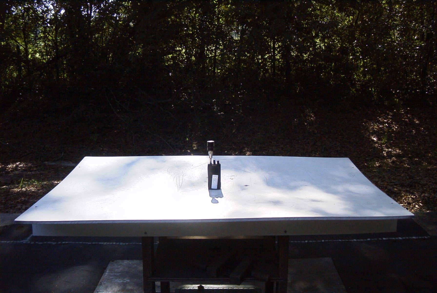
TIMCO ENGINEERING INC. 849 NW State Road 45 Newberry, Florida 32669 http://www.timcoengr.com 888.472.2424 F 352.472.2030 email: [email protected] APPLICANT: MIDLAND RADIO CORP. FCC ID: MMAPL150 REPORT #: M\MIDLAND_O7K\1065UT6\1065UT6TestReport.doc COVER SHEET Test Report Product Name: VHF RADIO FCC ID: MMAPL150 Applicant: MIDLAND RADIO CORP. 1120 CLAY STREET NORTH KANSAS CITY MISSOURI 64116 USA Date Receipt: 5/19/2006 Date Tested: 6/19/2006 TIMCO ENGINEERING INC. 849 NW State Road 45 Newberry, Florida 32669 http://www.timcoengr.com 888.472.2424 F 352.472.2030 email: [email protected] APPLICANT: MIDLAND RADIO CORP. FCC ID: MMAPL150 REPORT #: M\MIDLAND_O7K\1065UT6\1065UT6TestReport.doc TABLE OF CONTENTS TABLE OF CONTENTS LIST APPLICANT: MIDLAND RADIO CORP. FCC ID: MMAPL150 TEST REPORT: PAGE 1...........GENERAL INFORMATION & TECHNICAL DESCRIPTION PAGE 2...........TECHNICAL DESCRIPTION CONTINUED RF POWER OUTPUT PAGE 3...........MODULATION CHARACTERISTICS AUDIO FREQUENCY RESPONSE PAGE 4-5.........AUDIO LOW PASS FILTER PLOTS PAGE 6-7.........MODULATION LIMITING PLOTS PAGE 8-11........OCCUPIED BANDWIDTH PAGE 12..........SPURIOUS EMISSIONS AT ANTENNA TERMINALS PAGE 13..........METHOD OF MEASURING SPURIOUS EMISSIONS AT ANTENNA TERMINALS PAGE 14-15.......FIELD STRENGTH OF SPURIOUS EMISSIONS PAGE 16..........METHOD OF MEASURING RADIATED SPURIOUS EMISSIONS PAGE 17..........FREQUENCY STABILITY PAGE 18-19.......TRANSIENT FREQUENCY STABILITY PAGE 20..........EQUIPMENT LIST EXHIBITS CONTAINING: BLOCK DIAGRAM SCHEMATIC PARTS LIST USERS MANUAL LABEL SAMPLE LABEL LOCATION EXTERNAL PHOTOGRAPHS INTERNAL PHOTOGRAPHS TUNING PROCEDURE OPERATIONAL DESCRIPTION TEST SET UP PHOTOGRAPH TIMCO ENGINEERING INC. 849 NW State Road 45 Newberry, Florida 32669 http://www.timcoengr.com 888.472.2424 F 352.472.2030 email: [email protected] APPLICANT: MIDLAND RADIO CORP. FCC ID: MMAPL150 REPORT #: M\MIDLAND_O7K\1065UT6\1065UT6TestReport.doc Page 1 of 20 GENERAL INFORMATION REQUIRED FOR CERTIFICATION OF A LICENSED TRANSMITTER Part 2.1033(c)(1)(2) MIDLAND RADIO CORP. will manufacture the FCCID: MMAPL150 VHF TRANSCEIVER in quantity for use under FCC RULES PART 90. MIDLAND RADIO CORP. 1120 CLAY STREET NORTH KANSAS CITY, MISSOURI 64116 USA This approval covers 2 radio models – Model PL2215 and PL2415 which are electronically the same except one is a 2 channel radio and one is a 4 channel radio. Part 2.1033(c) TECHNICAL DESCRIPTION Part 2.1033(c)(3) Instruction book. A copy of the instruction manual is included in the exhibits. Part 2.1033(c)(4) Type of Emission: 11K0F3E Part 90.209 Part 90.207 Bn = 2M + 2DK M = 3000 D = 2500 Bn = 2(3000)+2(2500) = 11.0K Type of Emissions: 16K0F3E Bn = 2M + 2DK M = 3000 D = 5000 Bn = 2(3000)+2(5000) = 16.0K Part 2.1033(c)(5) Frequency Range: 148-174 Part 90.209 (b)(5) Part 2.1033(c)(6)(7) Power Output shall not exceed 59 Watts into a 50 ohm Part 90.205 resistive load. There are no user power controls. Part 2.1033(c)(8) DC Voltages and Current into Final Amplifier: POWER INPUT: FINAL AMPLIFIER ONLY INPUT …
Text truncated - open the document above for the full version.
Contact Information
Applicant
Butch Rittmann(Director of Operations)
Test Firm
Timco Engineering, Inc.Sid Sanders
Technical Specifications
| # | Rule Parts | Frequency Range | Power Output | Emission | Tolerance |
|---|---|---|---|---|---|
| 2 | 90,90.21 | 148 MHz - 174 MHz | 2.3 W | 16K0F3E | 2.5 ppm |
Other Applications from Midland Radio Corporation

MMAMXMC95
Jun 10, 2026Wireless Bluetooth Microphone
Equipment Class
JAB - Part 15 Class B Digital Device
MMAMXT295
Jun 08, 2026GMRS Radio
Equipment Class
TNF - Licensed Non-Broadcast Transmitter Held to Face
MMACLIPTALK
Apr 27, 2026Transceiver
Equipment Class
DTS - Digital Transmission System
MMABR200S
Jan 13, 2026BUSINESS BAND TWO-WAY RADIO
Equipment Class
TNF - Licensed Non-Broadcast Transmitter Held to Face
MMAGXT67
Oct 29, 2023GMRS RADIO
Equipment Class
TNF - Licensed Non-Broadcast Transmitter Held to Face