MMARG1MARINE MOBILE TRANSCEIVER
Midland Radio Corporation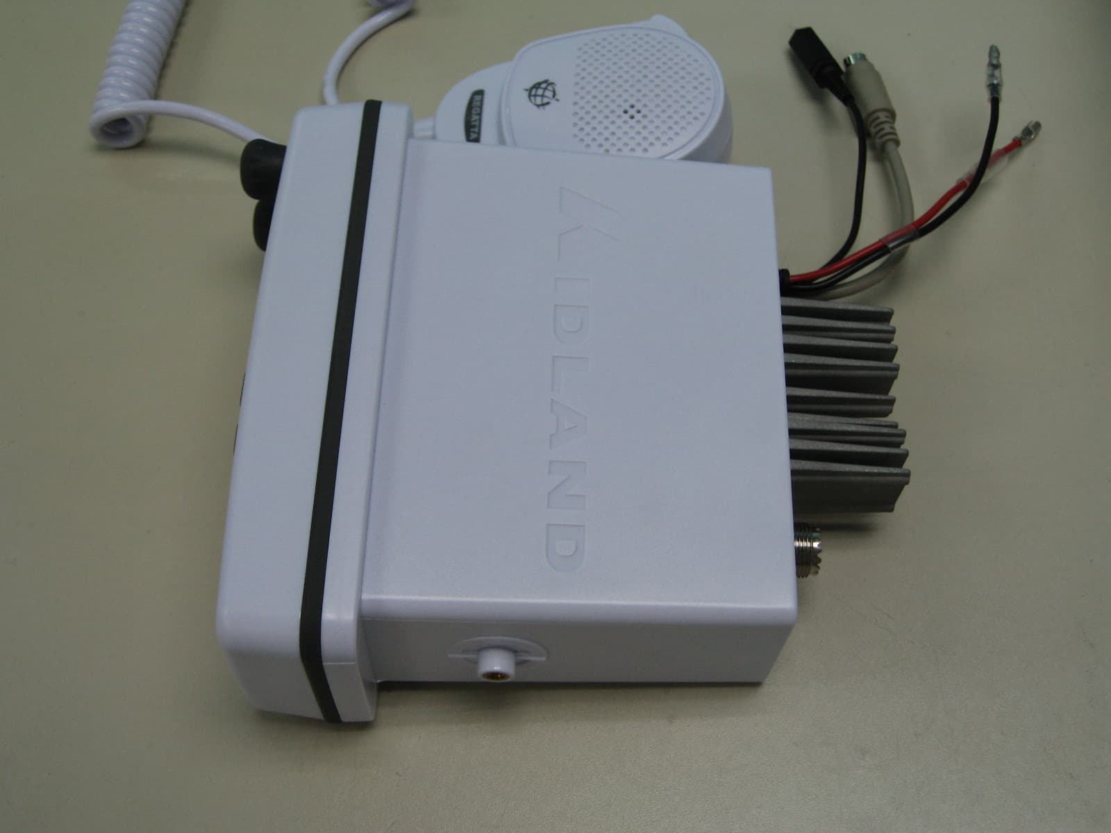
Click to zoom
Application Details
- Equipment Class
- TNB - Licensed Non-Broadcast Station Transmitter
- Date of Grant
- May 14, 2007
- Application Purpose
- Original Equipment
- Date of Application
- May 14, 2007
- Equipment Note
- MARINE MOBILE TRANSCEIVER
- Frequency Range
- 156.02500000 - 157.42500000
- Company
- Midland Radio Corporation
- Country
- United States
Documents & Files
Document Text
Text extracted from the exhibit documents filed with the FCC. Open a document above to read the original.
Users Manual
Fixed Mount VHF Marine Radio Fixed Mount VHF Marine Radio with DSC with DSC Owner’s Manual Owner’s Manual ww ww ww ww ww ww .. .. mm mm ii ii dd dd ll ll aa aa nn nn dd dd rr rr aa aa dd dd ii ii oo oo .. .. cc cc oo oo mm mm Model RG1 Owner’s Manual Page 2www.midlandradio.com Table of Contents Table of Contents Welcome to the World of Midland Electronics Major REGATTA 1 Features FCC Licensing Information - Station License - International Station License - Radio Call Sign - Canadian Ship Station License Warnings Included with your REGATTA 1 Controls and Indicators -Front Panel -Back Panel -LCD Indicators Installation Operation Distress Digital Selective Calling GPS Input Connection Specification USA Channel and Function Chart International Channel and Function Chart Canada Channel and Function Chart Technical Specifications Trouble Shooting Care and Maintenance Limited Warranty Service and Technical Support Other Midland Products 2 3 3 4 4 4 4 4 5 6 7 7 8 8 9-10 11-13 14 15 16 17 18 19 20 21 22 23 24 25 Model RG1 Owner’s Manual Page 3www.midlandradio.com Welcome to the World of Midland Electronics Welcome to the World of Midland Electronics Congratulations on your purchase of the Midland REGATTA 1 VHF Marine Radio. This fixed mount radio gives you 2- way vessel to vessel and vessel to shore communica- tion- for both safety and navigational purposes. With the REGATTA 1, you can call for help, get information from other boaters and talk to lock or bridge tenders. In addi- tion, in the USA you can access the NOAA weather broadcast with the 10 weather channels and be alerted to severe weather emergencies with the weather alert fea- ture. The REGATTA 1 is a quality piece of electronic equipment, skillfully constructed with the finest components. This radio is designed for reliable and trouble-free per- formance for years to come. Enjoy! Major REGATTA 1 Features: Major REGATTA 1 Features: • Submersible- meets JIS7 specifications • All Marine Channels-US, International and Canada • 10 NOAA Weather Channels • NOAA Weather Alert • DSC Digital Selective Calling – for security on the water and the ability to make quick calls automatically. • Channel Scan • HI/LO Power Settings • Last Channel Memory • Tri-Watch • Large, High Visibility Display • PA Function • Distress Button • Instant Emergency Channel 16/9-for instant access to channel 16 (the universal marine channel for emergency contact). • Front Firing Speaker • NMEA connection – use the interface cable supplied for easy connection from transceiver to optional GPS system. Once connected, the display will show the automatically updated coordinates (latitude and longitude) and time data. • Connection to an external speaker (optional) – for listening to communications further away from the transceiver. In an effort to constantly improve product quality, product characteristics are subject to change without notice. Model RG1 Owner’s Manual Page 4www.midlandradio.com Registration of your Marine Transceiver For using GMDSS and DSC functions, the operator must have a GMDSS radio operator's certificate (SRC or LRC) and apply for a ships MMSI number at the local radio authority. Without MMSI number the radio can only be used as conventional VHF marine radio without DSC. Your distributor may program your radio according to your needs. FCC Licensing Information FCC Licensing Information The REGATTA 1 radio complies with the FCC (Federal Communication Commission) requirements that regulate the Maritime Radio Service. This radio incorpo- rates a VHF FM transceiver designed for use in the frequency range of 156.025 to 163.275 MHz. It requires 13.8 volts DC and has a switchable RF output power of one (1) or 25 watts. The transceiver is capable of DSC (Digital Selective Calling) operation. The radio operates on all currently allocated marine channels and is switchable for use- according to U.S.A., International, or Canadian regulations. Station License An FCC ship station license is no longer required for any vessel traveling in U.S.A. waters which uses a VHF marine radio, RADAR, or EPIRB (Emergency Position Indicating Radio Beacon), and which is not required to carry radio equipment. However, any vessel required to carry a marine radio on an international voyage, carry- ing a HF single side band radiotelephone, or carrying a marine satellite terminal must obtain a station license. FCC license forms and applications for ship and land stations can be downloaded through the Internet at www.fcc.gov/forms. Forms can also be obtained by calling the FCC at 888-225-5322. International Station License If your vessel will be entering the sovereign waters of a country other than the U.S.A. or Canada, you should contact that country’s communications regulatory authori- ty for licensing information. Radio Call Sign Currently, the FCC does not require recreational boaters to have a license. The United States Coast Guard recommends that the boat’s registration number and state of registry (e.g., Illinois 1234 AB) be used as a call sign and be clearly visible on the ves- sel. Canadian Ship Station License You need a Radio Operator’s Certificate if your vessel is operated in Canadian waters. Radio Operator training and certification is available from the Canadian Power Squadron. Visit their website (http://www.cps-ecp.ca/english/newradiocard.html), contact the nearest field office or write: Industry of Canada, Radio Regulatory Branch, Attn: DOSP, 300 Slater Street, Ottawa, Ontario, Canada K1A 0C8. Model RG1 Owner’s Manual Page 5www.midlandradio.com Warnings Warnings General This device has been tested for compliance with Class D digital marine device limits. These limits were created to allow for reasonable protection against damaging interference. This device is to be used solely as an aid to navigation. Its settings may be influenced by diverse factors, such as defects or malfunction of the device, environ- mental conditions or improper use. It is the user's responsibility …
Text truncated - open the document above for the full version.
Cover Letter(s)
5900 Parretta Drive ● KANSAS CITY, MISSOURI ● 64120 TELEPHONE: (816) 241-8500 ● FAX: (816) 241-5713 EMAIL: [email protected] WEBSITE: www.midlandradio.com Federal Communications Commission Authorization and Evaluation Division Confidentiality Request regarding application for certification of FCC ID: MMARG1 Pursuant to Sections 0.457 and 0.459 of the Commission’s Rules, we hereby request confidential treatment of information accompanying this application as outlined below: Schematic Block Diagram Operational description Adjustment Procedure The above materials contain trade secrets and proprietary information not customarily released to the public. The public disclosure of these materials may be harmful to the applicant and provide unjustified benefits to its competitors. The applicant understands that pursuant to Section 0.457 of the Rules, disclosure of this application and all accompanying documentation will not be made before the date of the Grant for this application. Sincerely, Thomas Bishop, Consumer Product Engineer April 11, 2007 Midland Radio Corporation 5900 Parretta Drive, Kansas City, MO. 64120 Phone: (816) 241-8500 Fax: (816) 241-5713 Website: wwwl.midlandradio.com E-Mail: [email protected]
RF Exposure Info
FCC RF Exposure Requirements General information: FCC ID: Device category: Mobile per Part 2.1091 Environment: Uncontrolled Exposure Mobile devices that operate under Part 80 of this chapter are subject to routine environmental evaluation for RF exposure prior to equipment authorization or use if they operate at frequencies of 1.5 GHz or below and their effective radiated power (ERP) is 1.5 watts or more. However, compliance with the power density limits of 1.1310 is not required. Antenna: The manufacturer does specify an antenna with a gain of 3 dBi to be used with this device. This device has provisions for operation in a vehicle, or a fixed location. Configuration Antenna p/n Type Max. Gain (dBi) Boat Any omni 3 Operating configuration and exposure conditions: The conducted output power is 25 Watts. Typical use qualifies for a maximum duty cycle factor of 50%. - Part 2.1091 states that devices are excluded from routine evaluation if the EIRP is less than 2.46Watt (or 1.5WERP). - Vehicle Operation: The maximum antenna gain that can be used is 3dBi. A coaxial cable of the type RG 58 has a loss of 1dB for a length of 15 feet. MPE Calculation: The minimum separation distance is calculated as follows: The limit for general uncontrolled exposure environment below 300 MHz is 0.2 mW/cm 2 . 4/27/2007 Page 1 of 3 FCC ID: Channel frequency: 156.025-157.425 MHz The conducted power output is 25 watt. The coax loss was taken as 1 dB. Antenna gain was taken as 3 dBi 50% talk time in 30 minutes antenna gain in dBd S f 1500 := power density limit for uncontrolled exposure G1dBd2.15+:= gain in dBi G13=dBi S0.2= CL1:= dB coax loss GG1CL−:= gain numeric Gn10 G 10 := Gn1.585=dB R PoGn⋅() 4π⋅S⋅ () := inches R 2.54 := R88.784= distance in centimeters required for compliance inches34.954= W25:= power in Watts D1:= Duty Factor in decimal % (1=100%) 1 for FM E15:= exposure time in minutes U30:= (use 6 for controlled and 30 for uncontrolled ) WexpWD⋅ E U ⎛ ⎜ ⎝ ⎞ ⎠ ⋅:= PC E U ⎛ ⎜ ⎝ ⎞ ⎠ 100⋅:= Wexp12.5=WattsPC50= % on time _____________________________________________________________________________ Po12500:=mWatts f300:= Frequency in MHz dBd.85:= 4/27/2007 Page 2 of 3 FCC ID: Conclusion: The device complies with the MPE requirements by providing a safe separation distance of 89 cm between the antenna, including any radiating structure, and any persons when normally operated . Proposed RF exposure safety information to include in User’s Manual: “FCC RF Exposure Requirements: CAUTION: The antenna(s) used for this transmitter must not be co-located or operating in conjunction with any other antenna or transmitter. This device is approved with emissions having a source-based time- averaging duty factor not exceeding 50%. The safe operating distance between the general population and the antenna when transmitting is 35 inches. Failure to observe these restrictions will result in exceeding the FCC RF exposure limits. 4/27/2007 Page 3 of 3 FCC ID:
Test Report
TIMCO ENGINEERING INC. 849 NW State Road 45 Newberry, Florida 32669 http://www.timcoengr.com 888.472.2424 F 352.472.2030 email: [email protected] APPLICANT: MIDLAND RADIO CORPORATION FCC ID: MMARG1 REPORT #: M\MidlandRadio_MMA\569AUT7\569AUT7TestReport.doc COVER SHEET Test Report Product Name: MARINE MOBILE TRANSCEIVER FCC ID: MMARG1 Applicant: MIDLAND RADIO CORPORATION 5900 PARRETTA DRIVE KANSAS CITY MISSOURI 64120 USA Date Receipt: 3/9/2007 Date Tested: 4/4/2007 TIMCO ENGINEERING INC. 849 NW State Road 45 Newberry, Florida 32669 http://www.timcoengr.com 888.472.2424 F 352.472.2030 email: [email protected] APPLICANT: MIDLAND RADIO CORPORATION FCC ID: MMARG1 REPORT #: M\MidlandRadio_MMA\569AUT7\569AUT7TestReport.doc TABLE OF CONTENTS TABLE OF CONTENTS LIST APPLICANT: MIDLAND RADIO CORPORATION FCC ID: MMARG1 TEST REPORT: PAGE 1............GENERAL INFORMATION & TECHNICAL DESCRIPTION PAGE 2............TECHNICAL DESCRIPTION CONTINUED RF POWER OUTPUT PAGE 3............TECHNICAL DATA PAGE 4............VOICE MODULATION CHARACTERISITICS AUDIO FREQUENCY RESPONSE PAGE 5............AUDIO LOW PASS FILTER PAGE 6............MODULATION LIMITING PAGE 7............OCCUPIED BANDWIDTH PAGE 8............OCCUPIED BANDWIDTH PLOT PAGE 9............OCCUPIED BANDWIDTH PLOT - DSC PAGE 10...........SPURIOUS EMISSIONS AT ANTENNA TERMINALS PAGE 11...........METHOD OF MEASURING CONDUCTED SPURIOUS EMISS PAGE 12...........FIELD STRENGTH OF SPURIOUS EMISSIONS PAGE 13...........METHOD OF MEASURING RADIATED SPURIOUS EMISSIONS PAGE 14...........FREQUENCY STABILITY PAGE 15...........LIST OF TEST EQUIPMENT EXHIBITS INCLUDING: BLOCK DIAGRAM SCHEMATIC PARTS LIST USERS MANUAL LABEL SAMPLE LABEL LOCATION EXTERNAL PHOTOGRAPHS INTERNAL PHOTOGRAPHS OPERATIONAL DESCRIPTION TUNING PROCEDURE TEST SET UP PHOTOGRAPHS TIMCO ENGINEERING INC. 849 NW State Road 45 Newberry, Florida 32669 http://www.timcoengr.com 888.472.2424 F 352.472.2030 email: [email protected] APPLICANT: MIDLAND RADIO CORPORATION FCC ID: MMARG1 REPORT #: M\MidlandRadio_MMA\569AUT7\569AUT7TestReport.doc Page 1 of 15 GENERAL_INFORMATION 2.1033(c) MIDLAND RADIO CORPORATION will sell the FCC ID: MMARG1 VHF Marine transmitter in quantity, for use under FCC RULES PART 80. 2.1033(c) TECHNICAL_DESCRIPTION (4) Type of Emission: 16K0G3E/16K0F3E Bn = 2M + 2DK M = 3000 D = 4.6kHz (Peak Deviation) K = 1 Bn = 2(3.0k) + 2(4.6k)(1) = 6.0k + 9.2k = 15.2k 80.205 (a) ALLOWED AUTHORIZED BANDWIDTH = 20.00kHz. (5) Type of Emission: 16K0G3E/16K0F3E Bn = 2M + 2DK M = 3000 D = 4.6kHz (Peak Deviation) K = 1 Bn = 2(3.0k) + 2(4.6k)(1) = 6.0k + 9.1 = 15.2.0k 80.205 (a) ALLOWED AUTHORIZED BANDWIDTH = 20.00kHz. 2.1033(c)(6) Frequency Range: 156.025 – 157.425 MHz 2.1033(c)(7) Power Range and Controls: There is a user Power switch for High/Low Power. Maximum Output Power Rating: High (25) Watts, (1) Watt into a 50 ohm resistive load. 2.1033(c)(8) DC Voltages and Current into Final Amplifier: POWER INPUT FINAL AMPLIFIER ONLY High Low Vce = 13.6 Volts Vce = 13.6 VDC Ice = 5.66 A. Ice = 1.51 Pin = 76.97 Watts Pin = 20.53 Watts TIMCO ENGINEERING INC. 849 NW State Road 45 Newberry, Florida 32669 http://www.timcoengr.com 888.472.2424 F 352.472.2030 email: [email protected] APPLICANT: MIDLAND RADIO CORPORATION FCC ID: MMARG1 REPORT #: M\MidlandRadio_MMA\569AUT7\569AUT7TestReport.doc Page 2 of 15 2.1033(c)(9) Complete Circuit Diagrams: The circuit and block diagrams are included. 2.1033(c)(10) Instruction book. The instruction manual is included. 2.1033(c)(11) Tune-up procedure. The tune-up procedure is included. Description of all circuitry and devices provided for determining and stabilizing frequency is included in the circuit description 2.1033(c)(11) Digital modulation. This unit does NOT use digital modulation. The data required by 2.1046 through 2.1055 is submitted below. 2.1046(a) RF_power_output . 80.215 (e)(1) RF power is measured by connecting a 50 ohm, re- sistive wattmeter to the RF output connector. With a nominal battery voltage, and the transmitter properly adjusted the RF output measures: OUTPUT POWER: HIGH: 25 W CONDUCTED LOW: 1 W CONDUCTED 80.911 (d)(5) For primary supply voltages, measured in accordance with the procedures in this paragraph, greater than 11.5 volts, but less than 12.6 volts, the required transmitter output power shall be equal or greater than the value calculated below P = 4.375(v) – 35.313 (For 12V this equals 17.2W) METHOD OF MEASURING RF POWER OUTPUT Transmitter 50 ohm under test Resistive Wattmeter Power Supply TIMCO ENGINEERING INC. 849 NW State Road 45 Newberry, Florida 32669 http://www.timcoengr.com 888.472.2424 F 352.472.2030 email: [email protected] APPLICANT: MIDLAND RADIO CORPORATION FCC ID: MMARG1 REPORT #: M\MidlandRadio_MMA\569AUT7\569AUT7TestReport.doc Page 3 of 15 TECHNICAL DATA: 80.203 (b) External Controls: The transmitter is capable of changing frequency between 156.05 – 157.425 MHz by external control. The available channels are shown in the User Manual description Channel List. These channels are preprogrammed by the manufacturer and change of frequency is inaccessible to the station operator. 80.203 (c) Five minutes continuous transmission test. The antenna was connected to a dummy load and the radio was locked in a transmit PTT mode. An external timer digital clock was used to observe the duration of the un-modulated transmission. The transmitter turned off and the radio went to receive mode at 4 minutes, 58 seconds as displayed by the external digital clock. 80.203 (n) This radio complies with the requirement for DSC capability in the 156 – 162 MHz band and in accordance with 80.225. 80.873; 80.956 Transmitter G3E emission capability: The transmitter was connected to 50 ohm resistive wattmeter and the frequency was set to 156.300 and to 156.800 MHz. With normal modulation, the output power displayed was 25 Watts at the high power setting and 1 watt at low power setting, consistent with previous measurements. The transmitter has been demonstrated to b…
Text truncated - open the document above for the full version.
Contact Information
Applicant
Butch Rittmann(Director of Operations)
Test Firm
Timco Engineering, Inc.Sid Sanders
Technical Specifications
| # | Rule Parts | Frequency Range | Power Output | Emission | Tolerance |
|---|---|---|---|---|---|
| 4 | 8 | 156.025 MHz - 157.425 MHz | 1 W | 16K0F3E | 10 ppm |
Other Applications from Midland Radio Corporation

MMAMXMC95
Jun 10, 2026Wireless Bluetooth Microphone
Equipment Class
JAB - Part 15 Class B Digital Device
MMAMXT295
Jun 08, 2026GMRS Radio
Equipment Class
TNF - Licensed Non-Broadcast Transmitter Held to Face
MMACLIPTALK
Apr 27, 2026Transceiver
Equipment Class
DTS - Digital Transmission System
MMABR200S
Jan 13, 2026BUSINESS BAND TWO-WAY RADIO
Equipment Class
TNF - Licensed Non-Broadcast Transmitter Held to Face
MMAGXT67
Oct 29, 2023GMRS RADIO
Equipment Class
TNF - Licensed Non-Broadcast Transmitter Held to Face