MMASD250U2UHF Data Radio
Midland Radio Corporation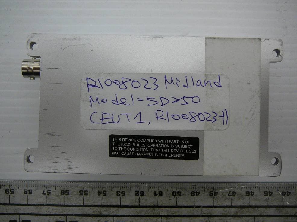
Click to zoom
Application Details
- Equipment Class
- TNB - Licensed Non-Broadcast Station Transmitter
- Date of Grant
- Sep 08, 2010
- Application Purpose
- Original Equipment
- Date of Application
- Sep 08, 2010
- Equipment Note
- UHF Data Radio
- Frequency Range
- 440.00000000 - 480.00000000
- Company
- Midland Radio Corporation
- Country
- United States
Documents & Files
Document Text
Text extracted from the exhibit documents filed with the FCC. Open a document above to read the original.
Users Manual
SD-250 User Guide Rev. 0B 1 Contents Introduction --- 2 Preparing for use Unpacking and inspection --- 3 Description of modem --- 4 Features --- 5 External Connections --- 6 Pin Outs --- 7 Operation Channel Selection --- 9 Transmit/Receive Operation --- 10 Serial Commands --- 10 Status Indicators --- 12 Programming --- 13 Installation Antennas --- 14 Power sources --- 14 Cabling --- 15 Fixing --- 15 Safety and general information --- 16 Warranty and repairs --- 18 Care of the equipment --- 18 Disposal / Recycling --- 18 Rev. 0B 2 Introduction The SD250 range is a 1 to 6 Watts RF data module at VHF and UHF frequencies. The SD250 is housed in a rugged cast-aluminum box sealed to IEC 529 (IP54) making it suitable for a wide range of mobile and fixed applications. All SD250 RF data module units meet the essential requirements of the relevant directives. In order to maintain this compliance the installation and safety information must be adhered to at all times. • The SD250 RF data module must only be installed where unintentional contact cannot be made. The surface of the device may be hot to touch under certain transmit conditions. The SD250 is not designed for permanent transmission. If prolonged transmission periods are used, the unit will become hot and will require an additional heat-sink to be fitted. • When fitting the module into a fixed installation, care must be taken in the routing of all cabling such that the insulation cannot become damaged. • The recommended supply sources for use with the SD250 is a standard 12V / 2A dc supply, but is capable of operating in the range 9V - 18V. Rev. 0B 3 Preparing for use Unpacking and inspection Unpack the modem and check that you have received the following items: • SD250 RF data module • User Guide (this document) If any of these items are missing, please contact your supplier. Rev. 0B 4 Description of modem The SD250 is a network free, point to point RF data module that offers great flexibility in varied applications where wireless data or voice communication is needed. It can be used as a transparent radio, with no internal modem fitted, to allow users to facilitate the use of their own modem and protocol. The correct signal levels need to be used with the use of separate control lines, see the pin out table below. The SD250 can also be fitted with below a few different modems • Bell 202 / V.23 modem (1200 baud rate) • FFSK modem (4800 baud rate) • GMSK modem (9600 baud rate) The internal modem allows communication with a pc using RS 232 for the data and control lines. For further details, please refer to the modem manual. SD250 has standard radio features available which are associated with a private radio. This includes CTCSS and DCS, software controlled squelch, time out timer options and busy channel lockout as listed below (not all available with option modem fitted). There is a microphone input and speaker output to allow speech to be transmitted and received. Rev. 0B 5 Features • Compact and rugged die cast box • Resistant to dirt, dust and water ingress (IP54 rated) • Network free, point to point communication • 1 / 6 watt programmable output power • Synthesized operation with 16 channel capability • SAT when used with Bell 202 / V.23 and FFSK modem or speech • Programmable 12.5 / 25kHz channel spacing • External modem / Direct FM • Internal modem options available: Bell 202 / V.23, FFSK, GMSK • ‘Busy’ output (can be set active high or low) • 9 – 18 volt supply input • Busy Channel lockout • Time out timer Rev. 0B 6 External Connections 1. HD 9-way d-type (data, control signals and power supply) 2. BNC antenna connector Rev. 0B 7 Pin Outs 1 5 96 Busy Detect Mic Input Prog. Data Input Speaker Output Mod. Input (Data) Demod. Output (Data) PTT / Prog. Data Output GND B+ DB-9 PIN OUT table with input and output levels D-Type Pin No. Function Description Signal Type Input/ Output Data modulation IN (Tx Mod) Default : AC coupled signal directly injected to MOD through data low pass filter without pre-emphasis. Direct Modulation(includes POCSAG) : DC coupled signal directly injected to MOD. No data filter and pre-emphasis on signal path. Direct FM MOD. is selected by PC program. Link 409 fitted. Link 412 not fitted. Default : Analog signal 1KHz audio at 60% peak system deviation input level = 100 to 120mVrms Direct FM : TTL level 1 RS 232 data IN Input to Bell 202/V23, FFSK, GMSK modem. Link 409 not fitted and link412 fitted. RS-232 level (option) +12V = Tx -12V = Rx I/P Data unfiltered OUT (RX disc) Discriminator audio from the SD-250. This is the unprocessed AF signal prior to tone filtering and de-emphasis. Link 413 fitted and link 414 not fitted. Analog signal 1KHz audio at 60% peak system deviation produces 200 to 300mVrms 2 RS 232 data OUT Output from Bell 202/V23, FFSK, GMSK modem. Link 413 not fitted and link 414 fitted RS-232 level (option) +12V = Tx -12V = Rx O/P 3 PTT In (Tx Key) / Signal, which keys the transmitter, is an active low input with an internal pull up resistor. If required, the pin can be converted to active high using link options. TTL level 0V = Tx o/c = Rx I/P / Rev. 0B 8 Program: Read Note: If the option modem board is installed, a resistor link can select RS-232 signal levels. See Modem manual Program : READ used for outputting programming data from mode RS-232 level (option) +12V = Tx -12V = Rx TTL level only for radio program O/P 4 Ground Ground connection to chassis of the radio. 0V (Chassis) 5 B+ Power supply input (Nominal 12V) 9.0V – 18.0V DC 6 Busy (CD) Logic level output to indicate presence of a carrier. (If required, link changes enable the busy line to be active high) Note: If the option modem board is installed, a resistor link can select RS-232 signal levels. See Modem manual. TTL level 0V = carrier 5V = no carrier RS-232 level (option) +12V = carrier -12V = no carrier O/P 7 Microphone filtered audio IN Audio signal that is filtered (high pass and pre-emphasis) then follows same route as data mod…
Text truncated - open the document above for the full version.
Cover Letter(s)
5900 Parretta Drive ● KANSAS CITY, MISSOURI ● 64120 TELEPHONE: (816) 241-8500 ● FAX: (816) 241-5713 EMAIL: [email protected] WEBSITE: www.midlandradio.com FCC Confidential Authorization July 22, 2010 FEDERAL COMMUNICATIONS COMMISSIONS Authorization and Evaluation Division 7435 Oakland Mills Road Columbia, MD 21046 Subject: Confidentiality Request regarding application for certification of FCC ID: MMASD250U2 In accordance with Sections 0.457 and 0.459 of the Commission’s Rules, Midland Radio Corporation. hereby requests long-term confidential treatment of information accompanying this application as outlined below: • Block Diagram • Schematics • Operation Description The above materials contain proprietary and confidential information not customarily released to the public. The public disclosure of these materials provides unjustified benefits to its competitors in the market. Sincerely, David Kingsolver, Director of Engineering Midland Radio Corporation 5900 Parretta Drive Kansas City, MO 64120 (816) 241-8500 (ext 237)
External Photos
Midland Radio Corporation FCC ID: MMASD250U2, IC: 3690A-SD250U2 Report No.: R1008023-90 Page 61 of 66 FCC Part 90 & IC RSS-119 Test Report 15 EXHIBIT C - EUT Photographs 15.1 EUT - Top View 15.2 EUT – Bottom View Midland Radio Corporation FCC ID: MMASD250U2, IC: 3690A-SD250U2 Report No.: R1008023-90 Page 62 of 66 FCC Part 90 & IC RSS-119 Test Report 15.3 EUT - Port View
Internal Photos
Midland Radio Corporation FCC ID: MMASD250U2, IC: 3690A-SD250U2 Report No.: R1008023-90 Page 63 of 66 FCC Part 90 & IC RSS-119 Test Report 15.4 EUT - Cover off Top View 15.5 EUT- Digital PCB Board Top View Midland Radio Corporation FCC ID: MMASD250U2, IC: 3690A-SD250U2 Report No.: R1008023-90 Page 64 of 66 FCC Part 90 & IC RSS-119 Test Report 15.6 EUT- Digital PCB Board Bottom View 15.7 EUT- RF PCB Board (Shielded) Top View Midland Radio Corporation FCC ID: MMASD250U2, IC: 3690A-SD250U2 Report No.: R1008023-90 Page 65 of 66 FCC Part 90 & IC RSS-119 Test Report 15.8 EUT- RF PCB Board (Shielded) Bottom View 15.9 EUT- RF PCB Board (Unshielded) Top View Midland Radio Corporation FCC ID: MMASD250U2, IC: 3690A-SD250U2 Report No.: R1008023-90 Page 66 of 66 FCC Part 90 & IC RSS-119 Test Report 15.10 EUT- RF PCB Board (Unshielded) Bottom View ***** END OF REPORT *****
RF Exposure Info
Midland Radio Corporation FCC ID: MMASD250U2, IC: 3690A-SD250U2 Report No.: R1008023-90 Page 10 of 66 FCC Part 90 & IC RSS-119 Test Report 4 FCC §2.1091 & IC RSS-102 - RF Exposure 4.1 Applicable Standards FCC §2.1091 (a) Requirements of this section are a consequence of Commission responsibilities under the National Environmental Policy Act to evaluate the environmental significance of its actions. See subpart I of part 1 of this chapter, in particular §1.1307(b). According to §1.1310 and §2.1091 RF exposure is calculated. Limits for Exposure Frequency Range (MHz) Electric Field Strength (V/m) Magnetic Field Strength (A/m) Power Density (mW/cm 2 ) Averaging Time (minutes) (A) Limits for Occupational/Controlled Exposures 0.3-3.0 614 1.63 *(100) 6 3.0-30 1842/f 4.89/f *(900/f 2 ) 6 30-300 61.4 0.163 1.0 6 300-1500 / / f/300 6 1500-100,00 / / 1 6 (B) Limits for General Population/Uncontrolled Exposure 0.3-1.34 614 1.63 *(100) 30 1.34-30 842/f 2.19/f *(180/f 2 ) 30 30-300 27.5 0.073 0.2 30 300-1500 / / f/150 30 1500-100,000 / / 1 30 f = frequency in MHz * = Plane-wave equivalent power density Note 1 to Table 1: Occupational/controlled limits apply in situations in which persons are exposed as a consequence of their employment provided those persons are fully aware of the potential for exposure and can exercise control over their exposure. Limits for occupational/controlled exposure also apply in situations when an individual is transient through a location where occupational/controlled limits apply provided he or she is made aware of the potential for exposure. Note 2 to Table 1: General population/uncontrolled exposures apply in situations in which the general public may be exposed, or in which persons that are exposed as a consequence of their employment may not be fully aware of the potential for exposure or can not exercise control over their exposure. Midland Radio Corporation FCC ID: MMASD250U2, IC: 3690A-SD250U2 Report No.: R1008023-90 Page 11 of 66 FCC Part 90 & IC RSS-119 Test Report According to IC RSS-102 Issue 2 section 4.4, RF Field Strength Limits for Controlled Use Devices (Controlled Environment). Frequency Range (MHz) Electric Field (V/m rms) Magnetic Field (A/m rms) Power Density (W/m 2 ) Time Averagi ng (min) 0.003 - 1 600 2.19 - 6 1 - 10 600 / f 4.9 / f - 6 10 - 30 60 4.9 / f - 6 30 – 300 60 0.163 10* 6 300 – 1 500 3.54 f 0.5 0.0094f 0.5 f/30 6 1 500 – 15 000 137 0.364 50 6 15 000 – 150 000 137 0.364 50 616000 / f 1.2 150 000- 300 000 0.354f 0.5 9.4 x10 -4 f 0.5 3.33 x 10 -4 f 616000 / f 1.2 Note: ƒ is frequency in MHz * = Power density limit is applicable at frequencies greater than 100 MHz Antenna: The manufacturer does not specify an antenna. A typical vehicle antenna has a gain of 6 dBi was used with this device.This device has provisions for operation in a vehicle, or a fixed location . Operating Cionfiguration and exposure conditions: Device category: Mobile per Part 2.1091 Environment: Controlled Exposure Typical use qualifies for a maximum duty cycle factor of 50%. The manufacturer also markets this device only for occupation use. - Vehicle Operation: A typical vehicle installation consists of an antenna system with a coaxial cable of the type RG 58 which has a loss of 1 dB for a length of 15 feet. MPE Prediction Predication of MPE limit at a given distance, Equation from OET Bulletin 65, Edition 97-01 S = PG/4πR² Where: S = power density P = power input to antenna G = power gain of the antenna in the direction of interest relative to an isotropic radiator R = distance to the center of radiation of the antenna Midland Radio Corporation FCC ID: MMASD250U2, IC: 3690A-SD250U2 Report No.: R1008023-90 Page 12 of 66 FCC Part 90 & IC RSS-119 Test Report Note: The conducted power output is 5.956 watt, the coax loss was taken as 1 dB, and Antenna gain was taken as 6 dBi, 50% talk time in 6 minutes Conclusion The device complies with the MPE requirements by providing a safe separation distance of 25 cm between the antenna, including any radiating structure, and any persons when normally operated. Proposed RF exposure safety information to include in User’s Manual: “FCC RF Exposure Requirements”: CAUTION: The antenna(s) used for this transmitter must not be co-located or operating in conjunction with any other antenna or transmitter. This device is approved with emissions having a source-based timeaveraging duty factor not exceeding 50%. Vehicle – Antenna Installation: - Antennas used for this transmitter must not exceed an antenna gain of 6 dBi - For rear deck trunk and roof top installations, the antenna must be located at least 25 cm away from rear- seat passengers and bystanders in order to comply with the FCC RF exposure requirements. The following label will be mounted in conspicuous view on the radio. Maximum peak output power at antenna input terminal (dBm):37.75 Maximum peak output power at antenna input terminal (mW): 5956.6 Prediction distance (cm):25 Prediction frequency (MHz): 460.075 Maximum Antenna Gain, typical (dBi): 6.0 Maximum Antenna Gain (numeric):3.98 Cable Loss (dB): 1.0 Power density of prediction frequency at 25 cm (W/m 2 ):11.998 Power density of prediction frequency at 25 cm (mW/cm 2 ): 1.1998 MPE limit for uncontrolled exposure at prediction frequency (W/m 2 ):15.34 MPE limit for uncontrolled exposure at prediction frequency (mW/cm 2 ): 1.534
Test Report
Note: This test report is prepared for the customer shown above and for the device described herein. It may not be duplicated or used in part without prior written consent from Bay Area Compliance Laboratories Corp. This report must not be used by the customer to claim product certification, approval, or endorsement by NVLAP*, NIST, or any agency of the Federal Government. * This report may contain data that are not covered by the NVLAP accreditation and are marked with an asterisk “*” (Rev.2) FCC PART 90 IC RSS-119, ISSUE 10, APRIL 2010 TEST AND MEASUREMENT REPORT For Midland Radio Corporation 5900 Parretta Drive, Kansas City, MO 64120, USA FCC ID: MMASD250U2 IC: 3690A-SD250U2 Model: SD250U2 Report Type: Original Report Product type: UHF Data Radio Test Engineer: Jack Liu Report Number: R1008023-90 Report Date: 2010-09-03 Reviewed By: Victor Zhang RF Lead Prepared By: (84) Bay Area Compliance Laboratories Corp. 1274 Anvilwood Avenue, Sunnyvale, CA 94085, U.S.A. Tel: (408) 732-9162 Fax: (408) 732 9164 www.baclcorp.com Midland Radio Corporation FCC ID: MMASD250U2, IC: 3690A-SD250U2 Report No.: R1008023-90 Page 2 of 66 FCC Part 90 & IC RSS-119 Test Report TABLE OF CONTENTS 1. General Information .............................................................................................................................................5 1.1 PRODUCT DESCRIPTION FOR EQUIPMENT UNDER TEST (EUT) ........................................................................5 1.2 MECHANICAL DESCRIPTION............................................................................................................................5 1.3 OBJECTIVE......................................................................................................................................................5 1.4 RELATED SUBMITTAL(S)/GRANT(S)................................................................................................................6 1.5 TEST METHODOLOGY.....................................................................................................................................6 1.6 MEASUREMENT UNCERTAINTY.......................................................................................................................6 1.7 TEST FACILITY................................................................................................................................................6 2 System Test Configuration...................................................................................................................................7 2.1 JUSTIFICATION................................................................................................................................................7 2.2 EQUIPMENT MODIFICATIONS..........................................................................................................................7 2.3 LOCAL SUPPORT EQUIPMENT..........................................................................................................................7 2.4 INTERNAL CONFIGURATION............................................................................................................................7 2.5 LOCAL SUPPORT EQUIPMENT POWER SUPPLY AND LINE FILTERS..................................................................7 2.6 INTERFACE PORTS AND CABLING....................................................................................................................7 2.7 TEST SETUP BLOCK DIAGRAM........................................................................................................................8 3 Summary of Test Results......................................................................................................................................9 4 FCC §2.1091 & IC RSS-102 - RF Exposure .....................................................................................................10 4.1 APPLICABLE STANDARDS.............................................................................................................................10 5 FCC §2.1046, §90.205 & IC RSS-119 §5.4 – Conducted Output Power ........................................................13 5.1 APPLICABLE STANDARD...............................................................................................................................13 5.2 TEST PROCEDURE.........................................................................................................................................13 5.3 TEST ENVIRONMENTAL CONDITIONS............................................................................................................13 5.4 TEST EQUIPMENT LIST AND DETAILS............................................................................................................13 5.5 TEST RESULT................................................................................................................................................14 6 FCC §2.1047, §90.207 & IC RSS-119 §5.2 – Modulation Characteristic.......................................................15 6.1 APPLICABLE STANDARD...............................................................................................................................15 6.2 TEST PROCEDURE.........................................................................................................................................15 6.3 TEST ENVIRONMENTAL CONDITIONS............................................................................................................15 6.4 TEST EQUIPMENT LIST AND DETAILS............................................................................................................15 6.5 TEST RESULT................................................................................................................................................15 7 FCC §2.1049, §90.210 & IC RSS-119 §5.5– Occupied Bandwidth & Emission Mask ..................................20 7.1 APPLICABLE STANDARD............…
Text truncated - open the document above for the full version.
Test Setup Photos
Midland Radio Corporation FCC ID: MMASD250U2, IC: 3690A-SD250U2 Report No.: R1008023-90 Page 56 of 66 FCC Part 90 & IC RSS-119 Test Report 14 EXHIBIT B - Test Setup Photographs 14.1 Below 1 GHz Radiated Emission – Front View 14.2 Below 1 GHz Radiated Emission – Rear View Midland Radio Corporation FCC ID: MMASD250U2, IC: 3690A-SD250U2 Report No.: R1008023-90 Page 57 of 66 FCC Part 90 & IC RSS-119 Test Report 14.3 Above 1 GHz Radiated Emission – Front View 14.4 Above 1 GHz Radiated Emission – Rear View Midland Radio Corporation FCC ID: MMASD250U2, IC: 3690A-SD250U2 Report No.: R1008023-90 Page 58 of 66 FCC Part 90 & IC RSS-119 Test Report 14.5 Bench Test - Front View 14.6 Temparature Chamber Testing View Midland Radio Corporation FCC ID: MMASD250U2, IC: 3690A-SD250U2 Report No.: R1008023-90 Page 59 of 66 FCC Part 90 & IC RSS-119 Test Report 14.7 Receiving Spurious Emission 30 MHz to 1GHz - Front View 14.8 Receiving Spurious Emission 30 MHz to1 GHz - Rear View Midland Radio Corporation FCC ID: MMASD250U2, IC: 3690A-SD250U2 Report No.: R1008023-90 Page 60 of 66 FCC Part 90 & IC RSS-119 Test Report 14.9 Receiving Spurious Emission above 1 GHz - Front View 14.10 Receiving Spurious Emission above 1 GHz - Rear View
Contact Information
Applicant
Butch Rittmann(Director of Operations)
Test Firm
Bay Area Compliance LaboratoryJohn Chan
Technical Specifications
| # | Rule Parts | Frequency Range | Power Output | Emission | Tolerance |
|---|---|---|---|---|---|
| 12 | 9 | 440 MHz - 480 MHz | 1 W | 20K0F1D | 1.5 ppm |
Other Applications from Midland Radio Corporation

MMAMXMC95
Jun 10, 2026Wireless Bluetooth Microphone
Equipment Class
JAB - Part 15 Class B Digital Device
MMAMXT295
Jun 08, 2026GMRS Radio
Equipment Class
TNF - Licensed Non-Broadcast Transmitter Held to Face
MMACLIPTALK
Apr 27, 2026Transceiver
Equipment Class
DTS - Digital Transmission System
MMABR200S
Jan 13, 2026BUSINESS BAND TWO-WAY RADIO
Equipment Class
TNF - Licensed Non-Broadcast Transmitter Held to Face
MMAGXT67
Oct 29, 2023GMRS RADIO
Equipment Class
TNF - Licensed Non-Broadcast Transmitter Held to Face