MMASP200U2Portable radio
Midland Radio Corporation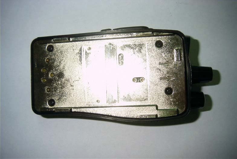
Click to zoom
Application Details
- Equipment Class
- TNF - Licensed Non-Broadcast Transmitter Held to Face
- Date of Grant
- Nov 12, 2003
- Application Purpose
- Original Equipment
- Date of Application
- Nov 12, 2003
- Equipment Note
- Portable radio
- Frequency Range
- 440.00000000 - 470.00000000
- Company
- Midland Radio Corporation
- Country
- United States
Documents & Files
Document Text
Text extracted from the exhibit documents filed with the FCC. Open a document above to read the original.
Users Manual
1 SP-220, 230, 240,250 series Synthesized Scanning Radio FCC RF EXPOSURE COMPLIANCE REQUIREMENTS FOR OCCUPATIONAL USE ONLY The Federal Communications Commission (FCC), with its action in General Docket 93-62, November 7, 1997, has adopted a safety standard for human exposure to Radio Frequency (RF) electromagnetic energy emitted by FCC regulated equipment. Maxon subscribes to the same safety standard for the use of its products. Proper operation of this radio will result in user exposure far below the Occupational Safety and Health Act (OSHA) and Federal Communications Commission limits. DO NOT transmit for more than 50% of total radio use time (50% duty cycle). Transmitting more than 50% of the time can cause FCC RF exposure compliance requirements to be exceeded. This radio is NOT approved for use by the general population in an uncontrolled environment. This radio is restricted to occupational use, work related operations only where radio operator must have the knowledge to control the user’s exposure conditions for satisfying the higher exposure limit allowed for occupational use. When transmitting, hold the radio in a vertical position with its microphone 2 inches (5 cm) away from your mouth. The radio is transmitting when the red LED on the front of the radio is illuminated. You can cause the radio to transmit by pressing the PTT bar on the radio. These are required operating configurations for meeting FCC RF exposure compliance. Failure to observe these restrictions mean violation. Operating Instructions About Your SP-220, 230, 240, 250 series Radio Midland Radio Corporations Maxon brand SP-220, 230, 240, 250 series radio feature a 4 or 16 channel rotary switch. Operation and functions for the SP-220, 230, 240, 250 series are described in this manual. We urge you to thoroughly read this manual before operating the radio. Application of some of the functions described in this manual is determined by the system you use. Your Dealer will program your radio so that you have the greatest number of functions possible relative to your needs. Should you have questions regarding the operation of the radio please consult your Dealer. 2 Table of Contents Safety Information.................................................................. Unpacking Information.......................................................... SP-220, 230, 240, 250 Series Features................................... Description of Radio Components......................................... Antenna Installation............................................................... Installing and Removing the Battery Pack............................... Attaching and Removing the Belt Clip.................................... Battery Charging and Care..................................................... SP-220, 230, 240, 250 Series Operation................................. Power On-Volume.................................................. Channel Select Transmit.................................................................. Receive................................................................... Power Off.............................................................. Status Indicators and Audible Alert Tones............................. Scan Modes......................................................................... Normal Channel Scan............................................ Priority Channel Scan............................................. Other Scanning Features....................................................... Scan Channel Delete.............................................. CTCSS/DCS Scanning............................................ Normal Scan TX..................................................... Priority Scan TX..................................................... Priority Only TX..................................................... Receive Only Scan................................................. Licensing and Service Information........................................ Software Copyrights............................................................. Maintenance........................................................................ Warranty Statement................................................................. 1 Safety Information The Federal Communications Commission (FCC), with its action in General Docket 93-62, November 7, 1997, has adopted a safety standard for human exposure to Radio Frequency (RF) electromagnetic energy emitted by FCC regulated equipment. Maxon subscribes to the same safety standard for the use of its products. Proper operation of this radio will result in user exposure far below the Occupational Safety and Health Act (OSHA) and Federal Communications Commission limits. WARNING - DO NOT hold the radio in such a manner that the antenna is next to, or touching, exposed parts of the body, especially the face or eyes, while transmitting. WARNING - DO NOT allow children to operate transmitter - equipped radio equipment. CAUTION - DO NOT operate the radio near unshielded electrical blasting caps or in an explosive atmosphere unless it is a type especially designed and qualified for such use. CAUTION - DO NOT press and hold the transmit switch (P-T-T) when not actually wishing to transmit. NOTE: This radio operates in FCC regulated frequency bands. All radios must be licensed by the FCC before use. Because this radio contains a transmitter, Federal law prohibits unauthorized use or adjustments of this radio. 3 Unpacking Information Remove and carefully inspect the contents of your package(s) for the following items: Radio Battery Pack Battery Charger Battery Charger Power Supply Antenna Spring Belt Clip Operating Instructions If any items are missing, please contact your Dealer . SP-220, 230, 240, 250 Series Features · Wideband frequency separation · 1 or 5 W programmable output power · Programmable 12.5/25 kHz channel spacing · Channel scan · Priority channel scan · CTCSS/DCS tone…
Text truncated - open the document above for the full version.
External Photos
Midland Radio Corporation FCC ID: MMASP200U2 APPENDIX C - EUT PHOTOGRAPHS Chassis - Front View Chassis – Back View Midland Radio Corporation FCC ID: MMASP200U2 Chassis – Right Side View Chassis – Left Side View Midland Radio Corporation FCC ID: MMASP200U2 Chassis – Top View Chassis with Antenna – Front View Midland Radio Corporation FCC ID: MMASP200U2 Chassis with Antenna – Back View Chassis with Antenna – Top View Midland Radio Corporation FCC ID: MMASP200U2 Antenna View
ID Label/Location Info
APPENDIX A - FCC ID LABELING AND LOCATION Proposed FCC ID Labeling Proposed FCC ID Location Rear Side of EUT / Proposed Label Location FCC ID: MMASP200U2
Internal Photos
Midland Radio Corporation FCC ID: MMASP200U2 EUT – Board and Housing View EUT – Board Component View Midland Radio Corporation FCC ID: MMASP200U2 EUT – RF Board and Housing View EUT – RF Board Component View
Operational Description
TECHNICAL SPECIFICATION FOR SP-220-250 PORTABLE RADIO ISSUE 1.0 LMR DIVISION MAXON KOREA MAXON DIVISION SIGNATURE DATE MARKETING MAI MARKETING MEL MAXKOR Introduction The SP-220-250 is a small, lightweight handportable for applications where small size is the primary requirement. The SP-220-250 used a BCD Encoder SW and the current RF circuit of SP-210 and applied a new LMR ASIC in stead of Analog circuit, which is capable of Automatic Adjustment by a PC and test equipments. Both the VHF and UHF models are controlled by PLL / microprocessor Content ● Unit ● ANT ● Metal-Hydride Battery Pack(7.5V/1350mAh) ● Drop in Charger ● Adaptor Features ● On/Off & Volume Switch ● PTT Switch ● Monitor Switch ● External One Jack ● 4/16 channels /with CTCSS and DCS ● 12.5 KHz /20 KHz/ 25KHz Programmable ● 1/5 Watts Switchable Main Function ● Wideband ● Standard/Non-Standard CTCSS signaling ● Transmit Time-Out-timer/TX Inhibit ● Low Battery Indication ● Memory Protect ● Battery save Circuitry ● 4/16 Channels Wideband This software is made to work and control the wide band receiver/transmitter board. Marked Idle Enable If this function is enabled, the unit will transmit provided that the correct programmed CTCSS tone has been decoded. This function is essential for repeater operation. Standard/Non-Standard CTCSS When programming a channel with CTCSS, any frequency from 55 to 250 Hz can be selected in 0.1 Hz increments. The radio will be capable of encoding and decoding two non-standard CTCSS tones. Transmit Time-Out-Timer (TOT)/TX Inhibit The time-out-timer is system programmable for 10 seconds to 990 seconds, in 10 second increments and cans also be selected as disabled. The default value is 10 seconds. The addition to this feature is a programmable lock-out-timer that inhibits the radio transmitter for a specified time after the time-out-timer expires. When the time-out-timer function is enabled,and the TX inhibit function is disabled, the radio will transmit after the time-out-timer has expired and the PTT button is released and again depressed. With the TOT and TX enabled, the radio will not transmit after the time-out-timer has expired, even if the PTT is released and depressed again. Transmission will not be allowed until the TX inhibit time has expired. Tx inhibit time is system programmable from 5 to 60 seconds in 5 second increments. The default value for the TX inhibit is 5 seconds. The radio will beep one time, 5 seconds before the TOT time expires. This will indicate to the user that the transmitter is about to be locked out.. If the PTT is released and depressed again anytime before the TOT has expired, the TOT time will be reset. If the beep tone enable /disable is set to disable , the one beep will not be issued. The radio will beep 4 times when the TOT time expires. After the TX inhibit time passes, the radio will beep one final time. VCO Lock Time The micro will allow more lock time for the VCO before the indication of out-of-lock beep. Low Battery Indication Low Battery Indication will be changed so that it does not inhibit RX and will allow one transmission after low cell is indicated. Low cell will not be indicated during transmit mode. If the battery goes below sepecified limits during the TX mode, low cell will be indicated immediately after releasing the PTT button. After the low cell indication is issued, the transmitter can only be used one time. When the PTT is pushed again and then released, the transmitter is locked out unit the unit is powered down and then powered back up. Memory Protect The software is such that if the radio is inadvertently put into program mode it will not lose the contents of the EEPROM memory. Date will only move in and out of the memory when the program mer is attached. External Option Detect An input to the microprocessor will be available that will indicate to the microprocessor that the external option has been selected. This input should be connected to the external option connector. External option should be selected for each channel. If a channel is selected during programming for external option, this input should be active when the channel is selected during opteration of the unit. THEORY OF OPERATION The VHF and UHF handheld radios are comprised of a RF PCB and a Digital PCB. The RF PCB containts the transmitter, receiver circiuts and the Digital PCB, control circuits respectively. The control circuits contain the micro controller, Asic(Audio sigmal precessor) and associated digital circuits. DIGITAL CIRCUIT ASIC is comprised of Analog signal path, SAT signal path, miscellaneous signals and controller as follows Analog signal path A1 : is a BUFFER AMP to generate discriminator audio from Pin9 to ASW1. And its gain 1 A2 : amplifies analog signal which was received from IN2(Mic input terminal) by 10dB. And then output signal goes ASW1. ASW1 : is 2 way switch. It generates one of analog signals which was applied from A1 and A2. The control signal should be controlled by 1 bit signal. Default value is <0 and A1 is selected INTRIM : compensates the deviation for the input analog signal sensitivity. The control range of the signal is +3.5/-4dB and is controlled by 16 steps. And the control signal is handled by 4 bit signal. Default value is 1000 and gain is 0dB. HPF : was composed of the 8th order or more and the cut-off frequency is 300Hz. As for the attenuation characteristic of filter, the signal diggerence must at least over 30dB at the cut-off frequency 300Hz and the first 250Hz of attenuation bandwith. ASW2 : is 4 way switch. It receives analog signals from HPF and its output goes one of De-Emphasys, RXVOL or AMP(with 6dB/oct Pre-Emphasys), AMP(without Pre-Emphasys)by the control instruction. The control signal must be controlled by 2 bit signal. Default value is <00 and De-Emphasys is selected. DEMPHA : has a characteristic of +6dB/oct De-Emphasys. The gain for 1KHz Analog Signal which is appllied from ASW2 is 1. PREMPHA : has a characterist…
Text truncated - open the document above for the full version.
Operational Description
- - Revision History : COMMENTS ATTACHED TEST DATA Production Specification DIVISION : TWR R&D MODEL CODE : 7763 / 7765 MODEL NAME : SP-230/250/UHF STANDARD SPEC : TIA/EIA 603 DESCRIPTION : U/V PLL SYNTHESIZER REV NO. ECO NO DATE WRITTEN REVIEWED APPROVED 0 N/A 2003.08.03 Y.K.KIM WRITTEN BY : REVIEWED : APPROVED : PAGE : MSA-402-04-01B - - ELECTRICAL PERFORMANCE TEST(RX) MODEL : SP230/250 PAGE 2 OF 6 STANDARD SPEC : TIA/EIA603 DESTINATION :WORLD-WIDE TEST DATE : 2003 . 8 . 3 . SPECIFICATION FREQ NO TEST ITEM Normal Limit UNIT CHCHCH 1 SENSE 12 DB SINAD 120 -118(V) -117(U) DBM SQ.OPEN 12 614 (SINAD) dB PWR SAVING MAX16 (SINAD) dB 2 SQUELCH SQ (HYS) 0 - 6 DB SINAD N - BAND 3.5 KHz MIN 3 MOD. ACCEPTANCE B.W S - BAND 7.0 KHz MIN KHz STAND-BY 75 80 4 STAND-BY CURRENT PWR SAVING (100/400) 42 50 mA 0.30KHz + 12.5 + 2.5 0.6 KHz + 6.5 - 3.5 1 KHz 0 2 KHz - 4.0 - 14.0 3 KHz - 7.5 - 17.5 5 KHz LESS THEN - 12.0 5 AUDIO FREQUENCY RESPONSE 6 KHz LESS THEN - 13.5 dB N BAND 34 40(CTITT) 6 HUM / NOISE S BAND 40 dB 7 AUDIO DISTORTION 2 5 8 AUDIO OUTPUT (AT 10 THD) 8 ohm LOAD 2.2 MIN 1.6 RMS V - - ELECTRICAL PERFORMANCE TEST(RX) MODEL : SP-230/250 PAGE 3 OF 6 STANDARD SPEC : EIA/TIA603 DESTINATION :WORLD-WIDE TEST DATE : 2003 . 8. 3 . SPECIFICATION FREQ NO TEST ITEM Normal Limit UNIT CHCHCH +12.5K N-BAND -12.5K 65 50 +25K 10 ADJACENT CHANNEL SELECTIVITY S-BAND -25K 75 60 dB fc - 0.91 (U) fc + 0.91 (V) 60 11 SPURIOUS RESPONSE ATT. fc - 22.55 (U) fc + 22.55 (V) 70 60 dB 12 IMAGE REJECTION fc - 90.2 (U) fc + 90.2 (V) 68 60 dB +25/50K +50/100K -25/50K 13 INTER MODLATION DISTORTION (3 S.S.G) -50/100K 60 dB 14 CONDUCTED RX SPRIOUS - 53 dBm TEST CONDITION 1. STD. Supply Voltage : 7.5 Vdc At Batt Terminal 2. Normal Temperature : 255/EXTREME -30 - +60 3. STD. Audio Frequency : 1 KHz 4. STD. Deviation : N-BAND : 1.5 KHz S-BAND : 3.0 KHz 5. Main Signal Input Level : -47dBm 6. ANT. Impedance : 50 ohm 7. Carrier Frequency : 8. REF. Audio Output : 1V rms 9. Audio Output Load : 8 ohm 10.CH Spacing : N-BAND : 12.5 KHz S-BAND : 25 KHz - - ELECTRICAL PERFORMANCE TEST(TX) MODEL : SP-230/250 PAGE 4 OF 6 STANDARD SPEC : TIA/EIA603 DESTINATION : WORLD-WIDE TEST DATE : 2003 . 8 . 3 . SPECIFICATION FREQ NO TEST ITEM Normal Limit UNIT CHCHCH HIGH 5.0 (A)4 - 6 1 POWER OUTPUT LOW 1 0.8 - 1.5 + 10 + 2 dB - 10 - 3 dB APC MAX. 2 POWER OUTPUT APC MIN. Watt ROOM TEMP 3 FREQUENCY ERROR -10 750 (U) 500 (V) Hz 4 MAX. CURRENT (ANT/DUMI LOAD) 7.5V DC 2.2 2.5 A 2'ND 3'ND 5 CONDUCTED SPURIOUS EMISSION OTHER 60 dBC AUDIO at 1KHz (W/TONE) 2.5 N-BAND TONE 0.25 0.5 (USA) AUDIO at 1KHz (W/TONE) 5.0 6 PEAK FM DEVIATION (DCS : N/A) S-BAND TONE 0.5 1.0 (USA) KHz N-BAND 1.5 KHz 2 5 7 AUDIO DISTORTION S-BAND 3 KHz 2 5 N-BAND 1.5 KHz 40 34 40(CTITT) 8 HUM / NOISE S-BAND 3 KHz 45 40 dB - - ELECTRICAL PERFORMANCE TEST(TX) MODEL : SP-230/250 PAGE 5 OF 6 STANDARD SPEC : TIA/EIA DESTINATION : WORLD-WIDE TEST DATE : 2003 . 8 . 3 SPECIFICATION FREQ NO TEST ITEM Normal Limit UNIT CHCHCH 0.30 KHz (A) - 9.5 - 17.9 0.6 KHz - 3.5 - 7.5 1 KHz 0 2 KHz + 3.0 + 7.0 2.55 KHz(N) + 4.0 + 10.5 3 KHz(S) + 4.0 + 10.5 9 AUDIO RESPONSE 5 KHz dB 10 MIC SENSITITY 20 (A) 10-35 N-BAND 65 60 11 ADJACENT CHANNEL POWER S-BAND 75 70 dB 12 LOW BATTERY VOLTAGE 5.6 Vdc TEST CONDITION 1. STD. Supply Voltage : 7.5 Vdc 2. Normal Temperature :2510 /EXTREME -30 - +60 3. STD. Audio Frequency : 1 KHz 4. STD. Deviation : N-BAND : 1.5 KHz S-BAND : 3 KHz 5. Main Signal Input Level : -47dBm 6. ANT. Impedance : 50 ohm 7. Carrier Frequency : 8. REF. Audio Output : 1V rms 9. Audio Output Load : 8 ohm(Ext) 10. CH. Spacing : N-BAND : 12.5 KHz S-BAND : 25 KHz - - EXTREM CONDITIONS MODEL : SP-230/250 PAGE 6 OF 6 STANDARD SPEC : TIA/EIA DESTINATION : WORLD-WIDE TEST DATE : 2003 . 8 . 3 ITEMS Limit Freq -30 -20 -10 0 +10 +25 (REF) +50 +60 Remark F1 F2 SENTIVITY (12dB SINAD) (dBm) -116 F3 F1 F2 MAX AUDIO OUTOUT (Vrms) 1.5 F3 F1 F2 AUDIO DISTORTION (%) 10 F3 F1 F2 SQ(Audio on) (SINAD) 618 db F3 F1 F2 POWER (W) +2.0 -3.0 DB F3 F1 F2 CURRENT (A) Max 2.5 F3 F1 F2 FREQ.ERROR (ppm) +/-5 F3 F1 F2 PEAK DEV. (KHz) 2.5/5K F3 F1 F2 SPURIOUS & HARMONICS (dBc) -60dbc F3 REMARK THE UNIT UNDER TEST WAS IN A TEMPERATURE CHAMBER - -
Operational Description
- - TECHNICAL SPECIFICATION FOR SP-230/250 LOW COST 5 WATT HANDPORTABLE ISSUE 1.1 LAND MOBILE RADIO R&D TEAM MAXON KOREA SIGN OFF MAXON DIVISION SIGNATURE DATE MARKETING MAI MARKETING MEL MAXKOR - - SP-230/250 TECHNICAL SPECIFICATION TRANCEIVER NOMINAL PERFORMANCE MODEL: SP-230/250 U2 EQUIPMENT TYPE: Handportable PERFORMANCE SPECIFICATIONS: ETS 300-086 TIA/EIA-603 BAND: UHF/VHF CHANNEL SPACINGS: 12.5KHz,20KHz 25KHz PROGRAMMBLE RF OUTPUT POWER: 5 / 1 WATT MODULATION TYPE: F3E AUDIO POWER: 500mW ( EXT WITH 16 OHM) 1W ( INT WITH 4 OHM) INTERMEDIATE FREQUENCY: 45.1MHz 455KHz NO OF CHANNELS: 4/16 Channel BCD Encoder SW FREQUENCY SOURCE: SYNTHESIZER OPERATION RATING: INTERMITTENT 90 : 5 : 5 (STBY:RX:TX) POWER SUPPLY: NIMH 7.5 VDC NOMINAL EXTREME +/- 10% VDC EXTREME TEMPERATURE RANGE: STORAGE 80 MAX -40 MIN.(EXTREME) OPERATING 25+/-10 NOM(ROOM TEMP) 60 MAX -30 MIN. CURRENT OFF 150uA STANDBY(MUTED) BAT SAVE ON( 100mS, 400mS) 55mA BAT SAVE OFF 80mA UNMUTED 100% MAX AF POW 400mA TRANSMIT 5 WATT RF POW 2.4 A SWITCHING RANGE TX AND RX (WITHOUT RE-TUNING) RX TX VHF V1 138.000-162.000MHz 138.000-162.000MHz V2 148.000-174.000 148.000-174.000 UHF U2 440.000-470.000 440.000-470.000 U1 400.000-430.000 400.000-430.000 U5 420.000-450.000 420.000-450.000 U3 470.000-490.000 470.000-490.000 U4 490.000-512.000 490.000-512.000 BATTERY LIFE (MINIMUM) METHOD AS TIA/EIA-603 FEB 1993 Power Save : 100mS off / 400mS on 1350mA POWER SAVE ON 8 Hrs - - PHYSICAL PARAMETERS TBD TRAMSMITTER TEST METHOD IS TIA/EIA-603 FEB 1993 1 CARRIER POWER NOM. MAX. MIN 5.0W 6.0 4.5 1.0W 1.4 0.7 2 SUSTAINED TRANSMISSION METHOD(TX POWER VS TIME) NOMINAL CONDITIONS 5 10 30 SEC 90% >85% >80% POWER 3 FREQUENCY ERROR 0.5KHz NOMINAL CON. VHF 0.75KHz NOMINAL CON. UHF 5PPM EXTREME CON. VHF 3PPM EXTREME CON. UHF 4 AUDIO FREQUENCY DEV WITHOUT SUB AUDIO TONE MODULATION: CHANNEL SPACING: (NOM/EXTREME CONDITIONS) NOM. PEAK MIN. 25KHz 3 5.0 3.8 12.5KHz 1.5 2.5 1.8 WITH SUB AUDIO TONE MODULATION 10% PEAK DEVIATION CHANNEL SPACING: EXTREME CONDITIONS 25KHz 5.0 PEAK 12.5KHz 2.5 PEAK 5 AUDIO CHARACTERISTIC: MEATHOD AS TIA/EIA-603 MODE TYPE F3 WITHIN +1/-3dB of 6dB OCT. 300Hz to 2.55KHz for 12.5KHz C.S 300Hz to 3.0 KHz for 25KHz C.S 6 ADJACENT CHANNEL POWER 25KHz 70 dBc nominal conditions 65 dBc extreme conditions 12.5KHz 60 dBc nominal condition 55 dBc extreme codition 7 TX SPURIOUS EMISSION(CONDUCTED) BELOW 1 GHz -36 dBm nominal BELOW 4 GHz -30 dBm nominal 8 MODULATION SENSITIVITY At ACCESSORY/MIC CONNECTOR 15mV >20mV>35mV 60% PEAK DEV 9 TRANSMITTER AUDIO DISTORTION (WITHOUT CTCSS) 1KHz 5% 10% extreme condition - - 10 HUM & NOISE(Residual Modulation) Method as FTZ 17 TR 2049 July 1988 12.5kHz C.S. >40dB (with PSOPH) 25kHz C.S. >40dB (with no PSOPH) 11 Modulation Symmetry <10% Peak Dev Method(Peak Positive-Peak Negative) (@ 1KHz input for nominal dev + 20dB) 12 Load Stability No osc at >=10:1 VSWR all phase angles and suitable antenna No Destory at >=20:1 All phase angle 13 Peak Deviation Range Adjustment (@Nominal/Extreme Conditions) Channel Spacing: (@ 1KHz, Nom. Dev + 20dB) Min. Max. 25KHz >3.5 <6.0 20KHz >2.8 <5.0 12.5KHz >1.5 <4.0 TX TONE MODULATION CHARACTERISTICS SUB AUDIO TONES-CTCSS 1 Tone Range 67 TO 250Hz @ 0.3% Accuracy 2 Tone Standard TIA/EIA-603 3 Non-Standard Tones 50-260Hz @ 0.3% Accuracy 4 Nominal Tone Deviation 15% (10%-20%) Peak System Deviation USA 10% ( 8%-15%) Peak System Deviation UK 5 Deviation Range Adjustment 0% Min. Peak Dev 20% Max. Peak Dev Method(Using internal control @ nominal conditions) 6 Tone Deviation Variation vs. Tone Freq. and across Switch Range: <10% Peak Dev(@ 10% Peak system dev) Method(Tone Freq. vs. Deviation) 7 Tone Distortion 5% THD Method(@ 10% Peak system DEVITION) 8 Tx Audio Rejection >25dB Method (radio of Peak Dev at 300Hz) and Peak Dev at highest) (Standsrd tone frequency) 9 Response Time <10mS (Peak level after Tx on and within 1%accuracy) Method (time to generate tone to 90%) 10 Hum & Noise >35 WITH PSOPH Method (using any standard CTCSS tone) @10% Peak deviation (Using300Hz HPF nad 3KHz LPF) SUB AUDIO TONES-DCS 1 Tone Standard Normal and inverted 2 Tone Deviation 15% +/-5% Peak system deviation for MAI 10% +/-3% Peak system deviation for MEL 3. Deviation Range Adjustment 0% Min. Peak Dev 25% Max. Peak Dev Method using internal control(@ nominal conditions) 4 Deviation Variation vs.DCS Code and Carrier Freq: 5% Method(and DCS Code vs.deviation over switching - - SUB AUDIO TONES-DEVIATION COMPARISON 1 Deviation Difference <10% Peak Dev Method(deviation with CTCSS minus deviation with DCS Code 346 @ single channel with no adjustment) (@ Nominal and extreme conditions) RECEIVER Performance without Sub Audio Modulation 1 Sensitivity 12dB Sinad UHF: <-117dBm, VHF: <-118dBm (@ Nominal conditions across switching range) 12dB Sinad UHF: <-115dBm, VHF: <-116dBm (@ Extreme conditions across switching range) 2 Amplitude Characteristic <3dB 3 Adjacent Channel Selectivity 25KHz Channel Spacing >60dB (@Nominal conditions) >55dB (@Extreme conditions) 12.5KHz Channel Spacing >50dB (@Nomial conditions) >45dB (@Extreme conditions) 4 Spurious Response Rejection 70dB (100KHz -4GHz) (@NOMINAL CONDITIONS) (ACROSS SWITCHING RANGE) Image Response >60dB 1/2 IF Response >60dB Others >60dB 5 Intermodulation Response Rejection 25K/50KHz >60dB 50K/100KHz >60dB 6 Rx Spurious Emissions(Conducted) (@ Nominal conditions) 9kHz - 1GHz < -57dBm 1GHz -4GHz < -47dBm 7 Rx Spurious Emissions(Radiated) (@Nominal conditions) 9kHz - 1GHz < -57dBm 1GHz -12.75GHz < -47dBm 8 AF Power 550mW Maximum 10% Dist (EXT)At 8 Ohm) 1.1W (INT) At 4 Ohm Method (at < 10% THD Level) 9 Volume Control Adjustment Range < 10mW Min > 600mW Max. (8 OHM EXT ) Method (Lowest and Highest) (Volume control Positions) 10 AF Distortion Method as FTZ 17 TR 2049 1kHz <5% (@nominal conditions) <10% (@extreme conditions) 11 AF Frequency Response Method as TIA/EIA-603 MOD TYPE F3 Within +1/-3 dB of Limit WRT 1KHz (@300Hz to 3KHz for 20,25KHz Cham. Spacing) 12 Rx Hum & Noise Metho…
Text truncated - open the document above for the full version.
Parts List/Tune Up Info
MAINTENANCE AND REPAIR GENERAL UHF The UHF hand portable radio covers the UHF band from 400 to 500 MHz. The radio have been factory aligned for operation within frequency band. Any repair or adjustment should only be made by or under the supervision of a qualified radio service technician. REMOVING AND REPLACING When removing or fitting, use the Exploded View and Parts List in conjunction with the following procedures: Removing And Replacing Battery To remove the battery 1. Hold the radio chassis in one hand, press and hold the battery release catch on the top side. 2. Using the other hand, slide the battery toward the bottom side and off the the battery guide rail. To replace the battery 1. With the slides of the battery positioned in line with the radio battery rail guides, slide the battery into position untill a click is heard. ALIGNMENT PROCEDURE The SP230/250 U2 Receiver is designed for broad band covering UHF(440-470MHz) and should require no special alignment, unless repairs are performed on the receiver portion. The only alignment normally required is to squelch circuit, Apply a signal that produes 10dB SINAD, reduce the input to -130dBm, close the squelch control(RV2,RV4) until the receiver mutes. Increase the signal to 10dB SINAD reading reference level and adjust RV2 or RV4 until the squelch opens. In high noise environment, some users may prefer to have the squelch opening set somewhat tighter, e.g.:12 to 14dB SINAD. Should repairs be required, the following procedures should be applied: VCO 1. Set the unit to the lowest transmitter frequency, 440MHz(UHF), 138MHz(VHF) and adjust the VCO L203 to 2.5V and 1.0V respectively. 2. Set the unit to the highest transmitter frequency, 470MHz(UHF), 162MHz(VHF) and check that the VCO voltage is below 11 volts. 3. Set the unit to the lowest receiver frequency, 440MHz(UHF), and adjust the VCO C208 to 1.5V. 4. Set the unit to the highest receiver frequency 470MHz(UHF), 162(VHF) and check that the VCO voltage is below 11 volts. * Note : use TP1 to measure the voltage. Transmitter Connect the unit to a Service Monitor with the power meter setting to the 5 W scale (or autorange) TCXO Set the channel selector to the mid-range frequency 455 MHz, adjust CT1, for a reading of 445 MHz +/- 200Hz. For the VHF data radio, adjust the CT1 and set the frequency within the required range. APC 1. Adjust RV1 for fixing up High Power(5W) 2. Adjust RV3 for fixing up Low Power(1W) COMPOMENT REPLACEMENT Surface Mount Components Surface mount components should always be replaced using a temperature controlled soldering system. The soldering tools may be ether a temperature controlled soldering iron or a temperature controlled hot-air soldering station. A hot-air system is recommended for the removal of components on these boards. With either soldering system, a temperature of 700 F(371 C) should be maintained. The following procedures outline the removal and replacement of surface mount components. If a hot-air soldering system is employed. See the manufacture's operating instructions for detailed information on the use of your system. * CAUSION : Avoid applying heat to the body of any surface mount component using standard soldering methods. Heat should be applied only to the metailzed terminals of the components. Hot-air systems do not damage the components since the heat is quickly and evenly distributed to the external surface of the component. * CAUSION : The CMOS Integrated Circuit devices used in this equipment can be destroyed by static discharges. Before handling one of these devices, service technicians should discharge themselves by touching the case of a bench test instrument that has a 3-prong power cord connected to an outlet with a know good earth ground. When soldering or desoldering a CMOS device, the soldering equipment should have a known good earth ground. Surface Mount Removal 1. Grip the component with tweezers or small needle nose plies. 2. Alternately heat the metalized terminal ends of the surface mount component with the soldering iron. If a hot- air system is used, direct the heat to the terminals of the component. Use extreme care with the soldering equipment to prevent damage to the printed circuit board (PCB) and the surrounding components. 3. When the soldering on all terminals is liquefied, gently remove the component. Excessive force may cause the PCB pads to separate from the board if all solder is not completely liquefied. 4. It may be necessary to remove excess silder using a vacuum de-soldering tool or Solder wick. Again, us great care when de-soldering or soldering on the printed circuit board. It may also be necessary to remove the epoxy adhesive that was under the surface mount component and any flux on the printed circuit board. Surface Mount Component Replacement 1. "Tin" one terminal end of the new component and the corresponding pad of one the PCB. Use as little solder as possible. 2. Please the component on the PCB pads, observing proper polarity for capacitors, diodes, transistors, etc. 3. Simultaneously touch the " tinned" terminal end and the " tinned" pad with the soldering Iron. Slightly press the components down on the board as the solder liquefies. Solder all terminals, allowing the component time too cool between each application of heat. Do not apply heat for an excessive length of time and do not use excessive solder. With a hot-air system, apply hot air until all "tinned" areas are melted and the component is seated in place. It may be necessary to slightly press the component down on the board. Touch-up the soldered connections with a standard soldering iron if needed. Do not use excessive solder. * CAUSION: Some chemicals may damage the internal and external plastic parts of the radio. 4. Allow the component and the board to cool and then remove all flux from the area using alcohol or another approved flux remover. Surface Mounted Integrated Circuit Replacement Soldering and de-soldering techniques of th…
Text truncated - open the document above for the full version.
Parts List/Tune Up Info
DEVELOPMENT : FINAL P A R T S L I S T # RIR610B DESIGN : UNFINISHED =================== TECHNIQUE : NO DATA Rev.: 004 S/W VERSION : UNDEFINED MODEL CODE : 7763 SP-230 UHF PORTABLE, 5W, 4CH ( ) 3/09/24 07:37:46 1 -------------------------------------------------------------------------------- ---------------------------------------------------------------------- SEQ LEVEL PART-NO. NAME & DESCRIPTION Q'TY UT G KON OPT REFERENCE-NO ECO-DATE ECO-NO. -------------------------------------------------------------------------------- ---------------------------------------------------------------------- 1 2 577-63B-A BATTERY ASS'Y 1.000 EA A 3/06/19 A CS-HJLEE 3 508-753-A TERMINAL PCB ASS'Y SP-200 1.000 EA B SUB 3/06/19 4 406-766-A P.C.B BATTERY 38.2 X89.3 X1MI FLEX1/0 1.000 EA B SUB 2/08/23 C AT02-PAT 4 752-958 TERMINAL BSP T1.2 GOLD-PLATIN 2.000 EA B SUB 99/01/14 C B99-0114 4 753-037 TERMINAL BSBM GOLD-PLATING 4.000 EA B SUB 99/01/14 C B99-0114 3 71A-005 BATT PACK PC LEXAN 141-70456 BLK…
Text truncated - open the document above for the full version.
Contact Information
Applicant
Butch Rittmann(Director of Operations)
Test Firm
Bay Area Compliance LaboratoryJohn Chan
Technical Specifications
| # | Rule Parts | Frequency Range | Power Output | Emission | Tolerance |
|---|---|---|---|---|---|
| 2 | 9 | 440 MHz - 470 MHz | 5 W | 6K00F3E | 2.5 ppm |
Other Applications from Midland Radio Corporation

MMAMXMC95
Jun 10, 2026Wireless Bluetooth Microphone
Equipment Class
JAB - Part 15 Class B Digital Device
MMAMXT295
Jun 08, 2026GMRS Radio
Equipment Class
TNF - Licensed Non-Broadcast Transmitter Held to Face
MMACLIPTALK
Apr 27, 2026Transceiver
Equipment Class
DTS - Digital Transmission System
MMABR200S
Jan 13, 2026BUSINESS BAND TWO-WAY RADIO
Equipment Class
TNF - Licensed Non-Broadcast Transmitter Held to Face
MMAGXT67
Oct 29, 2023GMRS RADIO
Equipment Class
TNF - Licensed Non-Broadcast Transmitter Held to Face