MMASP200V2Portable Radio
Midland Radio Corporation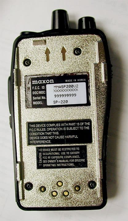
Click to zoom
Application Details
- Equipment Class
- TNB - Licensed Non-Broadcast Station Transmitter
- Date of Grant
- Feb 26, 2004
- Application Purpose
- Original Equipment
- Date of Application
- Dec 02, 2003
- Equipment Note
- Portable Radio
- Frequency Range
- 146.00000000 - 174.00000000
- Company
- Midland Radio Corporation
- Country
- United States
Documents & Files
Document Text
Text extracted from the exhibit documents filed with the FCC. Open a document above to read the original.
Users Manual
1 SP-220, 230, 240,250 series Synthesized Scanning Radio FCC RF EXPOSURE COMPLIANCE REQUIREMENTS FOR OCCUPATIONAL USE ONLY The Federal Communications Commission (FCC), with its action in General Docket 93-62, November 7, 1997, has adopted a safety standard for human exposure to Radio Frequency (RF) electromagnetic energy emitted by FCC regulated equipment. Maxon subscribes to the same safety standard for the use of its products. Proper operation of this radio will result in user exposure far below the Occupational Safety and Health Act (OSHA) and Federal Communications Commission limits. DO NOT transmit for more than 50% of total radio use time (50% duty cycle). Transmitting more than 50% of the time can cause FCC RF exposure compliance requirements to be exceeded. This radio is NOT approved for use by the general population in an uncontrolled environment. This radio is restricted to occupational use, work related operations only where radio operator must have the knowledge to control the user’s exposure conditions for satisfying the higher exposure limit allowed for occupational use. When transmitting, hold the radio in a vertical position with its microphone 2 inches (5 cm) away from your mouth. The radio is transmitting when the red LED on the front of the radio is illuminated. You can cause the radio to transmit by pressing the PTT bar on the radio. These are required operating configurations for meeting FCC RF exposure compliance. Failure to observe these restrictions mean violation. Operating Instructions About Your SP-220, 230, 240, 250 series Radio Midland Radio Corporations Maxon brand SP-220, 230, 240, 250 series radio feature a 4 or 16 channel rotary switch. Operation and functions for the SP-220, 230, 240, 250 series are described in this manual. We urge you to thoroughly read this manual before operating the radio. Application of some of the functions described in this manual is determined by the system you use. Your Dealer will program your radio so that you have the greatest number of functions possible relative to your needs. Should you have questions regarding the operation of the radio please consult your Dealer. 2 Table of Contents Safety Information.................................................................. Unpacking Information.......................................................... SP-220, 230, 240, 250 Series Features................................... Description of Radio Components......................................... Antenna Installation............................................................... Installing and Removing the Battery Pack............................... Attaching and Removing the Belt Clip.................................... Battery Charging and Care..................................................... SP-220, 230, 240, 250 Series Operation................................. Power On-Volume.................................................. Channel Select Transmit.................................................................. Receive................................................................... Power Off.............................................................. Status Indicators and Audible Alert Tones............................. Scan Modes......................................................................... Normal Channel Scan............................................ Priority Channel Scan............................................. Other Scanning Features....................................................... Scan Channel Delete.............................................. CTCSS/DCS Scanning............................................ Normal Scan TX..................................................... Priority Scan TX..................................................... Priority Only TX..................................................... Receive Only Scan................................................. Licensing and Service Information........................................ Software Copyrights............................................................. Maintenance........................................................................ Warranty Statement................................................................. 1 Safety Information The Federal Communications Commission (FCC), with its action in General Docket 79-144, March 13, 1985, has adopted a safety standard for human exposure to Radio Frequency (RF) electromagnetic energy emitted by FCC regulated equipment. Maxon subscribes to the same safety standard for the use of its products. Proper operation of this radio will result in user exposure far below the Occupational Safety and Health Act and Federal Communications Commission limits. WARNING - DO NOT hold the radio in such a manner that the antenna is next to, or touching, exposed parts of the body, especially the face or eyes, while transmitting. WARNING - DO NOT allow children to operate transmitter - equipped radio equipment. CAUTION - DO NOT operate the radio near unshielded electrical blasting caps or in an explosive atmosphere unless it is a type especially designed and qualified for such use. CAUTION - DO NOT press and hold the transmit switch (P-T-T) when not actually wishing to transmit. NOTE: This radio operates in FCC regulated frequency bands. All radios must be licensed by the FCC before use. Because this radio contains a transmitter, Federal law prohibits unauthorized use or adjustments of this radio. Unpacking Information 3 Remove and carefully inspect the contents of your package(s) for the following items: Radio Battery Pack Battery Charger Battery Charger Power Supply Antenna Spring Belt Clip Operating Instructions If any items are missing, please contact your Dealer . SP-220, 230, 240, 250 Series Features · Wideband frequency separation · 1 or 5 W programmable output power · Programmable 12.5/25 kHz channel spacing · Channel scan · Priority channel scan · CTCSS/DCS tone signali…
Text truncated - open the document above for the full version.
Cover Letter(s)
Instructions to Jennifer Please copy and paste and insert files Response to: FCC ID MMASP200V2 Applicant: Midland Radio Corporation Correspondence Reference Number: 26233 731 Confirmation Number: EA667298 1) Please provide liquid recipes. Liquid Recipe Constituents 150 MHz Body, constitution by weight 150 MHz Head - constitution, by weight Water 45.45 % 50 % Sucrose 52.48 % 46 % NaCl 1.62 % 3.55% HEC 0.2 % 0.2 % Bactericide 0.25 % 0.25 % 2) Please justify use of probe at 300 MHz. No calibration certification could be located. This was discussed with Mr. Tim Harrington. See attached letter. Our probe is calibrated at 150 MHz and at 450 MHz. EUT testing was done with 150 MHz liquid per Tim Harrington's instructions. System validation was done at 300 MHz using 300 MHz liquid, and using the 300 MHz antenna. The justification is that due to the low frequency, the behavior of the dielectric is predictable and the probe factor is predictable. The error variance is expected to be less than 15% and this EUT has adequate margin to absorb this increase fractional error. In C95.3-2002, page 62, the error is calculated not to exceed 10% for the range from 30 to 300 MHz. Letter: From: "hansm" <[email protected]> To: "Tim Harrington" <[email protected]> Sent: Wednesday, November 05, 2003 3:27 PM Subject: 150 MHz SAR testiing > Dear Mr. Tim Harrington > > I am reviewing a test plan with my technician Eric Yee whom you've recently > corresponded with and you stated that you have been accepting for 150 MHz > EUT's system validation using 300 MHz dipole, liquid and probe factor. May > we use 150 MHz liquid and probe factors with the 300 MHz antenna? That, in > my opinion, will result in better accuracy. I also believe that the IEC had > considered that approach as well. > We do not have current 300 MHz probe factors and if necessary, would you > allow a linear interpolation between 150 and 450 to derive 300 MHz probe > factors? We have two probes and the 300 MHz data is out of cal and on the > second probe we did not cal the 300 MHz. > As an alternative, I can do comparative probe measurements between the old > and the new probe to show equivalence between 150 and 450 MHz and thereby > validate by inference that the 300 MHz probe factors have remained > unchanged. I would prefer if you accept the interpolated data for this test > instead of the comparative measurements between the old and new probe. > Thank you for your consideration. > Comments? > > Best Regards > > > Hans Mellberg > Engineering Manager > BACL > 230 Commercial Street > Sunnyvale CA 94085 USA > 408-732-9162 x38 > 408-732-9164 fax 3) Please justify use of Agilent 85070A dielectric probe at 150 MHz. The dielectric probe is rated from 200 MHz to 20 GHz. This range is stated as nominal and can be extended above 20 GHz and below 200 MHz. In our case, the extension to 150 MHz is only 50 MHz from the stated nominal minimum. The probe's error is stated to reduce in value with increasing relative dielectric value. In our case, the relative dielectric values range from 45 to 67, well in the upper range of lower expected measurement error. See page 4, Accuracy, of Agilent 8570D Dielectric Probe Kit, Product Overview While using the software package by Agilent, the frequency spectrum swept is nulled and calibrated in air, de-ionized 18 Meg Ohm water, and a direct short. This also accounts for reduced error of measurement by extending the range of measurement for the probe. Agilen'ts software package, 85070A, allows the use of the 150 MHz range to be used with the 85070D probe kit. 4) Please provide conducted power versus time for at least 30 minute length. See attached file “conducted dBm vs 30 minutes.xls” 5) Please provide detail of antenna design. Include type and expected VSWR. See file “antenna spec.pdf” 6) Please provide a photo of the RF exposure warning label affixed to the device referring users of the exposure and referenced training information. See file “Maxon_SP-220.jpg” 7) The form 731 under technical specification shows FCC Rule Part 80 ONLY. The test report shows FCC Rule Part 80 and 90. Please clarify. The technical specification in form731 can only let us choose one standard. But the frequency ranges apply to both Part80 and Part90.
External Photos
APPENDIX C - EUT EXTERNAL PHOTOGRAPHS Chassis - Front View Chassis – Rear View Chassis – PTT Side View Chassis – Ear/Microphone Side View Chassis – Top View Antenna View Power Adapter View Battery View Charger View Earphone/Microphone View
ID Label/Location Info
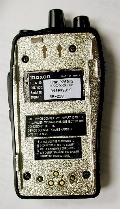
APPENDIX A - FCC ID LABELING AND LOCATION Proposed FCC ID Labeling Proposed FCC ID Location Rear Side of EUT / Proposed Label Location FCC ID: MMASP200V2
Internal Photos
APPENDIX C - EUT INTERNAL PHOTOGRAPHS EUT – Board and Housing View EUT – Board Component View EUT – RF Board and Housing View EUT – RF Board Component View
Operational Description
TECHNICAL SPECIFICATION FOR SP-220/240 PORTABLE RADIO ISSUE 1.0 LMR DIVISION MAXON KOREA Introduction The SP-230/250 is a small, lightweight handportable for applications where small size is the primary requirement. The SP-230/250 used a BCD Encoder SW and the current RF circuit of SP-210 and applied a new LMR ASIC in stead of Analog circuit, which is capable of Automatic Adjustment by a PC and test equipments. Both the VHF and UHF models are controlled by PLL / microprocessor Content ● Unit ● ANT ● Metal-Hydride Battery Pack(7.5V/1350mAh) ● Drop in Charger ● Adaptor MAXON DIVISION SIGNATURE DATE MARKETING MAI MARKETING MEL MAXKOR Features ● On/Off & Volume Switch ● PTT Switch ● Monitor Switch ● External One Jack ● 4/16 channels /with CTCSS and DCS ● 12.5 KHz /20 KHz/ 25KHz Programmable ● 1/5 Watts Switchable Main Function ● Wideband ● Standard/Non-Standard CTCSS signaling ● Transmit Time-Out-timer/TX Inhibit ● Low Battery Indication ● Memory Protect ● Battery save Circuitry ● 4/16 Channels Wideband This software is made to work and control the wide band receiver/transmitter board. Marked Idle Enable If this function is enabled, the unit will transmit provided that the correct programmed CTCSS tone has been decoded. This function is essential for repeater operation. Standard/Non-Standard CTCSS When programming a channel with CTCSS, any frequency from 55 to 250 Hz can be selected in 0.1 Hz increments. The radio will be capable of encoding and decoding two non-standard CTCSS tones. Transmit Time-Out-Timer (TOT)/TX Inhibit The time-out-timer is system programmable for 10 seconds to 990 seconds, in 10 second increments and cans also be selected as disabled. The default value is 10 seconds. The addition to this feature is a programmable lock-out-timer that inhibits the radio transmitter for a specified time after the time-out-timer expires. When the time-out-timer function is enabled,and the TX inhibit function is disabled, the radio will transmit after the time-out-timer has expired and the PTT button is released and again depressed. With the TOT and TX enabled, the radio will not transmit after the time-out-timer has expired, even if the PTT is released and depressed again. Transmission will not be allowed until the TX inhibit time has expired. Tx inhibit time is system programmable from 5 to 60 seconds in 5 second increments. The default value for the TX inhibit is 5 seconds. The radio will beep one time, 5 seconds before the TOT time expires. This will indicate to the user that the transmitter is about to be locked out.. If the PTT is released and depressed again anytime before the TOT has expired, the TOT time will be reset. If the beep tone enable /disable is set to disable , the one beep will not be issued. The radio will beep 4 times when the TOT time expires. After the TX inhibit time passes, the radio will beep one final time. VCO Lock Time The micro will allow more lock time for the VCO before the indication of out-of-lock beep. Low Battery Indication Low Battery Indication will be changed so that it does not inhibit RX and will allow one transmission after low cell is indicated. Low cell will not be indicated during transmit mode. If the battery goes below sepecified limits during the TX mode, low cell will be indicated immediately after releasing the PTT button. After the low cell indication is issued, the transmitter can only be used one time. When the PTT is pushed again and then released, the transmitter is locked out unit the unit is powered down and then powered back up. Memory Protect The software is such that if the radio is inadvertently put into program mode it will not lose the contents of the EEPROM memory. Date will only move in and out of the memory when the program mer is attached. External Option Detect An input to the microprocessor will be available that will indicate to the microprocessor that the external option has been selected. This input should be connected to the external option connector. External option should be selected for each channel. If a channel is selected during programming for external option, this input should be active when the channel is selected during opteration of the unit. THEORY OF OPERATION The VHF and UHF handheld radios are comprised of a RF PCB and a Digital PCB. The RF PCB containts the transmitter, receiver circiuts and the Digital PCB, control circuits respectively. The control circuits contain the micro controller, Asic(Audio sigmal precessor) and associated digital circuits. DIGITAL CIRCUIT ASIC is comprised of Analog signal path, SAT signal path, miscellaneous signals and controller as follows Analog signal path A1 : is a BUFFER AMP to generate discriminator audio from Pin9 to ASW1. And its gain 1 A2 : amplifies analog signal which was received from IN2(Mic input terminal) by 10dB. And then output signal goes ASW1. ASW1 : is 2 way switch. It generates one of analog signals which was applied from A1 and A2. The control signal should be controlled by 1 bit signal. Default value is <0>and A1 is selected INTRIM : compensates the deviation for the input analog signal sensitivity. The control range of the signal is +3.5/-4dB and is controlled by 16 steps. And the control signal is handled by 4 bit signal. Default value is < 1000> and gain is 0dB. HPF : was composed of the 8th order or more and the cut-off frequency is 300Hz. As for the attenuation characteristic of filter, the signal diggerence must at least over 30dB at the cut-off frequency 300Hz and the first 250Hz of attenuation bandwith. ASW2 : is 4 way switch. It receives analog signals from HPF and its output goes one of De-Emphasys, RXVOL or AMP(with 6dB/oct Pre-Emphasys), AMP(without Pre-Emphasys)by the control instruction. The control signal must be controlled by 2 bit signal. Default value is <00>and De-Emphasys is selected. DEMPHA : has a characteristic of +6dB/oct De-Emphasys. The gain for 1KHz Analog Signal which is appllied from ASW2 is 1. PREMPHA : has a characterist…
Text truncated - open the document above for the full version.
Parts List/Tune Up Info
PL7764.TXT DEVELOPMENT : FINAL P A R T S L I S T # RIR610B DESIGN : UNFINISHED =================== TECHNIQUE : NO DATA Rev.: 003 S/W VERSION : UNDEFINED MODEL CODE : 7764 SP-240 VHF PORTABLE, 5W, 16CH ( ) 3/09/24 12:08:24 1 ------------------------------------------------------------------------------------ ------------------------------------------------------------------ SEQ LEVEL PART-NO. NAME & DESCRIPTION Q'TY UT G KON OPT REFERENCE-NO ECO-DATE ECO-NO. ------------------------------------------------------------------------------------ ------------------------------------------------------------------ 1 2 532-58B-A BATTERY ASS'Y 1.000 EA A 3/09/04 A CS-HJLEE 3 099-303-6 THERMISTOR DISK 30K 15%:KC5D330L 1.000 EA B SUB TH1 3/04/01 3 249-065-8 DIODE SCHOTTKY ERB83-006 60V 2A 1.000 EA B SUB D1 3/04/01 3 420-517-0 BATTERY NI-MH VH1600AA 1.2V 1550MAH 6.000 EA B SUB 3/04/01 3 439-079-0 SW POLY LTP-300(BMB-1200) 1.000 EA B SUB SW801 3/04/01 3 508-753-A TERMINAL PCB ASS'Y SP-200 1.000 EA B SUB 3/04/01 4 406-766-A P.C.B BATTERY 38.2 X89.3 X1MI FLEX1/0 1.000 EA B SUB 2/08/23 C AT02-PAT 4 752-958 TERMINAL BSP T1.2 GOLD-PLATIN 2.000 EA B SUB 99/01/14 C B99-0114 4 753-037 TERMINAL BSBM GOLD-PLATING 4.000 EA B SUB 99/01/14 C B99-0114 3 71A-005 BATT PACK PC LEXAN 141-70456 BLK 1.000 EA B SUB 3/04/01 3 719-657-A COVER BATTERY LEXAN 141-70456 BLK 1.000 EA B SUB 3/04/01 3 752-808 CONTACT PLATE 18X3XT0.15 NI-PLATE 5.000 EA B SUB 3/04/01 3 752-821 CONTACT PALTE 74X3XT0.15 NI-PLATE(DPB-1190A) 1.000 EA B SUB 3/04/01 3 753-061 SPACER ABS94HB BLK 4.000 EA B SUB 3/04/01 3 826-395 KNOB LATCH(1050MA) LEXAN141-70456 BLK 1.000 EA B SUB 3/04/01 3 826-396 LATCH SUS T1.0 1.000 EA B SUB 3/04/01 3 826-492 KNOB SLIDE PC LEXAN141-704568 BLK 1.000 EA B SUB 3/04/01 3 881-656 SPRING(FOR LATCH) SUS 304 WPA &0.3 1.000 EA B SUB FOR LATCH 3/04/01 3 906-648 INSULATION PLATE 40X10XT1.0 FELT 2.000 EA B SUB 3/04/01 3 906-649 INSULATION PLATE 8X20XT0.25 INSU.PAP 2.000 EA B SUB 3/04/01 3 906-650 INSULATION PLATE 40X9XT0.25 INSUL.PAP 2.000 EA B SUB 3/04/01 3 906-857 DOUBLE TAPE 34X10XT0.16 3M 1.000 EA B SUB 3/04/01 3 906-858 DOUBLE TAPE 32X17XT0.16 3M 1.000 EA B SUB 3/04/01 3 906-939 DOUBLE TAPE 1.000 EA B SUB 3/04/01 3 95A-670-L LABEL BATTERY POLYESTER 49.5X25.5 1.000 Page 1 PL7762.TXT DEVELOPMENT : FINAL P A R T S L I S T # RIR610B DESIGN : UNFINISHED =================== TECHNIQUE : NO DATA Rev.: 003 S/W VERSION : UNDEFINED MODEL CODE : 7762 SP-220 VHF PORTABLE, 5W, 4CH ( ) 3/09/24 12:08:13 1 ------------------------------------------------------------------------------------ ------------------------------------------------------------------ SEQ LEVEL PART-NO. NAME & DESCRIPTION Q'TY UT G KON OPT REFERENCE-NO ECO-DATE ECO-NO. ------------------------------------------------------------------------------------ ------------------------------------------------------------------ 1 2 532-58B-A BATTERY ASS'Y 1.000 EA A 3/09/05 A CS-HJLEE 3 099-303-6 THERMISTOR DISK 30K 15%:KC5D330L 1.000 EA B SUB TH1 3/04/01 3 249-065-8 DIODE SCHOTTKY ERB83-006 60V 2A 1.000 EA B SUB D1 3/04/01 3 420-517-0 BATTERY NI-MH VH1600AA 1.2V 1550MAH 6.000 EA B SUB 3/04/01 3 439-079-0 SW POLY LTP-300(BMB-1200) 1.000 EA B SUB SW801 3/04/01 3 508-753-A TERMINAL PCB ASS'Y SP-200 1.000 EA B SUB 3/04/01 4 406-766-A P.C.B BATTERY 38.2 X89.3 X1MI FLEX1/0 1.000 EA B SUB 2/08/23 C AT02-PAT 4 752-958 TERMINAL BSP T1.2 GOLD-PLATIN 2.000 EA B SUB 99/01/14 C B99-0114 4 753-037 TERMINAL BSBM GOLD-PLATING 4.000 EA B SUB 99/01/14 C B99-0114 3 71A-005 BATT PACK PC LEXAN 141-70456 BLK 1.000 EA B SUB 3/04/01 3 719-657-A COVER BATTERY LEXAN 141-70456 BLK 1.000 EA B SUB 3/04/01 3 752-808 CONTACT PLATE 18X3XT0.15 NI-PLATE 5.000 EA B SUB 3/04/01 3 752-821 CONTACT PALTE 74X3XT0.15 NI-PLATE(DPB-1190A) 1.000 EA B SUB 3/04/01 3 753-061 SPACER ABS94HB BLK 4.000 EA B SUB 3/04/01 3 826-395 KNOB LATCH(1050MA) LEXAN141-70456 BLK 1.000 EA B SUB 3/04/01 3 826-396 LATCH SUS T1.0 1.000 EA B SUB 3/04/01 3 826-492 KNOB SLIDE PC LEXAN141-704568 BLK 1.000 EA B SUB 3/04/01 3 881-656 SPRING(FOR LATCH) SUS 304 WPA &0.3 1.000 EA B SUB FOR LATCH 3/04/01 3 906-648 INSULATION PLATE 40X10XT1.0 FELT 2.000 EA B SUB 3/04/01 3 906-649 INSULATION PLATE 8X20XT0.25 INSU.PAP 2.000 EA B SUB 3/04/01 3 906-650 INSULATION PLATE 40X9XT0.25 INSUL.PAP 2.000 EA B SUB 3/04/01 3 906-857 DOUBLE TAPE 34X10XT0.16 3M 1.000 EA B SUB 3/04/01 3 906-858 DOUBLE TAPE 32X17XT0.16 3M 1.000 EA B SUB 3/04/01 3 906-939 DOUBLE TAPE 1.000 EA B SUB 3/04/01 3 95A-670-L LABEL BATTERY POLYESTER 49.5X25.5 1.000 Page 1 PL7762.TXT EA B FIN 3/06/18 C CT03-0610 2 2 532-58P-A PACKING ASS'Y 1.000 EA A 3/09/05 A CS-HJLEE 3 91C-908 PAD-A SKE 200(W)X175(D) 0.160 EA B FIN 3/04/01 3 91C-909 PAD-B SKE 321(W)X220(D) 0.160 EA B FIN 3/04/01 3 91C-910 BOX TRAY SKE 328(W)X188(D)X114(H) 0.040 EA B FIN 3/04/01 3 91C-911-C BOX GIFT MANILA 114(W)X59(D)X29(H) 1.000 EA B FIN 3/06/18 C CT03-0610 3 91C-912 BOX INNER SKE 340(W)X190(D)X125(H) 0.040 EA B FIN 3/04/01 3 91C-913-B BOX OUT DW1 395(W)X345(D)X130(H) 0.020 EA B FIN 3/04/01 3 921-020-E POLYBAG P.E 100X200XT0.05 1.000 EA B FIN 3/04/01 3 2 577-62B-A BATTERY ASS'Y 1.000 EA A 3/09/01 A CS-HJLEE 3 508-753-A TERMINAL PCB ASS'Y SP-200 1.000 EA B SUB 3/09/01 4 406-766-A P.C.B BATTERY 38.2 X89.3 X1MI FLEX1/0 1.000 EA B SUB 2/08/23 C AT02-PAT 4 752-958 TERMINAL BSP T1.2 GOLD-PLATIN 2.000 EA B SUB 99/01/14 C B99-0114 4 753-037 TERMINAL BSBM GOLD-PLATING 4.000 EA B SUB 99/01/14 C B99-0114 3 71A-005 BATT PACK PC LEXAN 141-70456 BLK 1.000 EA B SUB 3/09/01 3 719-657-A COVER BATTERY LEXAN 141-70456 BLK 1.000 EA B SUB 3/09/01 3 752-808 CONTACT PLATE 18X3XT0.15 NI-PLATE 5.000 EA B SUB 3/09/01 3 752-821 CONTACT PALTE 74X3XT0.15 NI-PLATE(DPB-1190A) 1.000 EA B SUB FOR SOLDER WITH CELL BATTERY 3/09/01 3 826-395 KNOB LATCH(1050MA) LEXAN141-70456 BLK 1.000 EA B SUB 3/09/01 3 826-396 LATCH SUS T1.0 1.000 EA B SUB 3/09/01 3 826-492 KNOB SLIDE PC LEXAN141-704568 BLK 1.000 EA B SUB 3/09/01 3 881-656 SPRING(FOR LATCH) SUS 304 WPA &0.3 1.000 EA B …
Text truncated - open the document above for the full version.
Parts List/Tune Up Info
ALIGNMENT PROCEDURE The SP230/250 U2 Receiver is designed for broad band covering UHF(440-470MHz) and should require no special alignment, unless repairs are performed on the receiver portion. The only alignment normally required is to squelch circuit, Apply a signal that produes 10dB SINAD, reduce the input to -130dBm, close the squelch control(RV2,RV4) until the receiver mutes. Increase the signal to 10dB SINAD reading reference level and adjust RV2 or RV4 until the squelch opens. In high noise environment, some users may prefer to have the squelch opening set somewhat tighter, e.g.:12 to 14dB SINAD. Should repairs be required, the following procedures should be applied: VCO 1. Set the unit to the lowest transmitter frequency, 440MHz(UHF), 138MHz(VHF) and adjust the VCO L203 to 2.5V and 1.0V respectively. 2. Set the unit to the highest transmitter frequency, 470MHz(UHF), 162MHz(VHF) and check that the VCO voltage is below 11 volts. 3. Set the unit to the lowest receiver frequency, 440MHz(UHF), and adjust the VCO C208 to 1.5V. 4. Set the unit to the highest receiver frequency 470MHz(UHF), 162(VHF) and check that the VCO voltage is below 11 volts. * Note : use TP1 to measure the voltage. Transmitter Connect the unit to a Service Monitor with the power meter setting to the 5 W scale (or autorange) TCXO Set the channel selector to the mid-range frequency 455 MHz, adjust CT1, for a reading of 445 MHz +/- 200Hz. For the VHF data radio, adjust the CT1 and set the frequency within the required range. APC 1. Adjust RV1 for fixing up High Power(5W) 2. Adjust RV3 for fixing up Low Power(1W)
RF Exposure Info
Note: This test report is specially limited to the above client company and the product model only. It may not be duplicated without prior written consent of Bay Area Compliance Laboratory Corporation. This report must not be used by the client to claim product endorsement by NVLAP or any agency of the U.S. Government. SAR EVALUATION REPORT For MIDLAND RADIO CORPORATION 1120 Clay Street North Kansas City, MO 64116 FCC ID: MMASP200V2 2003-11-18 This Report Concerns: Original Report Equipment Type: Portable Radio Test Engineer: Eric Hong Report No.: R0309222S Test Date: 2003-10-11 Reviewed By: Ling Zhang Prepared By: Bay Area Compliance Laboratory Corporation 230 Commercial Street Sunnyvale, CA 94085 Tel: (408) 732-9162 Fax: (408) 732 9164 MIDLAND RADIO CORPORATION FCC ID: MMASP200V2 Report #R0309222S.doc SAR Evaluation Report Page 2 of 68 TABLE OF CONTENTS SUMMARY....................................................................................................................................................................4 1 - REFERENCE ...........................................................................................................................................................6 2 - TESTING EQUIPMENT.........................................................................................................................................7 2.1 EQUIPMENT LIST & CALIBRATION INFO................................................................................................................7 2.2 EQUIPMENT CALIBRATION CERTIFICATE...............................................................................................................7 3 - EUT DESCRIPTION .............................................................................................................................................21 4 - SYSTEM TEST CONFIGURATION...................................................................................................................22 4.1 JUSTIFICATION.....................................................................................................................................................22 4.2 EUT EXERCISE PROCEDURE................................................................................................................................22 4.3 SPECIAL ACCESSORIES.........................................................................................................................................22 4.4 EQUIPMENT MODIFICATIONS...............................................................................................................................22 5 - CONDUCTED OUTPUT POWER MEASUREMENT......................................................................................23 5.1 MEASUREMENT PROCEDURE................................................................................................................................23 5.2 TEST RESULTS.....................................................................................................................................................23 6 - DOSIMETRIC ASSESSMENT SETUP...............................................................................................................26 6.1 MEASUREMENT SYSTEM DIAGRAM.....................................................................................................................27 6.2 SYSTEM COMPONENTS.........................................................................................................................................28 6.3 MEASUREMENT UNCERTAINTY............................................................................................................................32 7 - SYSTEM EVALUATION .....................................................................................................................................33 7.1 SIMULATED TISSUE LIQUID PARAMETER CONFIRMATION...................................................................................33 7.2 EVALUATION PROCEDURES..................................................................................................................................33 7.3 SYSTEM ACCURACY VERIFICATION.....................................................................................................................34 7.4 SAR EVALUATION PROCEDURE...........................................................................................................................37 7.5 EXPOSURE LIMITS................................................................................................................................................38 8 - TEST RESULTS ....................................................................................................................................................39 8.1 SAR TEST DATA..................................................................................................................................................39 8.2 PLOTS OF TEST RESULT.......................................................................................................................................40 EXHIBIT A - SAR SETUP PHOTOGRAPHS .........................................................................................................54 2.5CM HEAD SEPARATION TO FLAT PHANTOM – FRONT VIEW..................................................................................54 2.5CM HEAD SEPARATION TO FLAT PHANTOM – SIDE VIEW.....................................................................................54 BACK IN TOUCH WITH PHANTOM WITH LEATHER CASE: A…
Text truncated - open the document above for the full version.
Contact Information
Applicant
Butch Rittmann(Director of Operations)
Technical Contact
Bay Area Compliance LaboratoryHans Mellberg
[email protected]408-732-9162
230 Commercial Street · Sunnyvale, California · United States
Non-Technical Contact
Bay Area Compliance Laboratory CorpAgnes Fu
[email protected]408-732-9162
Test Firm
Bay Area Compliance LaboratoryJohn Chan
Technical Specifications
| # | Rule Parts | Frequency Range | Power Output | Emission | Tolerance |
|---|---|---|---|---|---|
| 2 | 80,9 | 146 MHz - 174 MHz | 5.408 W | 16K0F3E | 5 ppm |
Other Applications from Midland Radio Corporation

MMAMXMC95
Jun 10, 2026Wireless Bluetooth Microphone
Equipment Class
JAB - Part 15 Class B Digital Device
MMAMXT295
Jun 08, 2026GMRS Radio
Equipment Class
TNF - Licensed Non-Broadcast Transmitter Held to Face
MMACLIPTALK
Apr 27, 2026Transceiver
Equipment Class
DTS - Digital Transmission System
MMABR200S
Jan 13, 2026BUSINESS BAND TWO-WAY RADIO
Equipment Class
TNF - Licensed Non-Broadcast Transmitter Held to Face
MMAGXT67
Oct 29, 2023GMRS RADIO
Equipment Class
TNF - Licensed Non-Broadcast Transmitter Held to Face