MMFM8485SEM8485e Printer with RFID reader
Sato Corporation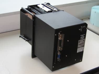
Click to zoom
Application Details
- Equipment Class
- DSS - Part 15 Spread Spectrum Transmitter
- Date of Grant
- Sep 28, 2004
- Application Purpose
- Original Equipment
- Date of Application
- Sep 28, 2004
- Equipment Note
- M8485e Printer with RFID reader
- Frequency Range
- 902.80000000 - 927.60000000
- Company
- Sato Corporation
- Country
- Japan
Documents & Files
Document Text
Text extracted from the exhibit documents filed with the FCC. Open a document above to read the original.
Users Manual
M-8485Se Quick Guide FCC COMPLIANCE This equipment has been tested and found to comply with the limits for a Class B digital device, pursuant to Part 15 of the FCC Rules. These limits are designed to provide reasonable protection against harmful interference in a residential installation. This equipment generates, uses, and can radiate radio frequency energy and, if not installed and used in accordance with the instructions, may cause harmful interference to radio communications. However, there is no guarantee that interference will not occur in a particular installation. If this equipment does cause harmful interference to radio or television reception, which can be determined by turning the equipment off and on, the user is encouraged to try and correct the interference by one or more of the following measures: — Reorient or locate the receiving antenna. — Increase the separation between the equipment and receiver. — Connect the equipment into an outlet on a circuit different from that to which the receiver is connected. — Consult the dealer or an experienced radio/TV technician for help. CAUTION Reader antennas should be positioned so that personnel in the area for prolonged periods may safety remain at least 20 cm (7.9 in) in an uncontrolled environment from the antenna's surface. See FCC OET Bulletin 56 "Hazards of radio frequency and electromagnetic fields" and Bulletin 65 "Human exposure to radio frequency electromagnetic fields." This device shall not be co-located with any other transmitting antenna. PN9001086 Rev A Page 1 DECLARATION OF CONFORMITY SATO America, Inc. 10350A Nations Ford Road, Charlotte, North Carolina 28273 TEL (704) 644-1650 declare under our sole responsibility that the product M-8485Se complies with Part 15 of the FCC Rules. Operation is subject to the following two conditions: (1) this device may not cause harmful interference, and (2) this device must accept any interference received, including interference that may cause undesired operation. M-8485Se Quick Guide Table of Contents Controls and Indicators ................................................................... 3 Operator Panel ................................................................... 3 LED Indicators .................................................................... 3 Adjustments ........................................................................ 3 Keys ..................................................................................... 4 Rear Panel Connections ..................................................... 4 Initial Setup ..................................................................................... 5 Connecting the Printer ........................................................ 5 Printing a Test Label ........................................................... 6 Configuring the Printer ........................................................ 7 Computer Connections ....................................................... 7 Windows Drivers ................................................................. 10 What to do if the printer won’t function ............................................. 10 Media and Supplies ......................................................................... 14 Options ............................................................................................ 14 Safety Considerations ...................................................................... 15 Safety Information ............................................................................ 16 This Quick Guide was prepared to get you up and running quickly. It will enable you to get your new SATO M-8485Se installed and printing with a minimum of effort. However, it is recommended that you familiarize yourself with the contents of the M-8485Se Operator and Technical Reference Manual for detailed descriptions so you will be able to properly use the printer to its full potential. PN9001086 Rev A Page 2 M-8485Se Quick Guide Safety Information PN9001086 Rev A Page 16 M-8485Se Quick Guide Safety Information PN9001086 Rev A Page 17 M-8485Se Quick Guide Safety Information PN9001086 Rev A Page 18 M-8485Se Quick Guide Safety Information PN9001086 Rev A Page 19
Cover Letter(s)
RE: Sato Corporation FCC ID: MMFM8485SE In response to your questions regarding the above application: 1) Please provide a external photograph exhibit of sufficient detail to show the outside of the device being approved. Additional photographs have been uploaded to the ATCB website. 2) Part of the internal photographs was uploaded as confidential. Note that internal photographs are not typically allowed to be considered confidential. Additionally, the confidentiality letter did not appear to ask for confidentiality on this. Please explain or provide further detail as necessary. Please remove the confidentiality request for internal photographs. 3) The device is labeled with a DoC mark consistent with Class B PC peripherals. Additionally, the users manual page 2 mentions Class B. However, the device cautions against using in a residential environment because it may cause interference. It appears that the Class A users manual statements were placed in the users manual, except they were labeled with Class B. Is this Class A or Class B. This will affect the labeling of the device and statements required in the users manual. Please explain and correct all necessary exhibits. The user manual has been updated to contain the FCC Class B warning: NOTE: This equipment has been tested and found to comply with the limits for a Class B digital device , pursuant to Part 15 of the FCC Rules. These limits are designed to provide reasonable protection against harmful interference in a residential installation. This equipment generates, uses, and can radiate radio frequency energy and, if not installed and used in accordance with the instructions, may cause harmful interference to radio communications. However, there is no guarantee that interference will not occur in a particular installation. If this equipment does cause harmful interference to radio or television reception, which can be determined by turning the equipment off and on, the user is encouraged to try and correct the interference by one or more of the following measures: — Reorient or locate the receiving antenna. — Increase the separation between the equipment and receiver. — Connect the equipment into an outlet on a circuit different from that to which the receiver is connected. — Consult the dealer or an experienced radio/TV technician for help. 4) Application for FCC ID: MMFCL4XXE appears to use the same module as this application, however there appears to be difference of conducted power between the 2 application. Please explain. The two devices use the same module. The output power setting is different for the two different devices. 5) The RF exposure information in the users manual appears to be missing the prohibition against co-location statements that are required as well. The statement has been added to the user’s manual and the revised manual has been uploaded to the ATCB website. 6) Please explain how average measurements were made. It is assumed that the device was in a 100% CW carrier for purposes of the test. However a large difference exists between peak and average measurements which suggests otherwise. Since this device has a narrow bandwidth it would be expected that the adjustment of the VBW would normally not show much difference. Note that calculations based upon worse case dwell time per frequency are typically used to correct for average measurements. Note that calculations of the timing diagrams provided would also suggest that a VBW of > 100 Hz or more would be necessary for any average measurements made should the device be OOK modulation during the test. The spurious signals above 1GHz were narrowband, and could be observed with a reduced resolution bandwidth (30kHz). When making the FCC measurement, with RBW = 1 MHz, the signals from the EUT were below the instrumentation noise floor. All of the measurements, as indicated in the test data, were of the noise floor, hence the difference between peak and average measurements. 7) FYI......Average time of occupancy according the Part 15.247 for 902-928 MHz with > 250 kHz hopping channel is based on 10 seconds, not 20 seconds. Noted. Thank you. 8) FYI.....The DoC in the users manual must show a United States responsible party according to 2.1077 The DoC now references a US address. This letter, along with the following documents (uploaded to the ATCB website) should answer these outstanding issues: External Photos #2.pdf M8485Se_QuickGuide-1 Regards, Mark Briggs
Cover Letter(s)
August 4, 2004 American TCB 6731 Whittier Ave. Suite C110 McLean VA. 22101 Gentlemen: The enclosed documents constitute a formal submittal and application for a Grant of Equipment Authorization pursuant to Subpart C of Part 15 of FCC Rules (CFR 47) regarding intentional radiators. Data within this report demonstrates that the equipment tested complies with the FCC limits for intentional radiators. Elliott Laboratories, as duly authorized agent prepared this submittal. A copy of the letter of our appointment as agent is enclosed. If there are any questions or if further information is needed, please contact Elliott Laboratories for assistance. Sincerely, Mark Briggs Vice President of Engineering MB/dmg Enclosures: Agent Authorization Letter Emissions Test Report with Exhibits
Cover Letter(s)
American Telecommunications Certification Body Inc. 6731 Whittier Ave, McLean, VA 22101 September 7, 2004 RE: Sato Corporation FCC ID: MMFM8485SE After a review of the submitted information, I have a few comments on the above referenced Application. 1) Please provide a external photograph exhibit of sufficient detail to show the outside of the device being approved. 2) Part of the internal photographs was uploaded as confidential. Note that internal photographs are not typically allowed to be considered confidential. Additionally, the confidentiality letter did not appear to ask for confidentiality on this. Please explain or provide further detail as necessary. 3) The device is labeled with a DoC mark consistent with Class B PC peripherals. Additionally, the users manual page 2 mentions Class B. However, the device cautions against using in a residential environment because it may cause interference. It appears that the Class A users manual statements were placed in the users manual, except they were labeled with Class B. Is this Class A or Class B. This will affect the labeling of the device and statements required in the users manual. Please explain and correct all necessary exhibits. 4) Application for FCC ID: MMFCL4XXE appears to use the same module as this application, however there appears to be difference of conducted power between the 2 application. Please explain. 5) The RF exposure information in the users manual appears to be missing the prohibition against co- location statements that are required as well. 6) Please explain how average measurements were made. It is assumed that the device was in a 100% CW carrier for purposes of the test. However a large difference exists between peak and average measurements which suggests otherwise. Since this device has a narrow bandwidth it would be expected that the adjustment of the VBW would normally not show much difference. Note that calculations based upon worse case dwell time per frequency are typically used to correct for average measurements. Note that calculations of the timing diagrams provided would also suggest that a VBW of > 100 Hz or more would be necessary for any average measurements made should the device be OOK modulation during the test. 7) FYI......Average time of occupancy according the Part 15.247 for 902-928 MHz with > 250 kHz hopping channel is based on 10 seconds, not 20 seconds. 8) FYI.....The DoC in the users manual must show a United States responsible party according to 2.1077 Timothy R. Johnson Examining Engineer mailto: [email protected] The items indicated above must be submitted before processing can continue on the above referenced application. Failure to provide the requested information may result in application termination. Correspondence should be considered part of the permanent submission and may be viewed from the Internet after a Grant of Equipment Authorization is issued. z Page 2 September 7, 2004 Please do not respond to this correspondence using the email reply button. In order for your response to be processed expeditiously, you must submit your documents through the AmericanTCB.com website. Also, please note that partial responses increase processing time and should not be submitted. Any questions about the content of this correspondence should be directed to the sender.
External Photos
SATO Corporation FCC ID: MMFM8485SE Outward appearance Front, right side and top of the printer Back, left side and bottom of the printer
ID Label/Location Info
Label Measurements (unit: mm) Material: Matt Silver Polyester (Thickness: 0.05mm), on Laminate Adhesive: Hot melt pressure sensitive adhesives, or Synthetic resin emulsion Label Position (Printer Back View) MODEL: M-8485Se FCC ID : MMFM8485SE
Internal Photos
Antenna system Antenna Board (Top) Antenna Board (Bottom) Antenna Holder Antenna & Reader Engine position Printer Back View Reader Engine Position Antenna Position
RF Exposure Info
MPE Calculations – M8485 Printer The device is not a portable device (i.e. intended to be worn on the body or be hand- held), so it is classified as being either a mobile device or a fixed mounted device. The user’s manual specifies a minimum separation distance of at least 20cm, consistent with this classification. FCC part 1.1310, Table 1 limits the power density for uncontrolled exposure. The power density, P d (mW/cm 2 ) calculated from the maximum EIRP, P t (mW) and the distance, d (m), between the transmitting antenna and the closest person, can be calculated using: P d = P t /(4 pd 2 ) Frequency MPE Limit (mW/cm 2 ) Output Power (mW) Max. Antenna Gain (dBi) EIRP (mW) Pd at 20cm (mW/cm 2 ) Distance where Pd = limit (cm) 902 to 928 MHz 0.60 121.6 2.0 192.8 0.04 5.1 As shown in the calculations above, the power density 20cm from the device is below the maximum permitted level for uncontrolled exposure.
Test Report
File: R56635 Page 1 of 17 Electromagnetic Emissions Test Report and Application for Grant of Equipment Authorization pursuant to FCC Part 15, Subpart C (15.247) FHSS Specifications for an Intentional Radiator on the Sato Corporation Model: SATO M8485SE Printer with RFID Reader FCC ID: MMFM8485SE GRANTEE: Sato Corporation 1-207, Onari-Cho, Omiya-ku Saitama-shi Saitama Japan, TEST SITE: Elliott Laboratories, Inc. 684 W. Maude Avenue Sunnyvale, CA 94086 REPORT DATE: August 4, 2004 FINAL TEST DATE: August 2 and August 3, 2004 AUTHORIZED SIGNATORY: ______________________________ Mark Briggs Vice President of Engineering Elliott Laboratories, Inc. is accredited by the A2LA, certificate number 2016-01, to perform the test(s) listed in this report. This report shall not be reproduced, except in its entirety, without the written approval of Elliott Laboratories, Inc. Elliott Laboratories, Inc. -- EMC Department Test Report Report Date: August 4, 2004 File: R56635 Page 2 of 17 Pages TABLE OF CONTENTS COVER PAGE..................................................................................................................................................................................1 TABLE OF CONTENTS...............................................................................................................................................................2 SCOPE.............................................................................................................................................................................................3 OBJECTIVE...................................................................................................................................................................................3 SUMMARY OF RESULTS...........................................................................................................................................................4 MEASUREMENT UNCERTAINTIES....................................................................................................................................5 EQUIPMENT UNDER TEST (EUT) DETAILS..........................................................................................................................6 GENERAL...................................................................................................................................................................................6 OTHER EUT DETAILS............................................................................................................................................................6 ENCLOSURE..............................................................................................................................................................................6 MODIFICATIONS....................................................................................................................................................................6 SUPPORT EQUIPMENT..........................................................................................................................................................7 EUT INTERFACE PORTS........................................................................................................................................................7 EUT OPERATION DURING TESTING..................................................................................................................................7 ANTENNA REQUIREMENTS................................................................................................................................................7 TEST SITE......................................................................................................................................................................................8 GENERAL INFORMATION....................................................................................................................................................8 CONDUCTED EMISSIONS CONSIDERATIONS................................................................................................................8 RADIATED EMISSIONS CONSIDERATIONS....................................................................................................................8 MEASUREMENT INSTRUMENTATION..................................................................................................................................9 RECEIVER SYSTEM.................................................................................................................................................................9 INSTRUMENT CONTROL COMPUTER..............................................................................................................................9 LINE IMPEDANCE STABILIZATION NETWORK (LISN)...............................................................................................9 POWER METER......................................................................................................................................................................10 FILTERS/ATTENUATORS...................................................................................................................................................10 ANTENNAS............................................................................................................................................................................10 ANTENNA MAST AND EQUIPMENT TURNTABLE....................................................................................................10 INSTRUMENT CALIBRATION...........................................................................................................................................10 TEST PROCEDURES.................................................................................................................................................................11 EUT AND CABLE PLACEMENT...................…
Text truncated - open the document above for the full version.
Test Setup Photos
Radiated Emissions Test Configuration Photographs Radiated Emissions Test Configuration Photographs Conducted Emissions Test Configuration Photographs Conducted Emissions Test Configuration Photographs
Contact Information
Applicant
Mamoru Kido(Group Manager)
Technical Contact
Elliott Laboratories Inc.Mark Briggs
[email protected]408 245 7800
684 W. Maude Avenue · Sunnyvale, California · United States
Test Firm
Elliott Laboratories LLCDavid Bare
Technical Specifications
| # | Rule Parts | Frequency Range | Power Output |
|---|---|---|---|
| 1 | 15C | 902.8 MHz - 927.6 MHz | 122.00 mW |
Other Applications from Sato Corporation

MMFSATOTR3-C302
Nov 06, 2014RFID Module
Equipment Class
DXX - Part 15 Low Power Communication Device Transmitter
MMFS8486EX-BT
Aug 04, 2014Bluetooth module
Equipment Class
DSS - Part 15 Spread Spectrum Transmitter
MMFSMP-WL
Jul 27, 2011Wireless LAN Board
Equipment Class
DTS - Digital Transmission System
MMFTH208-W1
Aug 17, 2010TH208-W1
Equipment Class
DTS - Digital Transmission System
MMFCT-BT1VIPER
Mar 25, 2008Bluetooth Module
Equipment Class
DSS - Part 15 Spread Spectrum Transmitter