MMFMB400Wireless Barcode Printer
Sato Corporation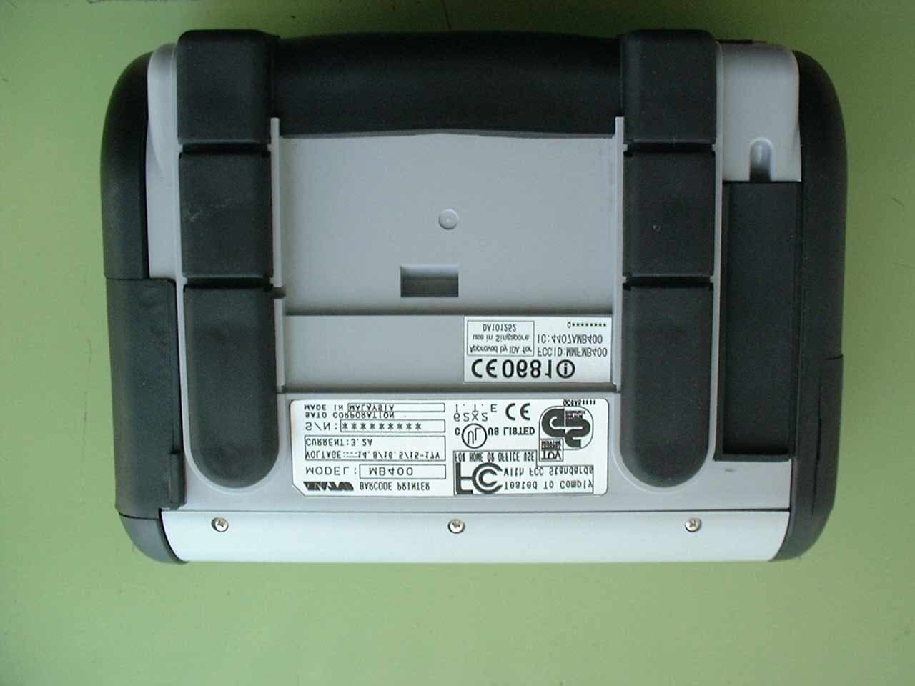
Click to zoom
Application Details
- Equipment Class
- DSS - Part 15 Spread Spectrum Transmitter
- Date of Grant
- Nov 26, 2002
- Application Purpose
- Original Equipment
- Date of Application
- Nov 26, 2002
- Equipment Note
- Wireless Barcode Printer
- Frequency Range
- 2402.00000000 - 2480.00000000
- Company
- Sato Corporation
- Country
- Japan
Documents & Files
Document Text
Text extracted from the exhibit documents filed with the FCC. Open a document above to read the original.
Users Manual
Thank you for your purchase of the SATO barcode printer MB400. Make sure to read this operation manual and keep it in a handy place. Quick Guide MB MB400 Barcode Printer 2 Thank you for your purchase of the SATO barcode printer MB400. This manual helps first time users understand the basics of the MB400 in a short period of time. To get the most out of the functions of the MB400, make sure to read this manual carefully. Warning! 1. This manual may not be reproduced whole or in part without prior consent from SATO. 2. The information in this manual is subject to change without notice. 3. Despite this manual has been created to be as accurate as possible, contact the shop or the dealer where you purchased this product if you find any errors or mistakes. Introduction This device complies with Part 15 of the FCC Rules.Operation is subject to the following two conditions:(1)This device may not cause harmful interference,and(2)This device must accept any interference received,including interference that may cause undesired operation. NOTE : This equipment has been tested and found to comply with the limits for a Class B digital device,pursuant to Part 15 of the FCC Rules. These limits are designed to provide reasonable protection against harmful interference in a residential installation.This equipment generates use and can radiate radio frequency energy and,if not installed and used in accordance with instructions,may cause harmful interference to radio communications.However,there is no guarantee that interference will not occur in a particular installation.If this equipment does cause harmful interference to radio or television reception,which can be determined by turning the equipment off and on,the user is encouraged to try to correct the interference by one or more of the following measures: -Reorient or relocate the receiving antenna. -Increase the separation between the equipment and receiver. -Connect the equipment into an outlet on a circuit different from that to whcih the receiver is connected. -Consult the dealer or an experienced radio/TV technician for help. 3 Features of the MB400 With compact and lightweight body combined with high performances, this printer prints barcodes clearly on various types of thermal paper. Excellent Printing Performance Not only does this printer print barcodes clearly, but it can also enlarge and print various types of fonts and Kanji characters in a free layout. Durable and Easy to Use This printer is also superb in durability, as it has been designed with the premises of printing barcodes. Also, special consideration has been taken so that the printer can be easily cleaned everyday. Dispenser Function As a portable printer, this printer can easily print and dispense labels to enable the application of labels at site. 4 Preparation/Operation Table of Contents 1. Safety Precautions .................................................................................... 5 Markings and Symbols ......................................................................... 5 Precautions in Use .............................................................................. 11 2. Unpacking ............................................................................................... 12 3. Part Names ............................................................................................. 13 Name and Function of Operating Parts .............................................. 15 4. Before Starting ........................................................................................ 16 Charging the Battery Pack .................................................................. 16 Installing and Removing the Battery Pack .......................................... 18 Setting Labels ..................................................................................... 20 5 Safety Precautions In this section, safety precautions about printer operation are explained to ensure proper care and usage. Make sure to read these carefully before using your printer. Markings and Symbols The following symbols or markings are used in this quick guide and on the printer so that you can properly use the printer, and to prevent any damage to property, harm or injury to yourself and others. Make sure to read their explanations carefully to familiarize yourself with their meanings. This symbol indicates information that, if ignored or applied incorrectly, creates the danger of death or serious personal injury. This symbol indicates information that, if ignored or applied incorrectly, creates the possibility of personal injury or property damage. Warning Caution Symbol example The triangle ( ) indicates something you should take absolute care when doing. The cautions are indicated concretely within the symbol. The symbol on the left indicates caution with electric shock. A diagonal line within a circle ( ) indicates something you should not do. The symbol on the left indicates you should not try to take the unit apart. A black circle ( ) indicates something you need to do. The symbol on the left indicates you should unplug the unit from the wall outlet. Safety Precautions 6 Safety Precautions Safety Precautions Warning Liquids Do not place any containers with water or chemicals, such as flower vases or cups, as well as small metallic objects near the printer. Continued use creates the danger of fire or electrical shock. * If any of these should fall into the printer, immediately turn off the power and contact your nearest dealer or service center. Foreign Matter Do not drop or insert metallic or flammable objects into the openings on the printer (such as outlets for cables). Continued use creates the danger of fire or electrical shock. * If any of these should fall into the printer, immediately turn off the power and contact your nearest dealer or service center. Dropping and Damage Do not use if the product has been dropped or damaged. Continued use creates the danger of fire and e…
Text truncated - open the document above for the full version.
Cover Letter(s)
Date: November 25, 2002 Federal Communications Commission Equipment Approval Services Subject: Request for Confidentiality FCC ID: MMFMB400 Dear Sir/Madame: Pursuant to Section 0.459 of the Commission’s Rules; we, Sato Corporation , hereby request confidentiality as below; 1. Circuit Diagrams 2. Parts List 3. Block Diagrams The reason of Confidentiality request is that trade secrets and proprietary information are enclosed in the above data, and the public disclosure of the data is harmful for us and will be made unjustifiable benefits to competitors. Sincerely,
External Photos
External Photographs - Front View - - Right Side View - - Left Side View - - Rear View - - Top View - - Bottom View -
ID Label/Location Info
Exhibit C Label and Label Placement EUT Bottom Face
Internal Photos
Internal Photographs - Open the Front Panel (1)- - Circuit Board (A side) - - Circuit Board (B side) - - TX Circuit Board Location - - TX Circuit Board (A side) - - TX Circuit Board (A side: Cover Open) - - TX Circuit Board (B side) –
Operational Description
Operational Description - Features of the MB400 - With compact and lightweight body combined with high performances, this printer prints barcodes clearly on various types of thermal paper. This printer is the thermal printer which publishes a bar code label etc. - Excellent Printing Performance - Not only does this printer print barcodes clearly, but it can also enlarge and print various types of fonts and Kanji characters in a free layout. - Durable and Easy to Use - This printer is also superb in durability, as it has been designed with the premises of printing barcodes. Also, special consideration has been taken so that the printer can be easily cleaned everyday. - Dispenser Function - As a portable printer, this printer can easily print and dispense labels to enable the application of labels at site. - Interface - Carry as an interface Bluetooth which is a 2.4GHz highly advanced smallness electric power data-communications system as a radio interface besides RS-232C, and TTL and IrDA. Bluetooth’s feature This unit has a second generation low power data communication system of Bluetooth as a 2.4GHz radio interface. With the Bluetooth’s feature of high interconnectivity, data can be exchanged with any Bluetooth enabled handheld terminals, barcode scanners, or PDA’s. Connection is made by specifying the BD address from devices like handheld terminal. With the use of a method called Frequency Hopping, Bluetooth interface is strong against noise and interference and has high confidentiality.
RF Exposure Info
RF Exposure Statement RF Exposure Statement RF Exposure Statement RF Exposure Statement FCC Caution FCC CautionFCC Caution FCC Caution IC(Industry Canada) IC(Industry Canada)IC(Industry Canada) IC(Industry Canada) Caution Caution Caution Caution CE CECE CE If you want to get a copy of the original Declaration of Conformity of our products which relates the R&TTE, please contact to web address :www.barcodesato.com. JAPAN QUALITY ASSURANCE ORGANIZATION 21-25, KINUTA 1-CHOME, SETAGAYA-KU, TOKYO 157-8573 JAPAN PHONE +81-3-3416-0111, FAX +81-3-3416-9691 Issue Date : November 15, 2002 Page 1 of 1 RF Exposure Calculation Exposure of Humans to RF Fields Requirements Applicant : Sato Corporation Type of Equipment : BARCODE PRINTER Model No. : MB400 FCC ID : MMFMB400 Regulations Applied : CFR 47 FCC 15.247(b)(5) References Documents : CFR 47 FCC 1.1307(b), 1.1310, 2.1093 and OET65 Supplement C RF Exposure Calculations : The following minimum separation distance between the EUT’s antenna and the human body was calculated in accordance with FCC OET65 Appendix B Table(B) “Limit for General Population / Uncontrolled Exposure”. The maximum permissible exposure level is defined with 1mW/cm 2 . The minimum separation distance where the exposure level reaches the permitted level can be calculated as bellow: Where: R = minimum separation distance in cm P = 0.414 mW (Max. conducted output power at antenna terminal) G = 1.64(numeric gain) = 2.14 dBi(Max. antenna Gain) S = 1.0 mW/cm 2 for 2.4 GHz (Max. permissible exposure level) Then minimum separation distance is 0.232 cm. Summary: The EUT complies with the RF exposure requirement of the above regulation. Masaaki Takahashi Senior Manager JQA EMC Engineering Dept. 2 4/*RGPS π= SGPR π 4/* =Q C O P Y
Test Report
JAPAN QUALITY ASSURANCE ORGANIZATION 21-25, KINUTA 1-CHOME, SETAGAYA-KU, TOKYO 157-8573 JAPAN PHONE +81-3-3416-0111, FAX +81-3-3416-9691 JQA APPLICATION NO.: 400-20287 Issue Date : November 15, 2002 Page 1 of 62 EMI TEST REPORT JQA APPLICATION NO. : 400-20287 Model No. : MB400 Type of Equipment : BARCODE PRINTER Regulations Applied : CFR 47 FCC Rules and Regulations Part 15 FCC ID : MMFMB400 Applicant : Sato Corporation Address : 1-207, ohnari-cho, Saitama-shi, Saitama-ken 331-0043, Japan Manufacture : Sato Corporation Address : 1-207, ohnari-cho, Saitama-shi, Saitama-ken 331-0043, Japan Received date of EUT : July 8, 2002 Final Judgment : Passed Test results in this report are obtained in use of equipment that is traceable to National Institute of Advanced Industrial Science and Technology (AIST) of Japan and Communication Research Laboratory (CRL) of Japan. The test results only respond to the tested sample. This report should not be reproduced except in full, without the written approval of JQA EMC Engineering Dept. Testing Div. C O P Y JQA Application No. :400-20287 FCC ID :MMFMB400 Model No. :MB400 Issue Date :November 15, 2002 Standard :CFR 47 FCC Rules Part 15 Page 2 of 62 JAPAN QUALITY ASSURANCE ORGANIZATION TABLE OF CONTENTS Page 1 Documentation 1.1 Test Regulation 4 1.2 General Information 4 1.3 Test Condition 5 – 11 1.4 EUT Modifications / Deviation from Standard 12 1.5 Test results 13 - 14 1.6 Summary 15 1.7 Test Configuration / Operation of EUT 16 1.8 EUT Arrangement (Drawing) 17 1.9 Preliminary Test and Test-setup (Drawings) 18 – 26 1.10 EUT Arrangement (Photographs) 27 - 29 C O P Y JQA Application No. :400-20287 FCC ID :MMFMB400 Model No. :MB400 Issue Date :November 15, 2002 Standard :CFR 47 FCC Rules Part 15 Page 3 of 62 JAPAN QUALITY ASSURANCE ORGANIZATION 2 Test Data 2.1 Channel Separation 30 2.2 Minimum Hopping Channel 31 – 32 2.3 Occupied Bandwidth 33 – 37 2.4 Dwell Time 38 – 42 2.5 Peak Output Power (Conduction) 43 2.6 Peak Output Power (Radiation) 44 2.7 Peak Power Density (Conduction) 45 - 46 2.8 Peak Power Density (Radiation) N/A 2.9 Spurious Emissions (Conduction) 47 - 49 2.10 Spurious Emissions (Radiation) 50 - 53 2.11 AC Power Line Conducted Emissions 54 - 55 2.12 RF Exposure Compliance 55 2.13 Spurious Emissions for Receiver (Radiation) 56 2.14 AC Power Line Conducted Emissions for Receiver 57 - 58 3 Appendix Test instruments List 59 - 62 C O P Y JQA Application No. :400-20287 FCC ID :MMFMB400 Model No. :MB400 Issue Date :November 15, 2002 Standard :CFR 47 FCC Rules Part 15 Page 4 of 62 JAPAN QUALITY ASSURANCE ORGANIZATION 1 DOCUMENTATION 1.1 TEST REGULATION FCC Rules and Regulations Part 15 Subpart B and Subpart C Test procedure : The tests were performed with reference to the FCC Public Notice DA 00-705, released March 30, 2000. The test set-up was made in accordance to the general provisions of ANSIC63.4-1992. 1.2 GENERAL INFORMATION 1.2.1 Test facility : 1) Test Facility located at EMC Engineering Dept. Testing Div. : - No.2 and 3 Anechoic Chambers(3 meters Site). - Shielded Enclosure. Expiration date of FCC test facility filing : May 27, 2005 2) EMC Engineering Dept. Testing Div. is recognized under the National Voluntary Laboratory accreditation Program for satisfactory compliance established in title 15, Part 285 Code of Federal Regulations. NVLAP Lab Code : 200189-0 (Effective through : June 30, 2003) 1.2.2 Description of the Equipment Under Test (EUT) : 1) Type of Equipment : BARCODE PRINTER 2) Product Type : Production 3) Category : Spread Spectrum Transmitter 4) EUT Authorization : Certification 5) FCC ID : MMFMB400 6) Trade Name : BARCODE PRINTER 7) Model No. : MB400 8) Operating Frequency Range : 2402 MHz - 2480 MHz 9) Highest Frequency Used in the EUT : 2480 MHz 10) RF Output Power : 1 mW(Rated) 11) Serial No. : 10400109 12) Date of Manufacture : Apr. 2001 13) Power Rating : DC 15-17V from the AC Adaptor 14) EUT Grounding : None 1.2.3 Definitions for symbols used in this test report : x - indicates that the listed condition, standard or equipment is applicable for this report. - indicates that the listed condition, standard or equipment is not applicable for this report. C O P Y JQA Application No. :400-20287 FCC ID :MMFMB400 Model No. :MB400 Issue Date :November 15, 2002 Standard :CFR 47 FCC Rules Part 15 Page 5 of 62 JAPAN QUALITY ASSURANCE ORGANIZATION 1.3 TEST CONDITION 1.3.1 The measurement of Channel Separation x - was performed. - was not applicable. Used test instruments : Type Number of test instruments (Refer to Appendix) Test Receiver TR07 Spectrum Analyzer N/A Cable CA11 Attenuator AU18 Antenna N/A 1.3.2 The measurement of Minimum Hopping Channel x - was performed. - was not applicable. Used test instruments : Type Number of test instruments (Refer to Appendix) Test Receiver TR07 Spectrum Analyzer N/A Cable CA11 Attenuator AU18 Antenna N/A 1.3.3 The measurement of Occupied Bandwidth x - was performed. - was not applicable. Used test instruments : Type Number of test instruments (Refer to Appendix) Test Receiver TR07 Spectrum Analyzer N/A Cable CA11 Attenuator AU18 Antenna N/A C O P Y JQA Application No. :400-20287 FCC ID :MMFMB400 Model No. :MB400 Issue Date :November 15, 2002 Standard :CFR 47 FCC Rules Part 15 Page 6 of 62 JAPAN QUALITY ASSURANCE ORGANIZATION 1.3.4 The measurement of Dwell Time x - was performed. - was not applicable. Used test instruments : Type Number of test instruments (Refer to Appendix) Test Receiver TR07 Spectrum Analyzer N/A Cable CA11 Attenuator AU18 Antenna N/A 1.3.5 The measurement of Peak Output Power and Density (Conduction) x - was performed. - was not applicable. Used test instruments : Type Number of test instruments (Refer to Appendix) Test Receiver TR07 Spectrum Analyzer N/A Cable CA11 Attenuator AU18 Antenna N/A Power Meter AU03 Power Sensor AU04 Signal Generator SG03 C O P Y JQA Application No. :400-20287 FCC ID :MMFMB400 Model No. :MB400 Issue Date :November 15, 2002 Standard :CFR 47 FCC Rules Pa…
Text truncated - open the document above for the full version.
Test Setup Photos
JAPAN QUALITY ASSURANCE ORGANIZATION 21-25, KINUTA 1-CHOME, SETAGAYA-KU, TOKYO 157-8573 JAPAN PHONE +81-3-3416-0111, FAX +81-3-3416-9691 1.10 TEST ARRANGEMENT (PHOTOGRAPHS) PHOTOGRAPHS OF EUT CONFIGURATION FOR RADIATED EMISSIONS MEASUREMENT Photograph present configuration with maximum emission JQA Application No. :400-20287 FCC ID :MMFMB400 Model No. :MB400 Issue Date :November 15, 2002 Standard :CFR 47 FCC Rules Part 15 Page 2 of 3 JAPAN QUALITY ASSURANCE ORGANIZATION PHOTOGRAPHS OF EUT CONFIGURATION FOR AC POWER LINE CONDUCTED EMISSIONS MEASUREMENT Photograph present configuration with maximum emission - Front View – - Side View – JQA Application No. :400-20287 FCC ID :MMFMB400 Model No. :MB400 Issue Date :November 15, 2002 Standard :CFR 47 FCC Rules Part 15 Page 3 of 3 JAPAN QUALITY ASSURANCE ORGANIZATION
Contact Information
Applicant
Mamoru Kido(Group Manager)
Test Firm
Japan Quality Assurance Org.Tetsuo Kato
Technical Specifications
| # | Rule Parts | Frequency Range | Power Output |
|---|---|---|---|
| 1 | 15C | 2.40 GHz - 2.48 GHz | 400.00 µW |
Other Applications from Sato Corporation

MMFSATOTR3-C302
Nov 06, 2014RFID Module
Equipment Class
DXX - Part 15 Low Power Communication Device Transmitter
MMFS8486EX-BT
Aug 04, 2014Bluetooth module
Equipment Class
DSS - Part 15 Spread Spectrum Transmitter
MMFSMP-WL
Jul 27, 2011Wireless LAN Board
Equipment Class
DTS - Digital Transmission System
MMFTH208-W1
Aug 17, 2010TH208-W1
Equipment Class
DTS - Digital Transmission System
MMFCT-BT1VIPER
Mar 25, 2008Bluetooth Module
Equipment Class
DSS - Part 15 Spread Spectrum Transmitter