MMFMP9310NT1RFID Reader Module
Sato Corporation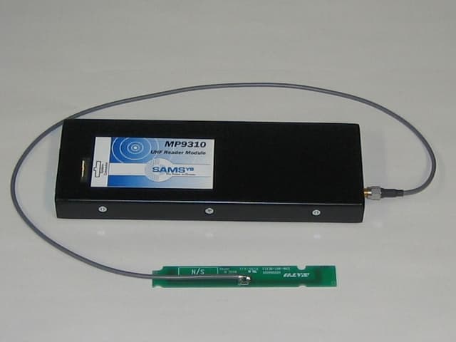
Click to zoom
Application Details
- Equipment Class
- DSS - Part 15 Spread Spectrum Transmitter
- Date of Grant
- Nov 13, 2005
- Application Purpose
- Original Equipment
- Date of Application
- Nov 13, 2005
- Equipment Note
- RFID Reader Module
- Frequency Range
- 903.10000000 - 926.90000000
- Company
- Sato Corporation
- Country
- Japan
Documents & Files
Document Text
Text extracted from the exhibit documents filed with the FCC. Open a document above to read the original.
External Photos
External View – Top/Front – MP9310 External View – Top/Rear – MP9310 Company: SATO CORPORATION Product: MP9310-NT FCC ID#: MMFMP9310NT1 Photo Description: Side #1 of Module and Side #1 of Antenna Assembly Connected Company: SATO CORPORATION Product: MP9310-NT FCC ID#: MMFMP9310NT1 Photo Description: Side #2 of Module and Side #2 of Antenna Assembly Connected
ID Label/Location Info
Company: SATO CORPORATION Product: MP9310-NT FCC ID: MMFMP9310NT1 Description: Label Information Measurements (unit: mm) Material: Matt Silver Polyester (Thickness: 0.05mm), on Laminate Adhesive: Hot melt pressure sensitive adhesives, or Synthetic resin emulsion MODEL: MP9310-NT FCC ID: MMFMP9310NT1 Company: SATO CORPORATION Product: MP9310-NT FCC ID: MMFMP9310NT1 Photo Description: Label Placement
Internal Photos
Internal Photos – MP9310 Component Side – Shields in Place Component Side – Shields Removed Solder Side
Schematics
Company: SATO CORPORATION Product: MP9310-NT FCC ID: MMFMP9310NT1 Description: Antenna description 1. Performance Form: Miniature Dipole Gain: -5dBi Coax: 1.5D-2V or equivalent coax cable Cable loss: 0.5dB Connector: SMA Antenna isn't possible to remove from the printer. 2. Outward appearance (Unit: mm)
Test Report
Test report No. : 26AE0124-HO-a Page : 2 of 42 Issued date : October 17 2005 Revised date : October 31, 2005 FCC ID : MMFMP9310NT1 UL Apex Co., Ltd. Head Office EMC Lab. 4383-326 Asama-cho, Ise-shi, Mie-ken 516-0021 JAPAN Telephone : +81 596 24 8116 Facsimile : +81 596 24 8124 MF060b(01.06.05) CONTENTS PAGE SECTION 1: Client information ............................................................................................................ 3 SECTION 2: Equipment under test (E.U.T.)........................................................................................ 3 SECTION 3: Test specification, procedures & results......................................................................... 5 SECTION 4: Operation of E.U.T. during testing .................................................................................8 SECTION 5: Conducted Emission....................................................................................................... 10 SECTION 6: Spurious Emission .......................................................................................................... 11 SECTION 7: 20dB Bandwidth ............................................................................................................. 12 SECTION 8: Maximum Peak Output Power ..................................................................................... 12 SECTION 9: Carrier Frequency Separation ...................................................................................... 12 SECTION 10: Number of Hopping Frequency .................................................................................. 12 SECTION 11: Dwell time...................................................................................................................... 12 APPENDIX 1: Photographs of test setup ............................................................................................ 13 Conducted Emission ....................................................................................................................................13 Spurious Emission (Radiated) ....................................................................................................................14 Worst Case Position (Horizontal: X-Axis/Vertical: Y-Axis) .....................................................................15 APPENDIX 2:Test instruments ..................................................................................................................16 APPENDIX 3: Data of EMI test............................................................................................................ 17 Conducted Emission ....................................................................................................................................17 Carrier Frequency Separation....................................................................................................................18 20dB Bandwidth...........................................................................................................................................20 Number of Hopping Frequency ..................................................................................................................22 Dwell time .....................................................................................................................................................24 Maximum Peak Output Power ...................................................................................................................26 Radiated Spurious Emission.......................................................................................................................28 Conducted Spurious Emission ....................................................................................................................37 99% Occupied Bandwidth ..........................................................................................................................42 Test report No. : 26AE0124-HO-a Page : 3 of 42 Issued date : October 17 2005 Revised date : October 31, 2005 FCC ID : MMFMP9310NT1 UL Apex Co., Ltd. Head Office EMC Lab. 4383-326 Asama-cho, Ise-shi, Mie-ken 516-0021 JAPAN Telephone : +81 596 24 8116 Facsimile : +81 596 24 8124 MF060b(01.06.05) SECTION 1: Client information Company Name : SATO CORPORATION Address : 1-207, Onari-cho, Omiya-ku, Saitama-shi, Saitama, 330-0852 Japan Telephone Number : +81-48-663-8118 Facsimile Number : +81-48-651-6662 Contact Person : Yukio Nagashima SECTION 2: Equipment under test (E.U.T.) 2.1 Identification of E.U.T. Type of Equipment : RFID Reader Module Model No. : MP9310-NT Serial No. : 11960 for Conducted Emission test 11943 for other tests Country of Manufacture : USA Receipt Date of Sample : September 6, 2005 Condition of EUT : Production model 2.2 Product Description Model No: MP9310-NT (referred to as the EUT in this report) is the RFID Reader Module. Frequency Hopping System (RF-ID) Equipment Type Transceiver Frequency Range 903.100MHz – 926.900MHz Method of Frequency Generation Synthsizer Type of Modulation FHSS Mode of Operation Duplex Antenna Type Miniature dipole Antenna Connector Type bulk-head mount SMA Antenna Gain -5 dBi Power Supply DC5V +/- 10% Operating Temperature -20-55 degree Feature of EUT The EUT and its antenna for performing communication with a RFID tag are built in Sato's RFID printer. The inlet (the RFID tag) which an IC chip was incorporated into is pasted on the label to use and in addition to the reading and writing of RFID; it can do a printout to the surface. In the surface, the text, the image, the bar code and so on can be printed out. The printout data which was entered from the host interface is analyzed inside the printer and is changed and is sent to RFID Reader module. The RFID Reader module communicates with the inlet (the RFID tag) which was converted to the label through the antenna. Reading of data, writing, etc. are performed between IC chips. When the writin…
Text truncated - open the document above for the full version.
Test Setup Photos
Test report No. : 26AE0124-HO-a Page : 13 of 42 Issued date : October 17 2005 Revised date : October 31, 2005 FCC ID : MMFMP9310NT1 UL Apex Co., Ltd. Head Office EMC Lab. 4383-326 Asama-cho, Ise-shi, Mie-ken 516-0021 JAPAN Telephone : +81 596 24 8116 Facsimile : +81 596 24 8124 MF060b(01.06.05) APPENDIX 1: Photographs of test setup Conducted Emission Front Rear *The test configuration is set up in the actual usage, which is in the worst conditions of the noise level. Test report No. : 26AE0124-HO-a Page : 14 of 42 Issued date : October 17 2005 Revised date : October 31, 2005 FCC ID : MMFMP9310NT1 UL Apex Co., Ltd. Head Office EMC Lab. 4383-326 Asama-cho, Ise-shi, Mie-ken 516-0021 JAPAN Telephone : +81 596 24 8116 Facsimile : +81 596 24 8124 MF060b(01.06.05) Spurious Emission (Radiated) Front Rear *The test configuration is set up in the actual usage, which is in the worst conditions of the noise level. Test report No. : 26AE0124-HO-a Page : 15 of 42 Issued date : October 17 2005 Revised date : October 31, 2005 FCC ID : MMFMP9310NT1 UL Apex Co., Ltd. Head Office EMC Lab. 4383-326 Asama-cho, Ise-shi, Mie-ken 516-0021 JAPAN Telephone : +81 596 24 8116 Facsimile : +81 596 24 8124 MF060b(01.06.05) Worst Case Position (Horizontal: X-Axis/Vertical: Y-Axis) X-Axis Y-Axis Z-Axis
Contact Information
Applicant
Mamoru Kido(Group Manager)
Technical Contact
UL Apex Co., LtdHiroka Umeyama
[email protected]+81-596-24-8116
4383-326 Asama-cho · Ise-shi, Mie-ken · Japan
Non-Technical Contact
UL Apex Co., LtdHisayuki Kioka
[email protected]+81-596-24-8116
Test Firm
UL Japan, IncMitsuru Fujimura
Technical Specifications
| # | Rule Parts | Frequency Range | Power Output |
|---|---|---|---|
| 1 | 15C | 903.1 MHz - 926.9 MHz | 283.79 mW |
Other Applications from Sato Corporation

MMFSATOTR3-C302
Nov 06, 2014RFID Module
Equipment Class
DXX - Part 15 Low Power Communication Device Transmitter
MMFS8486EX-BT
Aug 04, 2014Bluetooth module
Equipment Class
DSS - Part 15 Spread Spectrum Transmitter
MMFSMP-WL
Jul 27, 2011Wireless LAN Board
Equipment Class
DTS - Digital Transmission System
MMFTH208-W1
Aug 17, 2010TH208-W1
Equipment Class
DTS - Digital Transmission System
MMFCT-BT1VIPER
Mar 25, 2008Bluetooth Module
Equipment Class
DSS - Part 15 Spread Spectrum Transmitter