MMFRWMTM1RFID Reader
Sato Corporation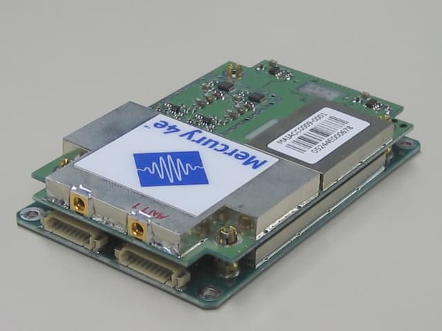
Click to zoom
Application Details
- Equipment Class
- DSS - Part 15 Spread Spectrum Transmitter
- Date of Grant
- Mar 21, 2006
- Application Purpose
- Original Equipment
- Date of Application
- Mar 12, 2006
- Equipment Note
- RFID Reader
- Frequency Range
- 902.99000000 - 927.18600000
- Company
- Sato Corporation
- Country
- Japan
Documents & Files
Document Text
Text extracted from the exhibit documents filed with the FCC. Open a document above to read the original.
Users Manual
3/17/2006 ThingMagic 1/7 Mercury4e™ Specification Sheet Mercury4e Specification Sheet v1.3 3/17/2006 ThingMagic 2/7 Table of Contents 1. Introduction....................................................................................................................... 3 2. Mercury4e™ Reader Specification Overview ................................................................. 3 3. Physical Connection and Pin-Out ..................................................................................... 5 4. Protocol Support ............................................................................................................... 5 5. Mechanical Drawing ......................................................................................................... 6 6. Regulatory Installation Requirements............................................................................... 7 7. End Product Labeling ....................................................................................................... 7 Mercury4e Specification Sheet v1.3 3/17/2006 ThingMagic 3/7 1. Introduction The Mercury4e™ is ThingMagic’s entry in the embedded reader market, which comprises label printers, label applicators, and handheld terminals. Unlike previous members of ThingMagic’s Mercury family, the Mercury4e™ readers are designed for embedded applications within a host system. They interface with a host system via asynchronous serial (TTL-level RS-232) using a packetized polled mode communication. Anti-collision capability is not provided in the initial release of the Mercury4e product. Mercury4e™ readers have a single on-board processor, a TI 55xx series DSP. The reader operates in a single-tasking, streaming mode where tag IDs are sent back to the host processor one-at-a-time, in a mode suitable for small tag populations where reading occurs primarily when triggered by the host system. This is envisioned to occur in response to the host system’s request when a label is aligned beneath the print head in a printer application. 2. Mercury4e™ Reader Specification Overview Requirement Value Dimensions 5.5cm x 9cm x 1.5cm RFID Tag and Protocol Support Host-switched multi-protocol: EPC Global Class 0 (including Symbol and Impinj Class 0+ R/W) EPC Class 1 R/W (64 and 96 bit silicon) EPC Generation 2 R/W* ISO18000-6B R/W Frequency 902-928 MHz, for FHSS use and certification in the US and Canada RFID Tag Read and Write Rates Read/write rate and range is protocol dependent and will vary depending on RF signal strength and other environmental factors. Antenna Connectors 2 MMCX connectors for two antennas. Unit will tolerate 2:1 VSWR without damage, but a VSWR below 1.5:1 will be needed for best performance. Circular polarization is supported. Module Power Supply Fixed 5.3 VDC +/- 4% DC supply voltage, average power dependent on duty cycle. Peak power not more than 8.8W. Power supply ripple and noise must be less than 100mV pp, and the host power supply load transient response must support a dI/dT of 500kA/s with less than 100mV over/undershoot. RF Power Output RF power output depends on available peak supply current. RF output power is variable in 0.1dB steps from 20dBm to 24dBm. Absolute accuracy of RF output power is +/- 1dB. Mercury4e Specification Sheet v1.3 3/17/2006 ThingMagic 4/7 Requirement Value Sleep Mode The module can be put in and out of sleep mode by the host processor. Host Communication 3.3/5V logic level, async serial according to ThingMagic’s MercuryE Communication Protocol Document. The serial interface includes the settings 115.2 and 38.4 kbaud, 8,n,1, no flow control. Firmware Firmware is upgradeable via serial port. Unit first boots into a write-protected bootloader region, verifies CRC of the full firmware image, waits for a Go (or Firmware Upload) command from the host system, and then runs that firmware image. If a valid image is not found by the bootloader, the bootloader waits for a Firmware Upload per the Communication Protocol Document. Temperature Operating and Storage Operating ambient temp range 0C-60C. Storage temp range better than –40C to +85C. ESD 10kV to antenna shield conductor. Recommend the use of an antenna that presents a DC short to endure 10kV- this is TBD pending testing. Regulatory FCC Class B (digital portion) and 15.247 (FHSS radio): Test commands for type acceptance testing will be provided. Certification Certification by OEM customer Mercury4e Specification Sheet v1.3 3/17/2006 ThingMagic 5/7 3. Physical Connection and Pin-Out The host connector is an AMP part number 4-440372-2 right angle male 1.27mm header. It mates with an AMP part number 1-440146-0 socket and 440147-1 pins. Pin Number Function 1 5.3 VDC +/- 4% 2 5.3 VDC +/- 4% 3 Ground 4 Ground 5 Output 1 (GPIO from module) 6 Output 2 (GPIO from module) 7 Input 1 (GPIO to module) 8 Input 2 (GPIO to module) 9 Asynchronous Serial RX (from host to module) 10 Asynchronous Serial TX (from module to host) 4. Protocol Support ThingMagic will provide the following air interface protocols and functionality. Additional protocols and their functionality will be provided on a quoted basis. ID Read ID Write Data Read Data Write Password Write Lock EPC Global Class 0 (including Symbol and Impinj Class 0+ R/W) 9 9 9 (0+)9 (0+) 9 (0+) EPC Class 1 (V1) 9 9 9 9 EPC UHF Gen2 9 9 9 9 9 9 ISO 18000-6b 9 9 9 Mercury4e Specification Sheet v1.3 3/17/2006 ThingMagic 6/7 5. Mechanical Drawing Mercury4e Specification Sheet v1.3 3/17/2006 ThingMagic 7/7 6. Regulatory Installation Requirements This device is intended for OEM integrators only. It is the OEM integrator’s responsibility to obtain FCC modular authorization for this device. Once authorized it must be used only under the following conditions: 1) The antenna must be installed such that 20 cm is maintained between the antenna and users, and 2) The transmitter module may not be co-located with any other transmitter or antenna. As long as the two conditions above are met, further trans…
Text truncated - open the document above for the full version.
Cover Letter(s)
FCCill: MMFRWMTMI Model: Mercury4e Applicant:SATOCORPORATION 3 March2006 <::7 ThingMagicSI!, " ReauestforModularApproval Themodulartransmitter(Model:Mercury4e)isdesignedbyThingMagicInc. Thismodulartransmittercanbeequippedonanydevice,if thedistancebetweentheradiatorandperson'sbody keepatleast20cmormore.Themodulartransmittercompliesthemodulebasicrequirement(Item1 to8)inFCC PublicNotice:Part15UnlicensedModularTransmitterApproval(DAOO-1407)asindicatedbelow: [Modulebasicrequirement] (1)HaveitsownRFshielding.:Thismodulartransmitterhasit ownRFshielding.PleaserefertotheAlPhoto. AlPhoto(Modulartransmitter) (2)Themodulartransmittermusthavebufferedmodulation/datainputs.:DatainputtoModulartransmitteris controlledasnotgeneratingexcessivedataspeedandabnormalmodulation. (3)Themodulartransmittermusthaveitsownpowersupplyregulation.:ThemodulecanregulatePowerSupply byitself.(SeeSchematic) (4)ThemodulartransmittermustcomplywiththeantennarequirementsofSection15.203and15.204(c).:The antennaisconnectedtothemodulewithuniqueconnectorandinstallinsideoftheendproduct.So,it is impossibleforenduserstodisconnectit.Accordingly,it iscomplied. (5)Themodulartransmittermustbetestedina standalone.:Themodulartransmitterhasbeenperformedthe testingasastandaloneandthenconfIrmedthecompliance.PleaserefertotheTestreport.(No. 26FEO133-YK-F1) (6)ThemodulartransmittermustbelabeledwithitsownFCCill,and,if theFCCillis notvisiblewhenthe moduleis installedinsideanotherdevice,thentheoutsideofthedeviceintowhichthemoduleis installed mustalsodisplaya labelreferringtotheenclosedmodule.:Thismodulartransmitteris compliedwiththis requirement.PleaserefertothefileofLabeldrawingandlocation. (7)ThemodulartransmittermustcomplywithanyspecifIcruleoroperatingrequirementsapplicabletothe transmitterandthemanufacturermustprovideadequateinstructionsalongwiththemoduletoexplainany suchrequirements.:Thenecessaryexplanationtobecompliedwiththisrequirementiscontainedinthe manual. (8)ThemodulartransmittermustcomplywithanyapplicableRFexposurerequirements.:Themodular transmittercomplieswithFCCradiationexposurerequirementspecifIedintheFCCRules15.247(i).Please referto~osurestatement. TomGrant CEO,ThingMagic,Inc. OneBroadway,Cambridge,MA02142. Tel:+ 1 866.833.4069. Fax:+ 1 617.225.4410. www.thingmagic.com
Cover Letter(s)
American Telecommunications Certification Body Inc. 6731 Whittier Ave, McLean, VA 22101 March 12, 2006 RE: SATO Corporation FCC ID: MMFRWMTM1 After a review of the submitted information for FCC, I have a few comments on the above referenced Application. FCC Review 1) Recent information from the FCC has stated that the confidentiality letter must be signed by the contact of the grantee given on the FCC site, or by the laboratory if the lab has been given authority to do so. Please note that currently the confidentiality letter comes from the manufacturer only, not the applicant or lab. Please correct. 2) The device appears large enough that the labeling should include the 2 part statement on the label. Note this information may alternatively be placed in the manual is the device is smaller than 8x10 cm. Please correct. This device complies with part 15 of the FCC Rules. Operation is subject to the following two conditions: (1) This device may not cause harmful interference, and (2) this device must accept any interference received, including interference that may cause undesired operation 3) It appears that this device consists of 2 boards and the label is actually placed on the digital board and not the TX board. Ideally the label should be placed upon the host, or in this case the TX board. Please consider relocating the label. 4) Information received by emails suggests you client may not want to receive the grant until March 15. Please kindly confirm. 5) The 731 form cites a DTS device. However this device appears to be submitted as a DSS device. Please review and/or correct the 731. 6) Please provide photographs/description of the antennas approved for use with this device. Please include photos, manufacturers, gains, etc. 7) Users manual appears to be missing information required by 15.21, 15.105, non-colocation requirements, and other detailed information that should be provided to the integrator regarding modular approval. Please see example information (attached) that covers various items that should be discussed or covered in the manual. 8) Manual suggest user definable power up to 30 dBm. Please note that FCC expects device to be tested as worse case power output. It appears that this may not have been done. Please review. Additionally, please note that allowing user to adjust power above approved levels is also not allowed per 15.15. 9) Page 3 of the test report cites a 200 kHz spacing, while data suggests something different (470 kHz). Please review. 10) DSS devices should include information on the following items: a) pseudo random sample hopping list and how the pseudo random channels are selected. b) description of system receivers and how they have input bandwidths that match the hopping channel bandwidths of their corresponding transmitters and how they shift frequencies in synchronization with the transmitted signals c) How the device meets 15.247(g) and (h). d) If the system has different modes of operation that affect the above, the theory should cover each of these as well (i.e. different timing, data rates, etc). e) What is the return frequency from tags. z Page 2 March 12, 2006 Timothy R. Johnson Examining Engineer mailto: [email protected] The items indicated above must be submitted before processing can continue on the above referenced application. Failure to provide the requested information may result in application termination. Correspondence should be considered part of the permanent submission and may be viewed from the Internet after a Grant of Equipment Authorization is issued. Please do not respond to this correspondence using the email reply button. In order for your response to be processed expeditiously, you must submit your documents through the AmericanTCB.com website. Also, please note that partial responses increase processing time and should not be submitted. Any questions about the content of this correspondence should be directed to the sender.
Cover Letter(s)
Reply to ATCB’s comments on March 12, 2006 FCC ID: MMFRWMTM1 1) Recent information from the FCC has stated that the confidentiality letter must be signed by the contact of the grantee given on the FCC site, or by the laboratory if the lab has been given authority to do so. Please note that currently the confidentiality letter comes from the manufacturer only, not the applicant or lab. Please correct. ==> Please find uploaded “Revised Request_for_Confidentiality.pdf”. 2) The device appears large enough that the labeling should include the 2 part statement on the label. Note this information may alternatively be placed in the manual is the device is smaller than 8x10 cm. Please correct. This device complies with part 15 of the FCC Rules. Operation is subject to the following two conditions: (1) This device may not cause harmful interference, and (2) this device must accept any interference received, including interference that may cause undesired operation ==>Please find uploaded "Revised FCC Label Drawing and Location.pdf". 3) It appears that this device consists of 2 boards and the label is actually placed on the digital board and not the TX board. Ideally the label should be placed upon the host, or in this case the TX board. Please consider relocating the label. ==> The Applicant does not have space to affix the label on TX board. 4) Information received by emails suggests you client may not want to receive the grant until March 15. Please kindly confirm. ==> The applicant would like to receive it as soon as possible. 5) The 731 form cites a DTS device. However this device appears to be submitted as a DSS device. Please review and/or correct the 731. ==> Please find uploaded "Revised Form731.pdf". 6) Please provide photographs/description of the antennas approved for use with this device. Please include photos, manufacturers, gains, etc. ==> Please find uploaded "Operational Description (Antenna description)[Confidential].pdf". 7) Users manual appears to be missing information required by 15.21, 15.105, non-colocation requirements, and other detailed information that should be provided to the integrator regarding modular approval. Please see example information (attached) that covers various items that should be discussed or covered in the manual. ==> Please find uploaded “Revised Installation Manual.pdf”. 8) Manual suggest user definable power up to 30 dBm. Please note that FCC expects device to be tested as worse case power output. It appears that this may not have been done. Please review. Additionally, please note that allowing user to adjust power above approved levels is also not allowed per 15.15. ==> Please find uploaded “Revised Installation Manual.pdf”. 9) Page 3 of the test report cites a 200 kHz spacing, while data suggests something different (470 kHz). Please review. ==> Please find uploaded "Revised FCC Test Report.pdf". 10) DSS devices should include information on the following items: a) pseudo random sample hopping list and how the pseudo random channels are selected. b) description of system receivers and how they have input bandwidths that match the hopping channel bandwidths of their corresponding transmitters and how they shift frequencies in synchronization with the transmitted signals c) How the device meets 15.247(g) and (h). d) If the system has different modes of operation that affect the above, the theory should cover each of these as well (i.e. different timing, data rates, etc). e) What is the return frequency from tags. ==> Please find uploaded “Operational Description 2 (Confidential).pdf”
External Photos
Company: SATO CORPORATION Product: Mercury4e FCC ID: MMFRWMTM1 Photo Description: Front, right side and top of the Reader module Company: SATO CORPORATION Product: Mercury4e FCC ID: MMFRWMTM1 Photo Description: Label Placement
ID Label/Location Info
Company: SATO CORPORATION Product: Mercury4e FCC ID: MMFRWMTM1 Description: Label Information (for Reader Module) Measurements (unit: mm) Material: Matt Silver Polyester (Thickness: 0.05mm), on Laminate Adhesive: Hot melt pressure sensitive adhesives, or Synthetic resin emulsion Company: SATO CORPORATION Product: Mercury4e FCC ID: MMFRWMTM1 Photo Description: Label Placement
Internal Photos
ThingMagic Mercury4e Analog Bottom ThingMagic Mercury4e Analog Cover ThingMagic Mercury4e Analog Top ThingMagic Mercury4e Digital Bottom ThingMagic Mercury4e Digital Cover ThingMagic Mercury4e Digital Top
RF Exposure Info
Applicant: SATO CORPORATION T ype of Equipment : RFID Reader/Writer Module Model No. : Mercury 4e FCC ID: MMFRWMTM1 SATO CORPORATION declares that Model : RFID Reader/Writer Module complies with FCC radiation exposure requirement specified in the FCC Rules 2.1091. The “Mercury 4e“ has 289.73 mW of conducted Peak Output power and 91.62 mW of EIRP. The Following calculation is the reference data for 20cm distance for mobile use. RF Exposure Calculations: The following information provides the minimum separation distance for the highest gain antenna provided with the “Mercury 4e“ as calculated from FCC OET Bulletin 65 Appendix A, Table (B) Limits for General Population / Uncontrolled Exposure. This calculation is based on the highest EIRP possible from the system, considering maximum power and antenna gain, and considering a 0.6.0mW/cm^2 uncontrolled exposure limit. The Friis formula used was: S = (P * G) / (4 * π * r 2 ) Where P = 289.73 mW (Maximum peak output power) G = 0.32 Numerical Antenna gain; equal -5 dBi r =20.0 cm For: Mercury 4eS = 0.01823mW/cm 2 RF Exposure for Mobile use No. : 26FE0133-YK-F1
Test Report
FCC ID : MMFRWMTM1 Test report No. : 26FE0133-YK-F1 Page : 1 of 53 Issued date : March 2, 2006 UL Apex Co., Ltd. YAMAKITA EMC LAB. 907 Kawanishi, Yamakita-machi, Ashigarakami-gun, Kanagawa-ken, 258-0124 JAPAN Telephone: +81 465 77 1011 Facsimile: +81 465 77 2112 MF060b(12.02.06) EMI TEST REPORT Test Report No. : 26FE0133-YK-F1 Applicant : SATO CORPORATION Type of Equipment : RFID Reader/Writer Module Model No. : Mercury 4e FCC ID : MMFRWMTM1 Test Standard : FCC Part15 Subpart C, Section 15.207, Section 15.209, Section 15.247: 2005 Test Result : Complied 1. This test report shall not be reproduced except in full, without the written approval of UL Apex Co., Ltd. 2. The results in this report apply only to the sample tested. 3. This equipment is in compliance with above regulation. We hereby certify that the data contain a true representation of the EMC profile. 4. The test results in this test report are traceable to the national or international standards. Date of test: February 16, 17 and 28, 2006 Tested by: Makoto Hosaka Approved by: Osamu Watatani Site Manager of Yamakita EMC Lab. FCC ID : MMFRWMTM1 Test report No. : 26FE0133-YK-F1 Page : 2 of 53 Issued date : March 2, 2006 UL Apex Co., Ltd. YAMAKITA EMC LAB. 907 Kawanishi, Yamakita-machi, Ashigarakami-gun, Kanagawa-ken, 258-0124 JAPAN Telephone: +81 465 77 1011 Facsimile: +81 465 77 2112 MF060b(12.02.06) Table of Contents Page 1 Applicant Information 3 2 Product Description 3 3 Test Specification, Procedures and Results 4 4 System Test Configuration 6 5 Conducted Emission 8 6 Carrier Frequency Separation 9 7 20dB Bandwidth 9 8 Number of Hopping Frequency 9 9 Dwell Time 9 10 Maximum Peak Output Power 9 11 Out of Band Emissions (Antenna Port Conducted) 9 12 Out of Band Emissions (Radiated) 10 Contents of Appendixes 11 APPENDIX 1: Photographs of test setup 12 APPENDIX 2: Test Data 15 APPENDIX 3: Test instruments 53 FCC ID : MMFRWMTM1 Test report No. : 26FE0133-YK-F1 Page : 3 of 53 Issued date : March 2, 2006 UL Apex Co., Ltd. YAMAKITA EMC LAB. 907 Kawanishi, Yamakita-machi, Ashigarakami-gun, Kanagawa-ken, 258-0124 JAPAN Telephone: +81 465 77 1011 Facsimile: +81 465 77 2112 MF060b(12.02.06) 1 Applicant Information Company Name : SATO CORPORATION Brand Name : SATO CORPORATION Address : 1-207 Onari-cho, Omiya-ku, Saitama-shi, Saitama-ken, 330-0852 JAPAN Telephone Number : +81 48 663 8118 Facsimile Number : +81 48 651 6662 Contact Person : Yukio Nagashima 2 Product Description Type of Equipment : RFID Reader/Writer Module Model No. : Mercury 4e Serial No. : 05434E00E008 Rating : DC5.3V, 2.5A Country of Manufacture : U.S.A Receipt Date of Sample : February 3, 2006 Condition of EUT : Production model Clock frequency 16MHz, 20MHz Equipment type Transceiver Frequency band Lower limit 902.990MHz Upper limit 927.186MHz Channel spacing 470kHz/CH Type of Modulation FHSS Antenna type Miniature dipole Antenna connector type MMCX Antenna gain -5dBi Antenna cable loss 0.675dB Mode of Operation Duplex ITU code A1D Power supply (Inner) DC 5.3V ±5% Operating temperature range 0 to +55 deg.C. FCC Part15.31 (e) Host device provides the module with stable power supply (DC 1.28 and 3.3 V), therefore the equipment complies power supply regulation. FCC Part15.203 Antenna requirement The equipment and its antenna comply with this requirement. Since this antenna is connected with unique connector and installed in the end product (Printer), it cannot be replaced by end users. FCC ID : MMFRWMTM1 Test report No. : 26FE0133-YK-F1 Page : 4 of 53 Issued date : March 2, 2006 UL Apex Co., Ltd. YAMAKITA EMC LAB. 907 Kawanishi, Yamakita-machi, Ashigarakami-gun, Kanagawa-ken, 258-0124 JAPAN Telephone: +81 465 77 1011 Facsimile: +81 465 77 2112 MF060b(12.02.06) 3 Test Specification, Procedures and Results 3.1 Test specification Test specification : FCC Part15 Subpart C: 2006 Title : FCC 47CFR Part15 Radio Frequency Device Subpart C Intentional Radiators Section 15.207: Conducted limits Section 15.209 Radiated emission limits, general requirements Section 15.247 Operation within the bands 902-928MHz, 2400-2483.5MHz, and 5725-5850MHz 3.2 Procedures & Results Item Test Procedure Specification RemarksDeviation Worst Margin Results Conducted emission ANSI C63.4:2003 7. AC powerline conducted emission measurements Section 15.207 - N/A 6.6dB (0.2116MHz, L1, AV, Tx 902.990MHz) Complied Carrier Frequency Separation ANSI C63.4:2003 13. Measurement of intentional radiators Section15.247 (a)(1) ConductedN/A Complied 20dB Bandwidth ANSI C63.4:2003 13. Measurement of intentional radiators Section15.247 (a)(1) ConductedN/A Complied Number of Hopping Frequency ANSI C63.4:2003 13. Measurement of intentional radiators Section15.247 (a)(1)(iii) ConductedN/A Complied Dwell Time ANSI C63.4:2003 13.Measurement of intentional radiators Section15.247 (a)(1)(iii) ConductedN/A Complied Maximum Peak Output Power ANSI C63.4:2003 13. Measurement of intentional radiators Section15.247 (b)(1) ConductedN/A *See data. Complied Spurious Emission ANSI C63.4:2003 13. Measurement of intentional radiators Section15.209 Section15.247(d) Conducted / Radiated N/A 5.4dB (959.24MHz, Horizontal, Tx 902.990MHz) Complied The measurements also referred to FCC Public Notice DA 00-705 "Guidance on Measurement for Frequency Hopping Spread Spectrum Systems". * No addition, exclusion nor deviation has been made from the standard. FCC ID : MMFRWMTM1 Test report No. : 26FE0133-YK-F1 Page : 5 of 53 Issued date : March 2, 2006 UL Apex Co., Ltd. YAMAKITA EMC LAB. 907 Kawanishi, Yamakita-machi, Ashigarakami-gun, Kanagawa-ken, 258-0124 JAPAN Telephone: +81 465 77 1011 Facsimile: +81 465 77 2112 MF060b(12.02.06) 3.3 Uncertainty Conducted emission The measurement uncertainty (with 95% confidence level) for this test is ±2.7dB. The data listed in this test report has enough margin, more than site margin. Antenna port conducted test The measurement uncertainty (with 95% confidence level) for this test is ±0.4dB. Spurious emission test (…
Text truncated - open the document above for the full version.
Test Setup Photos
FCC ID : MMFRWMTM1 Test report No. : 26FE0133-YK-F1 Page : 12 of 53 Issued date : March 2, 2006 UL Apex Co., Ltd. YAMAKITA EMC LAB. 907 Kawanishi, Yamakita-machi, Ashigarakami-gun, Kanagawa-ken, 258-0124 JAPAN Telephone: +81 465 77 1011 Facsimile: +81 465 77 2112 MF060b(12.02.06) Conducted emission FCC ID : MMFRWMTM1 Test report No. : 26FE0133-YK-F1 Page : 13 of 53 Issued date : March 2, 2006 UL Apex Co., Ltd. YAMAKITA EMC LAB. 907 Kawanishi, Yamakita-machi, Ashigarakami-gun, Kanagawa-ken, 258-0124 JAPAN Telephone: +81 465 77 1011 Facsimile: +81 465 77 2112 MF060b(12.02.06) Radiated emission FCC ID : MMFRWMTM1 Test report No. : 26FE0133-YK-F1 Page : 14 of 53 Issued date : March 2, 2006 UL Apex Co., Ltd. YAMAKITA EMC LAB. 907 Kawanishi, Yamakita-machi, Ashigarakami-gun, Kanagawa-ken, 258-0124 JAPAN Telephone: +81 465 77 1011 Facsimile: +81 465 77 2112 MF060b(12.02.06) Pre check of worse-case position Module: X-axis, Antenna: X-axis Module: Y-axis, Antenna: X-axis Module: Z-axis, Antenna: X-axis Module: Z-axis, Antenna: Y-axis Module: Z-axis, Antenna: Z-axis
Contact Information
Applicant
Mamoru Kido(Group Manager)
Technical Contact
UL Apex Co., Ltd.Toyokazu Imamura
[email protected]81 465 77 1011
907 Kawanishi, Yamakita-machi · Ashigarakami-gun, Kanagawa-ken · Japan
Non-Technical Contact
UL Apex Co., Ltd.Keijiro Kumagai
[email protected]81 596 24 8116
Test Firm
UL Japan, Inc. Yokowa EMC Lab.Masamichi Ishii
Technical Specifications
| # | Rule Parts | Frequency Range | Power Output |
|---|---|---|---|
| 1 | 15C | 902.99 MHz - 927.186 MHz | 290.00 mW |
Other Applications from Sato Corporation

MMFSATOTR3-C302
Nov 06, 2014RFID Module
Equipment Class
DXX - Part 15 Low Power Communication Device Transmitter
MMFS8486EX-BT
Aug 04, 2014Bluetooth module
Equipment Class
DSS - Part 15 Spread Spectrum Transmitter
MMFSMP-WL
Jul 27, 2011Wireless LAN Board
Equipment Class
DTS - Digital Transmission System
MMFTH208-W1
Aug 17, 2010TH208-W1
Equipment Class
DTS - Digital Transmission System
MMFCT-BT1VIPER
Mar 25, 2008Bluetooth Module
Equipment Class
DSS - Part 15 Spread Spectrum Transmitter