MMFSATOTR3RFID Reader/Writer Module Transmitter
Sato Corporation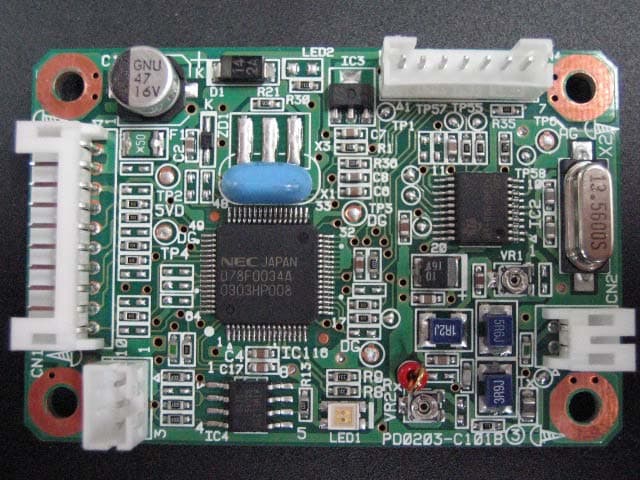
Click to zoom
Application Details
- Equipment Class
- DXX - Part 15 Low Power Communication Device Transmitter
- Date of Grant
- Jul 25, 2004
- Application Purpose
- Original Equipment
- Date of Application
- Jul 25, 2004
- Equipment Note
- RFID Reader/Writer Module Transmitter
- Frequency Range
- 13.56000000 - 13.56000000
- Company
- Sato Corporation
- Country
- Japan
Documents & Files
Document Text
Text extracted from the exhibit documents filed with the FCC. Open a document above to read the original.
Users Manual
Installation Turn the Power OFF and unplug the power cable before installation. 1. Remove the Cover LH Remove the screws ( 4 positions) 2. Install the RFID Interface Board ASSY Plug in the Interface Board and fix it on the printer with two screws. 3. Install the RFID Module Board ASSY The assembly of the eight spacers is carried out to Module BR. RSDRV board is fixed with four screws. Signal cable is fixed on tie lap. RFID module is fixed with four screws. The signal cable which has come out of the DRV board is connected to the connector (CN1) of RFID module. ! Caution Cover LH 1. RFID Interface Board ASSY 2. Pan Head Screw (M3*6, SW+WL) Spacer(L=30mm)4pcs Spacer(L=15mm)4pcs Pan Head Screw8pcs (M3*6, SW+WS) Tie lap RFIDmodule DRVBoard ModuleBR Fix the Module Board on the Center Frame of the upper-left side of the Motor with two screws. Tightening the screws may be a little hard. RFID Module Board ASSY S-tight Screw (M3*6) 4. Attach the Cable Clamp Attach the Cable Clamp on the Cont PCB Bracket. 5. Remove the Sensor Cover Slide the Sensor Knob to the arrow direction to the end. Then pull out the Sensor Cover. 6. Remove the Antenna Cover Removing the two screws release the Antenna Cover. Be sure to not lose these screws as they are to be used for installation. Sensor Cover Antenna Cover 7. Cable Clamp The position is the edges of the Bracket as shown with the red arrows. Sensor Knob 7. Install the RFID Antenna Board Set Antenna BR and an antenna board are fixed by two nylon rivets. Four collars are put into an antenna cover. Fix the Antenna BR on the reverse side of the removed Antenna Cover with four P-tight screws as shown in the picture. 8. Re-install the Antenna Cover (with Antenna) Put the Antenna Cable through the hole on the Center Frame for the pulled-out Sensor to the Cont PCB side and re-install the Antenna Cover with the screws removed in the process 6. 9. Return the Sensor Put the Sensor Cover on the Sensor and slide the Sensor to the end. Antenna BR 6. P-tight Screw (M2.6*6) Cable of 5. RFID Antenna Board Set Sensor Cover Nylon rivet Collar Antenna Board 10. Fix the Antenna Cable on the Sensor Remove the Spring on the end of the Sensor from the Cont PCB side. Fix the Antenna Cable on the bottom of the Sensor with the removed Spring. Confirm that the Cable does not get jammed by sliding the Sensor. 11. Connect the Antenna Cable Ferrite core is attached to an antenna cable. Connect the Antenna Cable to the connector at the bottom of the Module Board and fix its route with the Clamp. 12. Connect the RFID Cable SET Ferrite core is attached to RFID cable set. Connect the Interface Board and the Module Board via the RFID Cable and fix its route with the Cable Clamp. Spring Sensor RFID Module Board Clamp Antenna Cable CableClamp RFID Cable Set Ferrite core Cable 1 turn Cable 1 turn Ferrite core
Users Manual
RFID Reader/Writer Module: TR3-C101 is installed in the Barcode Printer of SATO CORPORATION as shown in separate sheets. With installation of TR3-C101 in the Barcode Printer of SATO CORPORATION, the following remarks are to be considered: 1. TR3-C101 is designated its own FCC ID Number; therefore, the FCC ID Number of TR3-C101 should be appeared on the label on the exterior of the Barcode Printer of SATO CORPORATION unless it is visible. Such label on the exterior should include a statement, either “Contains RFID Reader/Writer Module FCC ID: MMFSATOTR3” or “Contains FCC ID: MMFSATOTR3”. 2. TR3-C101 is in compliance with the requirements of sub-sections 15.207, and 15.225 of FCC Rules Part 15. TR3-C101 is to be installed in accordance with their requirements. 3. User Manual of Barcode Printer, in which the RFID Reader/Writer Module is installed, will include the warning statement with regard to co-location of any other transmitter and antenna. 4. Special Accessory (Ferrite Core) must be patched for RF inference. Ferrite Core must be fixed to the position of 5 – 15mm from module. Please refer to the following pictures. (Next sheet) TR3-C101 is in compliance with the requirements of the sub-section 2.1091. When TR3-C101 is installed in the Barcode Printer of SATO CORPORATION, installers must ensure that the public is not exposed to radio frequency energy levels in excess of FCC guidelines in accordance with FCC Rules Part 15. Installation Description Figure1 RFID Reader/Writer Module installed in Printer Figure2 RFID Reader/Writer Module Details of Ferrite Core (1) Ferrite core is on RFID Reader/Writer Module to Antenna cable on RFID side. Model: TFT081610N Manufacture: TKK Co.,Ltd. (2) Ferrite core is on RFID Reader/Writer Module to Printer control board cable on RFID side. Model: ZCAT2035-0930 Manufacture: TDK Co.,Ltd. (1) 1 turn 15mm 5mm (2) 1 turn
Cover Letter(s)
FCC ID : MMFSATOTR3 Date: July 9, 2004 Model : TR3-C101 Type of Equipment : RFID Reader/Writer Module Applicant : SATO CORPORATION Request for Limited Modular Approval The modular transmitter is designed by SATO CORPORATION. This modular transmitter will be equipped only on tabletop Printer which is produced by SATO CORPORATION or by the manufacturer consigned the production by SATO CORPORATION. The modular transmitter complies the module basic requirement (Item 1 to 8 ) in FCC Public Notice: Part 15 Unlicensed Modular Transmitter Approval(DA00-1407) as indicated below: Module Basic Requirement (1) Have its own RF shielding.: Although RF module itself is not shielded, the module complies with FCC requirements as standalone. The equipment with which the module is used is limited. RFID Reader/Writer Module Rear Side of RFID Reader/Writer Module (2) The modular transmitter must have buffered modulation/data inputs.: Data input to the modular transmitter is controlled as not generating excessive data speed and abnormal modulation. (3) The modular transmitter must have its own power supply regulation.: The modular transmitter does not have its own power supply, but regulated power of 5.0V is supplied from host equipment tabletop printer. Therefore, the equipment meets this requirement. (4) The modular transmitter must comply with the antenna requirements of Section 15.203 and 15.204(c).: The modular transmitter is installed in the end product by the professionals. Neither antenna nor cable is to be exchanged with any other replacement. Length of the cable remains 30cm. (5) The modular transmitter must be tested in a stand alone.: The modular transmitter has been performed the testing as a stand alone and then confirmed the compliance. Please refer to the Test report. (No. 24HE0268-HO-1) (6) The modular transmitter must be labeled with its own FCC ID number, and, if the FCC ID is not visible when The module is installed inside another device, then the outside of the device into which the module is installed must also display a label referring to the enclosed module.: This modular transmitter is labeled with its own FCC ID number. Please refer to the label drawing and location. In addition, the host equipment, tabletop printer into which the module is installed also displays a label referring to the enclosed module. (7) The modular transmitter must comply with any specific rule or operating requirements applicable to the transmitter and the manufacturer must provide adequate instructions along with the module to explain any such requirements.: The necessary explanation to be complied with this requirement is contained in the user’s manual of the end product and the installation manual. (8) The modular transmitter must comply with any applicable RF exposure requirements.: Limits for General Population / Uncontrolled Exposure. Limit (E) = 824/13.56MHz = 60.8V/m Measurement result: f 13.56MHz 60.7dBuV/m(at 10m) ≪ Limits for General Population EUT is complied with FCC requirements. Please refer to test report. (No.24HE0268-HO-1) Keisuke Yamada Senior Manager, R&D Division SATO CORPORATION Antenna
External Photos
SATO CORPORATION FCC ID: MMFSATOTR3 Photo Assembled Module – Front Assembled Module – Rear SATO CORPORATION FCC ID: MMFSATOTR3 Assembled Module – Right Assembled Module – Left SATO CORPORATION FCC ID: MMFSATOTR3 RFID Reader/ Writer Module – Front RFID Reader/Writer Module – Rear SATO CORPORATION FCC ID: MMFSATOTR3 RFID Reader/Writer Module with Antenna Tag
Internal Photos
SATO CORPORATION FCC ID: MMFSATOTR3 Photo Assembled Module – Front Assembled Module – Rear SATO CORPORATION FCC ID: MMFSATOTR3 Assembled Module – Right Assembled Module – Left SATO CORPORATION FCC ID: MMFSATOTR3 RFID Reader/ Writer Module – Front RFID Reader/Writer Module – Rear SATO CORPORATION FCC ID: MMFSATOTR3 RFID Reader/Writer Module with Antenna Tag
Test Report
Test report No. : 24HE0268-HO-1 Page : 2 of 20 Issued date : July 9, 2004 Revised date : July 13, 2004 FCC ID : MMFSATOTR3 CONTENTS PAGE SECTION 1: Client information......................................................................................................3 SECTION 2: Equipment under test (E.U.T.)..................................................................................3 SECTION 3: Test specification, procedures & results..................................................................4 SECTION 4: Operation of E.U.T. during testing...........................................................................6 SECTION 5: Conducted Emission, Section 15.207........................................................................8 SECTION 6: Radiated emission (Fundamental , Spurious Emission and Spectrum Mask )....9 SECTION 7: -20dB Bandwidth.....................................................................................................10 SECTION 8: 99% Occupied Bandwidth......................................................................................10 SECTION 9: Frequency Tolerance...............................................................................................10 APPENDIX 1: Photographs of test setup......................................................................................11 Conducted emission..............................................................................................................11 Radiated emission.................................................................................................................12 Worst Case Position (Z-axis)...............................................................................................13 APPENDIX 2: Test instruments.................................................................................................... 14 APPENDIX 3: Data of EMI test.................................................................................................... 15 Conducted emission..............................................................................................................15 Radiated emission(Fundamental emission and Spectrum Mask)....................................16 Radiated emission (Spurious emission : above 30MHz)...................................................17 –20dB Bandwidth.................................................................................................................18 99% Occpied Bandwidth.....................................................................................................19 Frequency Tolerance............................................................................................................20 UL Apex Co., Ltd. Head Office EMC Lab. 4383-326 Asama-cho, Ise-shi, Mie-ken 516-0021 JAPAN Telephone : +81 596 24 8116 Facsimile : +81 596 24 8124 MF060b(10.04.03) Test report No. : 24HE0268-HO-1 Page : 3 of 20 Issued date : July 9, 2004 Revised date : July 13, 2004 FCC ID : MMFSATOTR3 UL Apex Co., Ltd. Head Office EMC Lab. 4383-326 Asama-cho, Ise-shi, Mie-ken 516-0021 JAPAN Telephone : +81 596 24 8116 Facsimile : +81 596 24 8124 MF060b(10.04.03) SECTION 1: Client information Company Name : SATO CORPORATION Brand name : SATO Address : 1-207, Onari-cho, Omiya-ku, Saitama-shi, Saitama 330-0852 Japan Telephone Number : +81-48-663-8118 Facsimile Number : +81-48-651-6662 Contact Person : Masayuki Sato SECTION 2: Equipment under test (E.U.T.) 2.1 Identification of E.U.T. Type of Equipment : RFID Reader/Writer Module Model No. : TR3-C101 Serial No. : 03051119 Rating : DC 5.0V Country of Manufacture : Japan Receipt Date of Sample : April 27, 2004 Condition of EUT : Engineering prototype (Not for Sale: This sample is equivalent to mass-produced items.) 2.2 Product Description Model No: TR3-C101 is the RFID Reader/Writer Module. This modular transmitter will be equipped only on Tabletop label printer, which is produced by SATO CORPORATION or the manufacturer consigned the production by SATO CORPORATION. Equipment Type : Transceiver Frequency of Operation : 13.56 MHz Type of modulation : Amplitude Modulation Power control : No Mode of operation : Simplex Antenna Type : Loop Antenna Method of Frequency Generation : Crystal Operating Temperature : 0 deg. C. to +55 deg. C. FCC Part 15.31 (e) The modular transmitter does not have its own power supply, but regulated power of 5.0V is supplied from host equipment Tabletop label printer. Therefore, the equipment meets this requirement. FCC Part 15.203 Antenna requirement The modular transmitter must comply with the antenna requirements of Section 15.203. The modular transmitter is installed in the end product by the professionals. Neither antenna nor cable is to be exchanged with any other replacement. Neither does the length of cable change. Test report No. : 24HE0268-HO-1 Page : 4 of 20 Issued date : July 9, 2004 Revised date : July 13, 2004 FCC ID : MMFSATOTR3 UL Apex Co., Ltd. Head Office EMC Lab. 4383-326 Asama-cho, Ise-shi, Mie-ken 516-0021 JAPAN Telephone : +81 596 24 8116 Facsimile : +81 596 24 8124 MF060b(10.04.03) SECTION 3: Test specification, procedures & results 3.1 Test Specification Test Specification : FCC Part15 Subpart C : 2004 Title : FCC 47CFR Part15 Radio Frequency Device Subpart C Intentional Radiators Section 15.207 : Conducted limits Section 15.225 : Operation within the band 13.110– 14.010 MHz 3.2 Procedures and results No. Item Test Procedure Specification Remarks Deviation Worst margin Results 1 Conducted emission ANSI C63.4:2003 7. AC powerline conducted emission measurements Section 15.207 - N/A Complied 2 Electric Field Strength of Fundamental Emission ANSI C63.4:2003 13. Measurement of intentional radiators Section 15.225(a) Radiated N/A Complied 3 Spectrum Mask ANSI C63.4:2003 13. Measurement of intentional radiators Section 15.225(b)(c) Radiated N/A Complied 4 -20dB Bandwidth ANSI C63.4:2003 13. Measurement of intentional radiators Section 15.215(c) Radiated…
Text truncated - open the document above for the full version.
Test Setup Photos
Test report No. : 24HE0268-HO-1 Page : 11 of 20 Issued date : July 9, 2004 Revised date : July 13, 2004 FCC ID : MMFSATOTR3 APPENDIX 1: Photographs of test setup Conducted emission Front Rear UL Apex Co., Ltd. Head Office EMC Lab. 4383-326 Asama-cho, Ise-shi, Mie-ken 516-0021 JAPAN Telephone : +81 596 24 8116 Facsimile : +81 596 24 8124 MF060b(10.04.03) Test report No. : 24HE0268-HO-1 Page : 12 of 20 Issued date : July 9, 2004 Revised date : July 13, 2004 FCC ID : MMFSATOTR3 Radiated emission Front Rear UL Apex Co., Ltd. Head Office EMC Lab. 4383-326 Asama-cho, Ise-shi, Mie-ken 516-0021 JAPAN Telephone : +81 596 24 8116 Facsimile : +81 596 24 8124 MF060b(10.04.03) Test report No. : 24HE0268-HO-1 Page : 13 of 20 Issued date : July 9, 2004 Revised date : July 13, 2004 FCC ID : MMFSATOTR3 Worst Case Position (Z-axis) X-axis Y-axis Z-axis UL Apex Co., Ltd. Head Office EMC Lab. 4383-326 Asama-cho, Ise-shi, Mie-ken 516-0021 JAPAN Telephone : +81 596 24 8116 Facsimile : +81 596 24 8124 MF060b(10.04.03)
Contact Information
Applicant
Mamoru Kido(Group Manager)
Technical Contact
UL Apex Co., Ltd.Kenichi Adachi
[email protected]81-596-24-8116
4383-326 Asama-cho · Ise-shi, Mie-ken · Japan
Non-Technical Contact
UL Apex Co., Ltd.Yukari Ito
[email protected]81-596-24-8116
Test Firm
UL Apex Co., Ltd.Tetsuya Hashimoto
Technical Specifications
| # | Rule Parts | Frequency Range | Power Output |
|---|---|---|---|
| 1 | 15C | 13.56 MHz - 13.56 MHz | - |
Other Applications from Sato Corporation

MMFSATOTR3-C302
Nov 06, 2014RFID Module
Equipment Class
DXX - Part 15 Low Power Communication Device Transmitter
MMFS8486EX-BT
Aug 04, 2014Bluetooth module
Equipment Class
DSS - Part 15 Spread Spectrum Transmitter
MMFSMP-WL
Jul 27, 2011Wireless LAN Board
Equipment Class
DTS - Digital Transmission System
MMFTH208-W1
Aug 17, 2010TH208-W1
Equipment Class
DTS - Digital Transmission System
MMFCT-BT1VIPER
Mar 25, 2008Bluetooth Module
Equipment Class
DSS - Part 15 Spread Spectrum Transmitter