MMURTI0200Universal Home Theater Remote Control
Remote Technologies Inc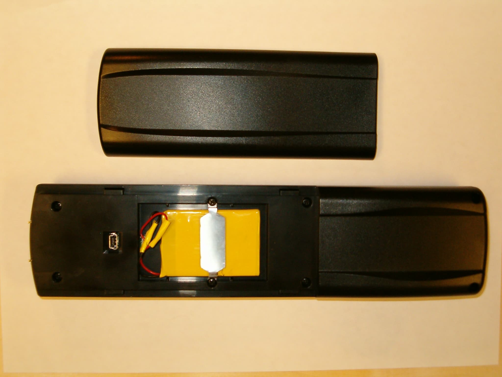
Click to zoom
Application Details
- Equipment Class
- DSR - Part 15 Remote Control/Security Device Transceiver
- Date of Grant
- Sep 19, 2004
- Application Purpose
- Original Equipment
- Date of Application
- Sep 19, 2004
- Equipment Note
- Universal Home Theater Remote Control
- Frequency Range
- 433.82000000 - 433.82000000
- Company
- Remote Technologies Inc
- Country
- United States
Documents & Files
Document Text
Text extracted from the exhibit documents filed with the FCC. Open a document above to read the original.
Users Manual
IR-PRO Professional Infrared Code Capture System Remote Technologies Incorporated Remote Technologies Incorporated Remote Technologies Incorporated Remote Technologies Incorporated 18681 Lake Drive East Chanhassen, MN 55317 Tel: 952-253-3100 Fax: 952-253-3131 www.rticorp.com © 2004 Remote Technologies Inc. All rights reserved. Printed in Taiwan. Itís Under Control Æ IR-PRO Professional Infrared Code Capture System T2+ Universal System Controller T2+ Operation Guide v1.0 i FEDERAL COMMUNICATIONS COMMISSION NOTICE This equipment has been tested and found to comply with the limits for a Class B digital device, pursuant to Part 15 of the FCC Rules. These limits are designed to provide reasonable protection against harmful interference in a residential installation. This equipment generates, uses, and can radiate radio frequency energy and, if not installed and used in accordance with the instructions, may cause harmful interference to radio communications. However, there is no guarantee that interference will not occur in a particular installation. If this equipment does cause harmful interference to radio or television reception, which can be determined by turning the equipment off and on, the user is encouraged to try to correct the interference by one or more of the following measures: • Reorient or relocate the receiving antenna. • Increase the separation between the equipment and the receiver. • Connect the equipment into an outlet on a circuit different from that to which the receiver is connected. • Consult the dealer or an experienced radio/TV technician for help. This device complies with Part 15 of the FCC Rules. Operation is subject to the following two conditions: (1) this device may not cause harmful interference and (2) this device must accept any interference received, including interference that may cause undesired operation. FCC ID: MMURTI0200 CAN: 31661032251 T2+ Universal System Controller ii BATTERY DISPOSAL For environmental reasons, your T2+ universal system controller uses ìenvironmentally soundî Lithium-ion rechargeable batteries. These batteries do not contain any poisonous heavy metals that can damage the environment. In the interest of recycling, please do not dispose of these batteries in the household waste at the end of their useful life. Instead, dispose of them at an appropriate collection site. SAFETY SUGGESTIONS Read Instructions. Read all safety and operating instructions before operating the unit. Heat. Keep the unit away from heat sources such as radiators, heat registers, stoves, etc., including amplifiers that produce heat. Power Sources. Connect the docking station only to the power supply that was included with the unit. Recharge the battery only with the docking station that was included with the unit. Power Cord Protection. Route power supply cords so that they are not likely to be walked on or pinched by items placed on or against them, paying particular attention to the cords at power receptacles and at the point at which they exit from the unit. Nonuse Periods. Unplug the power supply from the outlet when the unit is to be left unused for a long period. Water and Moisture. Do not use the unit near waterófor example, near a sink, in a wet basement, near a swimming pool, near an open window, etc. Object and Liquid Entry. Do not allow objects to fall or liquids to be spilled into the enclosure through openings. Cleaning. The unit should be cleaned only as recommended in the operating guide. Li-ion T2+ Universal System Controller 20 Nominal Run Time on Full Charge 5 hours continuous use (10 - 15 days average use) Standby Time on Full Charge 30 Days Battery Charge Time 3-4 Hours Total System Memory 256K Bytes Flash (non-volatile) Device Capability Total number of devices limited only by memory Macro Capability Up to 64 steps per macro Total number of macros limited only by memory Macros allowed on every button Communications USB programming port Dimensions Length: 9.9 in. (251mm) Width: 2.5 in. (64mm) Height: 1.1 in. (28mm) Enclosure High-impact molded ABS plastic. Weight 8.5 oz. (243g) with battery pack Warranty One Year Parts & Labor (90 days on battery pack) All specifications are subject to change without notice. iii Servicing. Do not attempt any service beyond that described in the operating guide. Refer all other service needs to qualified service personnel. Damage Requiring Service. The unit should be serviced by qualified service personnel when: • The power supply cord or the plug has been damaged. • Objects have fallen or liquid has been spilled into the unit. • The unit does not appear to operate normally or exhibits a marked change in performance. LIMITED WARRANTY Remote Technologies Incorporated warrants its products for a period of one (1) year from the date of purchase from Remote Technologies Incorporated or an authorized Remote Technologies Incorporated distributor. This warranty may be enforced by the original purchaser and subsequent owners during the warranty period, so long as the original dated sales receipt or other proof of warranty coverage is presented when warranty service is required. Except as specified below, this warranty covers all defects in material and workmanship in this product. The following are not covered by the warranty: Damage resulting from: 1. Accident, misuse, abuse, or neglect. 2. Failure to follow instructions contained in this Guide. 3. Repair or attempted repair by anyone other than Remote Technologies Incorporated. 4. Causes other than product defects, including lack of skill, competence or experience of user. 5. Shipment of this product (claims must be made to carrier). 6. Being altered or which the serial number has been defaced, modified or removed. T2+ Universal System Controller iv Remote Technologies Incorporated is not liable for any damages caused by its products or for its failure of its products to perform, including any lost profits, lost savings, incidental damages, or consequential damages.…
Text truncated - open the document above for the full version.
Block Diagram
Remote Technologies Incorporated TheaterTouch System Controller RF Block/Signal Diagram 433 MHz SAW Vcc 50 Ohm R F Out Oscillator (Ant.) 300-5000 BPS 01- 2 8- 2 0 00 Data In Keyed Output Output Isolation RF Amplifier and Filter Remote Technologies Incorporated TheaterTouch System Controller Block/Signal Diagram 433 MHz RF Dau g hterbo ard LCD Disp l ay MCU (uPSD3234 ) Linx Splatch Antenna Linx RF Transmitter 433Mhz 36M h z Oscilla to r Neg a tive Contrast Supp l y Voltage Inverter (Backlight) VCC Supp l y Battery Keypad
Operational Description
Remote Technologies Incorporated •7630 Executive Dr. • Eden Prairie, MN 55344 • Tel. 612.937.2600 • Fax 612.937.7527 Universal System Controller Operational Description Purpose of the TheaterTouch The intended use of the Universal System Controller is to transmit IR, (infrared) control signals to home electronic devices. These devices include VCRs, DVD players, TV cable boxes, audio surround decoders, satellite receivers, televisions, etc. The Universal System Controller is a custom programmable device that contains a touchscreen display and keypad buttons. The Touchscreen display and keypad are programmed with the users set of electronic equipment and the parameters that can be controlled. The user interface on the touchscreen display is also custom programmable. The Universal System Controller is then programmed with the IR controls for each electronic device that the user desires to use. Universal System Controller Transmitter When the user interface for the electronic devices to be controlled and the IR control signals have been programmed into the Universal System Controller it is ready to use. When a user presses on the touchscreen or keypad to transmit, for example to start the play control on a VCR, the microprocessor, uPSD3234, senses the push. The IR control signal corresponding to that location on the touchscreen or keypad is then pulled from internal FLASH memory. When the IR control signal is identified, the control signal is routed to the RF transmitter board. The control signal is modulated on the RF transmitter board and output. All timing is derived from a 36MHz crystal and 433MHz SAW oscillator. TheaterTouch Antenna The antenna on the Universal System Controller is a grounded line SMD Planar (Splatch), soldered to the RF module, internal to the chassis and is not easily accessible.
Schematics
55 44 33 22 11 D D C C B B A A FOR EL B.L. NOISE SUPPRESION T22 Main BoardRemote Tec hnologies Incorporated Tuesday, J une 01, 2004 14 C 18681 Lake Drive EastChanhassen, MN 55317 D6 30-210064-20-18 T22 JMD SizeScale CAGE Code DWG NO Rev Sheet of DateDateDateDate Model Title DFTGCHKDMFGAPPVLPage Modify Date THIS IS AN UNPUBLISHED WORK CONTAINING REMOTETECHNOLOGIES INCORPORATED CONFIDENTIAL ANDPROPRIETARY INFORMATION. DISCLOSURE, USE ORREPRODUCTION WITHOUT THE WRITTEN AUTHORIZATIONOF REMOTE TECHNOLOGIES IS STRICTLY PROHIBITED. VBATTGNDVCC TDOTCKTMS/RSTTDI GNDVCC VBATT ROW 5 PWM CARRIERBACKLIGHT ENABLE DB7 RF DI RF DO BEEPER DB4 RF /RESET LCD D/I DB1 RF /CTS RF SLEEP PWM CARRIER ROW 2 COL 7 /LCD CS1 VBATT KEY INT ROW 6 CONTRAST ADJ DB6 COL 6 V_LCD_E DB3 ROW 1 DB0 /RST COL 4COL 3 ROW 7 LCD E RF STATUS RF RSSI ROW 4 CONTRAST CTRL DB5 COL 2COL 1 KEY INT COL 5 DB2 RF /RTS ROW 3 TILT SWITCH /LCD CS2 IR OUT /LOW BAT VCC VCC V_BUS V_BUS VCC VCC VCC R6010K R5110K R5810K U1 uPSD3234 123 4 56789 10 1213 141516 1819 20 2122232425262728 29 30313233343536373839 40 41 42 4344454647 4849 50 51 52 53 54 55 56 5758 596061 6263 64 656667 68 69 70 727374 75 767778 79 80 PD2P3.3/INT1PD1 ALE/PD0 PC7PC6PC5USB_D-PC4USB_D+ VCC_1GND_1 PC3PC2PC1 PWM4/P4.7PWM3/P4.6 PC0 PA7PA6 PWM2/P4.5 PA5 PWM1/P4.4 PA4 PWM0/P4.3 PA3 GND_2 VSYNC/P4.2 DSCL/P4.1 PA2 DSDA/P4.0 PA1PA0 AD0/P0.0AD1/P0.1AD2/P0.2 AD3/PO.3 P3.4/T0 AD4/P0.4 T1/P3.5 AD5/P0.5 ISDA/P3.6 AD6/P0.6 ISCL/P3.7 AD7/P0.7 XTAL_1XTAL_2 VCC_2 A8/P2.0 CNT2/P1.0 A9/P2.1 TRG2/P1.1 A10/P2.2 P1.2/RXD1 A11/P2.3 TXD1/P1.3 P1.4/ADC0P1.5/ADC1P1.6/ADC2 WR/CTRL0 PSEN/CTRL2 P1.7/ADC3 RD/CTRL1 PB7PB6 RESET GND_3 VREF PB5PB4PB3 P3.0/RXD PB2 TXD/P3.1 PB1 P3.2/INT0 PB0 R5410K U24.60VMicrochipMCP120-460 1 2 RESET VCC R756K R5910K U14SN75240 1 3 5 72 4 6 8 C61.0 uF 1 2 R5510K R256K U13 MM74VHC541 1 19 23456789 1817161514131211 OE1 OE2A0A1A2A3A4A5A6A7 Y0Y1Y2Y3Y4Y5Y6Y7 R8 100 R556K R9 100 C70.1 uF Y1 36 MHz R5610K R156K C527 pF J2 Mini USB Connector 15 23 VBUSGND D- D+ R656K R5210K R107.5K J1 CON9 123456789 C4 27 pF C10.1 uF C8 0.1 uF C20.1 uF C30.1 uF R5710K R5310K 55 44 33 22 11 D D C C B B A A CURSOR DN 9 2 GUIDE BACKLIGHT 6 1 CHAN DOWN 5 VOLUME DN 0 EXIT (Heat sink Drain withcopper around part) MERCURY SWITCH POWER SELECT MAIN MENU * 7 FOR TOUCH PANEL CURSOR UP MUTE 8 CHAN UP CURSOR RT 4 VOL UP RF TRANSCEIVER CONNECTIONS CURSOR LT 3 ENTER PAUSE PLAY SKIP >| SCAN >> STOP << SCAN T22 Main BoardRemote Tec hnologies Incorporated Tuesday, J une 01, 2004 24 C 18681 Lake Drive EastChanhassen, MN 55317 D6 30-210064-20-18 T22 JMD SizeScale CAGE Code DWG NO Rev Sheet of DateDateDateDate Model Title DFTGCHKDMFGAPPVLPage Modify Date THIS IS AN UNPUBLISHED WORK CONTAINING REMOTETECHNOLOGIES INCORPORATED CONFIDENTIAL ANDPROPRIETARY INFORMATION. DISCLOSURE, USE ORREPRODUCTION WITHOUT THE WRITTEN AUTHORIZATIONOF REMOTE TECHNOLOGIES IS STRICTLY PROHIBITED. VBATTGNDVCC ROW 1ROW 6ROW 2ROW 5ROW 4ROW 3ROW 7 GNDVCC VBATT ROW 4ROW 1 RF /RTSRF DI RF /CTS COL 5 RF DO RF /RESET ROW 6ROW 3 RF SLEEP TILT SWITCH ROW 2 COL 1COL 2 BEEPER ROW 7 COL 3 RF STATUS ROW 5 COL 6 COL 4 IR OUT VBATT RF RSSI COL 7 VCC VCC VCC VCC SW26 1 2 + C9 47 uF10 VDC 1 2 R500 C111.0 uF 1 2 R182.0K SW23 1 2 + C10 47 uF10 VDC 1 2 IRLED2LN68 SW19 1 2 SW30 1 2 SW15 1 2 R2010K SW4 1 2 J4 CON4 1234 SW8 1 2 SW1 1 2 C140.1 uF 1 2 SW5 1 2 R762.0K SW9 1 2 SW31 1 2 R1556K R7456K 12 SW12 1 2 Q1 Zetex Inc.ZXM61N02F D G S SW16 1 2 IRLED1LN68 SW20 1 2 Q2 Zetex Inc.ZXM61N02F D G S R110.5, 1/4W SW24 1 2 R7210K R172.0K SW28 1 2 SW2 1 2 S1 3004 1 2 SW6 1 2 R192.0K SW10 1 2 SW13 1 2 D41N5817 AK SW17 1 2 R13 0 SW21 1 2 SW25 1 2 R2110K SW3 1 2 R162.0K SW33 1 2 C120.1 uF SW7 1 2 R1456K BZ1 SMT-917 - + SW29 1 2 SW11 1 2 J5 MOLEX 52271-0990 123456789 Q5 Zetex Inc.ZXM61N02F D G S R1256K SW14 1 2 C130.01uF R7310K R7556K 12 SW32 1 2 SW18 1 2 SW22 1 2 J3 CON11 1234567891011 SW27 1 2 55 44 33 22 11 D D C C B B A A Contacts for LCD Glass DNP T22 Main Board Remote Technologies Incorporated Tuesday, J une 01, 2004 34 C 18681 Lake Drive EastChanhassen, MN 55317 D6 30-210064-20-18 T22 JMD SizeScale CAGE Code DWG NO Rev Sheet of DateDateDateDate Model Title DFTGCHKDMFGAPPVLPage Modify Date THIS IS AN UNPUBLISHED WORK CONTAINING REMOTETECHNOLOGIES INCORPORATED CONFIDENTIAL ANDPROPRIETARY INFORMATION. DISCLOSURE, USE ORREPRODUCTION WITHOUT THE WRITTEN AUTHORIZATIONOF REMOTE TECHNOLOGIES IS STRICTLY PROHIBITED. V_LCDGNDVCC COM 38COM 47SEG 89SEG 72SEG 23 SEG 118SEG 49COM 32 COM 51 COM 11 SEG 9SEG 13SEG 82SEG 65 SEG 128SEG 59SEG 42COM 25 SEG 11COM 42SEG 92SEG 75SEG 26 SEG 101SEG 52SEG 35 COM 44SEG 85COM 52SEG 68 SEG 111SEG 62SEG 45COM 14 SEG 95SEG 78 SEG 121COM 18SEG 104SEG 55 SEG 4COM 57SEG 88SEG 19 SEG 114COM 28 COM 59 SEG 97 SEG 2SEG 14SEG 29 COM 5SEG 124SEG 107SEG 38COM 21 COM 60SEG 10SEG 7 COM 8 SEG 71SEG 22 COM 31SEG 117SEG 48 COM 62SEG 6 COM 4 SEG 81SEG 32 SEG 127SEG 58SEG 41COM 24 SEG 5COM 41SEG 91SEG 74SEG 25 SEG 100SEG 51SEG 34COM 6 SEG 8SEG 16 COM 10 SEG 84SEG 67 SEG 110 COM 63 SEG 61SEG 44 COM 39COM 35 COM 13 SEG 94SEG 77 SEG 120SEG 103COM 17SEG 54 COM 46SEG 87SEG 18 COM 27 COM 54 SEG 113SEG 64COM 16 SEG 15SEG 28 SEG 123SEG 37COM 20 COM 53 SEG 106 COM 40SEG 70SEG 21 SEG 116SEG 47COM 30 COM 58COM 43SEG 80SEG 31 SEG 126SEG 57SEG 40COM 23 COM 55SEG 1SEG 3SEG 90SEG 73SEG 24 SEG 99SEG 33COM 12SEG 50 COM 64COM 48 COM 7COM 3 SEG 12SEG 83SEG 66 SEG 109SEG 60SEG 43COM 26 COM 33COM 45SEG 93SEG 76 SEG 119SEG 102SEG 53SEG 36COM 1 COM 37SEG 86SEG 17 SEG 112 COM 56 COM 15SEG 63SEG 46COM 9 SEG 96SEG 27 SEG 122SEG 105COM 19 COM 50 SEG 56COM 2 COM 34SEG 69SEG 20 COM 29SEG 115SEG 98 COM 61COM 36SEG 79SEG 30 SEG 125SEG 39COM 22 COM 49 SEG 108 GNDVCC V_LCD COM 56 SEG 62 LCD D/I SEG 93 SEG 74SEG 10 LCD D/I V5 COM 20 SEG 35 COM 30 COM 19 SEG 24 SEG 20 COM 23 CL V4 COM 63 SEG 108 SEG 116 COM 64 COM 38 SEG 127 SEG 2 V0 COM 58 SEG 23SEG 95 LCD R/W COM 25 SEG 88 SEG 113 SEG 112 SEG 122 SEG 31 CLK1 COM 34 SEG 59 SEG 34 LCD E DB4 V5 CL SEG 70 VOP COM 31 COM 13 SEG 25 /LCD CS2 COM 40 SEG 104 COM 46…
Text truncated - open the document above for the full version.
Test Report
TEST REPORT Report Number: 3060676.011 Project Number: 3060676 September 13, 2004 Evaluation of the Sonance ST2 Remote Control Transmitter FCC ID: Canada IC ID: For Sonance Test Performed by: Test Authorized by: Intertek 7250 Hudson Blvd. Suite 100 Oakdale, MN 55128 Sonance 212 Avendia Fabricante San Clemente, CA 92672 Prepared by: Date: September 13, 2004 Uri Spector Approved by: Date: September 13, 2004 Norman Shpilsher Intertek ETL SEMKO 7250 Hudson Boulevard, Suite 100, Oakdale, MN 51228 Telephone 651-730-1188, Fax 651-730-1282 Home Page www.intertek.com CONTENTS 1.0 GENERAL DESCRIPTION ....................................................................................................... 1 1.1 Related Submittals Grants................................................................................................................ 1 1.2 Product Description ......................................................................................................................... 1 1.3 Test Methodology ............................................................................................................................ 1 1.4 Test Facility ..................................................................................................................................... 1 2.0 SYSTEM TEST CONFIGURATION....................................................................................... 2 2.1 Justification ...................................................................................................................................... 2 2.2 EUT Setup........................................................................................................................................ 2 2.3 EUT Exercising Software ................................................................................................................ 2 2.4 Special Accessories.......................................................................................................................... 2 2.5 Equipment Modification .................................................................................................................. 2 2.6 Support Equipment List and Description.........................................................................................2 2.7 Test Configuration Block Diagrams ................................................................................................ 3 3.0 TEST RESULTS ........................................................................................................................... 4 3.1 Transmitting Time, FCC 15.231(a)(1) .............................................................................................5 3.2 Field Strength of Fundamental and Spurious Emissions, FCC 15.231(b) ....................................... 6 3.3 Bandwidth of Emissions, FCC 15.231(c) ...................................................................................... 11 3.4 Radiated Emissions, FCC 15.109, Class B (ST2 remote control transmitter) ............................... 13 3.4.1 Radiated Emissions, FCC 15.109 & Line Conducted Emissions, FCC 15.107, Class B (ST2 remote control charger) ................................................................................................................ 14 3.5 Test Procedure ............................................................................................................................... 17 3.6 Field Strength Calculation ............................................................................................................. 18 4.0 TEST EQUIPMENT.................................................................................................................. 19 IC ID: MMURTI0200 September 2004 Page 1 of 19 1.0 GENERAL DESCRIPTION 1.1 Related Submittals Grants This is single application of the Sonance ST2 Remote Control Transmitter for Certification under FCC Part 15, Subpart C. There are no other simultaneous applications. The Receiver portion will be verified under Declaration of Conformity. 1.2 Product Description ST2 Remote Control Transmitter is a RF remote control operating in 433.82MHz. The intended use of the ST2 Remote Control Transmitter is to generate and transmit a RF signal to control window opener. The ST2 Remote Control Transmitter powered at 4.2VDC from Lithium internal rechargeable battery. Antenna Description: Integrated antenna Sample Submitted: June 11, 2004 Test Work Started: June 11, 2004 Test Work Completed: September 13, 2004 1.3 Test Methodology Emission measurements were performed according to the procedures in ANSI C63.4-2000. All field strength radiated emissions measurements were performed in the semi-anechoic chamber, and for each scan, the procedure for maximizing emissions in Appendices D and E were followed. All field strength radiated tests were performed at an antenna to EUT distance of 3 meters, unless stated otherwise in the "Justification Section" of this Application. 1.4 Test Facility The test site facility used to collect the radiated and conducted measurement data is located at 7250 Hudson Blvd., Suite 100, Oakdale, Minnesota. This test facility has been fully described in a report dated on March 2003 submitted to FCC. Please reference the site registration number: 90706, dated April 18, 2003. IC ID: MMURTI0200 September 2004 Page 2 of 19 2.0 SYSTEM TEST CONFIGURATION 2.1 Justification N/A 2.2 EUT Setup For simplicity of testing, the transmitter was wired to transmit continuously 2.3 EUT Exercising Software N/A 2.4 Special Accessories Sonance battery charger using HON-KWANG AC Adapter model: HK-CH03-A06. USB port. Note: According to the manufacturers’ specification, the ST2 remote control transmitter will not operate while it is connected to a PC’s USB port. In addition, the ST2 will not be able to sync with a PC’s USB port while it is transmitting a command. The USB port is only used to download software (by an RTI dealer). Therefore, USB cable was not…
Text truncated - open the document above for the full version.
Test Setup Photos
Radiated Emissions Test Configuration (ST2 Remote Control Transmitter) Radiated Emissions Test Configuration (ST2 Remote Control Transmitter) Radiated Emissions Test Configuration (ST2 Remote Control Charger) Radiated Emissions Test Configuration (ST2 Remote Control Charger) Line Conducted Emissions Test Configuration (ST2 Remote Control Charger) Line Conducted Emissions Test Configuration (ST2 Remote Control Charger)
Contact Information
Applicant
John Demskie(President)
Technical Contact
IntertekYuriy Litvinov
[email protected]651-730-1188
7250 Hudson Blvd. · Oakdale, Minnesota · United States
Non-Technical Contact
Remote Technologies Inc.Paul Weichelt
[email protected]952-253-3100
Test Firm
Intertek Testing ServicesUri Spector
Technical Specifications
| # | Rule Parts | Frequency Range | Power Output |
|---|---|---|---|
| 1 | 15.231 | 433.82 MHz - 433.82 MHz | - |
Other Applications from Remote Technologies Inc
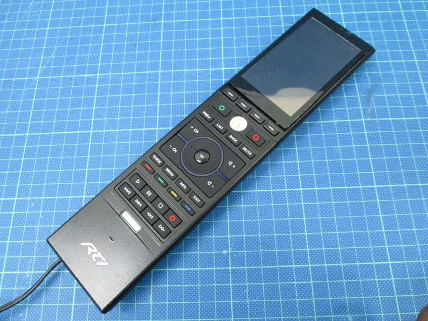
MMURTI2100
Mar 25, 2015APM 6998 WiFi Module
Equipment Class
DTS - Digital Transmission System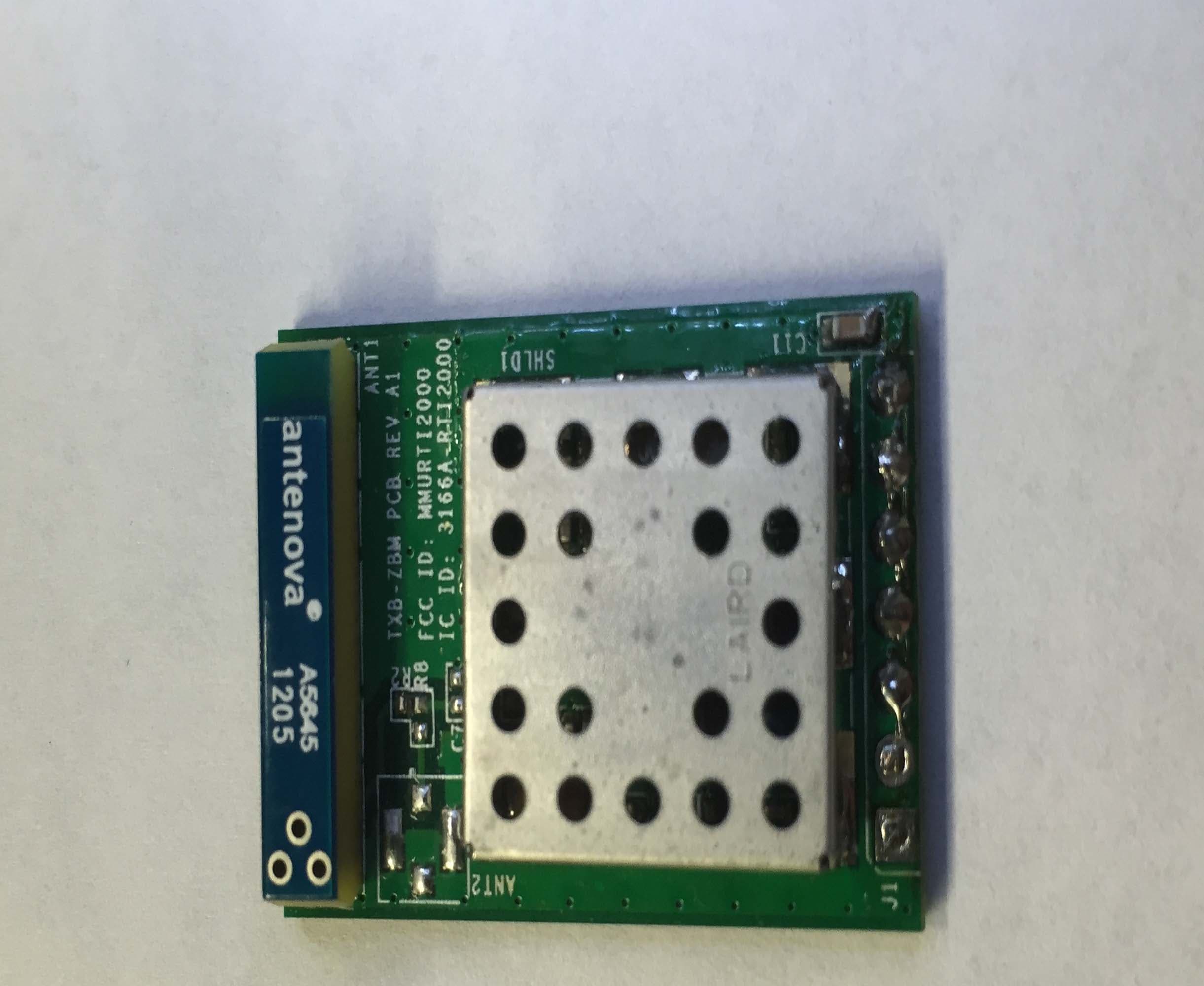
MMURTI2000
Feb 16, 2015TXB-ZBM
Equipment Class
DTS - Digital Transmission System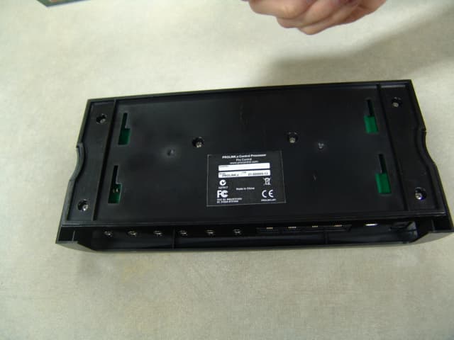
MMURTI1800
Jun 01, 2011ProLink.z Control Processor
Equipment Class
DXX - Part 15 Low Power Communication Device Transmitter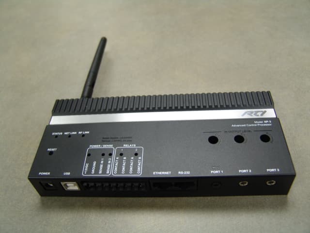
MMURTI1900
May 23, 2011Advanced Control Processor
Equipment Class
DXT - Part 15 Low Power Transceiver, Rx Verified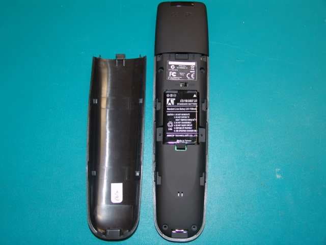
MMURTI1700
Mar 31, 2011Remote Controller
Equipment Class
DSC - Part 15 Security/Remote Control Transmitter