MMURTI2100APM 6998 WiFi Module
Remote Technologies Inc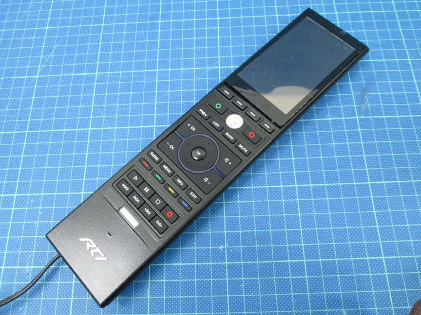
Click to zoom
Application Details
- Equipment Class
- DTS - Digital Transmission System
- Date of Grant
- Mar 25, 2015
- Application Purpose
- Original Equipment
- Date of Application
- Mar 25, 2015
- Equipment Note
- APM 6998 WiFi Module
- Frequency Range
- 2412.00000000 - 2462.00000000
- Company
- Remote Technologies Inc
- Country
- United States
Documents & Files
Document Text
Text extracted from the exhibit documents filed with the FCC. Open a document above to read the original.
Users Manual
APM 6998 WiFi Module Manual Host Revision Information Host Hardware Revision T3x Rev D1 Host‐Module Driver Version v8.1.4.4 Module Hardware Revision 001E Host PCB Design Guidelines The following guidelines must be followed when designing a host board that incorporates the APM 6998 WiFi Module (“module”). Host PCB Guidelines 1. The +3.3VDC power rail must be supplied by a DC/DC regulator. 2. The +1.8VDC power rail must be supplied by a DC/DC regulator. 3. A 0.050” x 0.050” ground via stitching around the front end, including antenna trace, antenna cutout and PCB edge to which the antenna is near. 4. No traces underneath the module on the same layer that the module is installed on. 5. A solid ground pour underneath the module and surrounding the front‐end on the same layer that the module is installed on. 6. High Temp FR4 94V‐0 IPC4101A PCB material with a dielectric constant of 4.8 and a loss tangent of 0.016 shall be used. Antenna Guidelines 1. The antenna used must be of equal or lesser gain than the Pulse W3008C used in the original module certification, which is +2.2dBi. 2. In the case of using the Pulse W3008C: a. The antenna must be placed on a PCB edge. b. The antenna must be placed a minimum distance of 10mm from the corner of the PCB. c. If the antenna is not placed on a PCB edge equidistant from either end, the antenna feed shall be from the “inside” of the PCB, i.e. the longer side. d. The PCB guidelines for antenna layout referenced in the document “Pulse W3008C Guidelines.pdf” must be followed. Installation Instructions When the module is installed in an RTI product it is permanently affixed to the host product and cannot be removed without the use of additional equipment. This module is also not visible, nor accessible by the end‐user. Any attempted access or removal of the module by anyone other than RTI or its authorized Contract Manufacturers is strictly prohibited. Any RTI host containing the module must adhere to RTI’s strict host PCB guidelines as outlined above in order to remain compliant. Purpose of the APM 6998 WiFi Module The APM 6998 WiFi Module (“module”) is a module that can be installed in applicable Remote Technologies Inc. (“RTI”) products only. This module is not sold retail by RTI, nor is it provided by RTI as an OEM product to other manufacturers or companies for installation into their products. RTI and its authorized Contract Manufacturers are the only authorized installers of this module and it is not provided as a field or end‐user upgrade. When properly and permanently installed in an applicable RTI product, the module will provide 2.4GHz 802.11b/g/n communication with other WiFi enabled devices. This photo includes the Module and Host. Antenna trace Federal Communication Commission Interference Statement The Operation Manual of the host RTI product will display the following information in accordance with FCC guidelines: Contains FCC ID: MMURTI2100 Any changes or modifications not expressly approved by the party responsible for compliance could void the user’s authority to operate the device. This device complies with Part 15 of the FCC Rules. Operation is subject to the following two conditions: 1. This device may not cause harmful interference. 2. This device must accept any interference received, including interference that may cause undesired operation. This equipment has been tested and found to comply with the limits for a Class B digital device, pursuant to part 15 of the FCC Rules. These limits are designed to provide reasonable protection against harmful interference in a residential installation. This equipment generates uses and can radiate radio frequency energy and, if not installed and used in accordance with the instructions, may cause harmful interference to radio communications. However, there is no guarantee that interference will not occur in a particular installation. If this equipment does cause harmful interference to radio or television reception, which can be determined by turning the equipment off and on, the user is encouraged to try to correct the interference by one or more of the following measures: —Reorient or relocate the receiving antenna. —Increase the separation between the equipment and receiver. —Connect the equipment into an outlet on a circuit different from that to which the receiver is connected. —Consult the dealer or an experienced radio/TV technician for help. FCC Radiation Exposure Notice ‐To comply with FCC RF exposure compliance requirements, a separation distance of at least 20 cm must be maintained between the antenna of this device and all persons. ‐This Transmitter must not be co‐located or operating in conjunction with any other antenna or transmitter Labeling of the end product When the module is installed in the host device, the FCC ID/ IC label must be visible through a window on the final device or it must be visible when an access panel, door or cover is easily re‐ moved. If not, a second label must be placed on the outside of the final device that contains the following text: “Contains FCC ID: MMURTI2100” Industry Canada Statement The Operation Manual of the host RTI product will display the following information in accordance with Industry Canada RSS standard(s): Contains IC: 3166A‐RTI2100 This device complies with Industry Canada License‐exempt RSS standard(s). Operation is subject to the following two conditions: 1. This device may not cause harmful interference. 2. This device must accept any interference received, including interference that may cause undesired operation. Le présent appareil est conforme aux CNR d'Industrie Canada applicables aux appareils radio exempts de licence. L'exploitation est autorisée aux deux conditions suivantes: 1. l'appareil ne doit pas produire de brouillage 2. l'appareil doit accepter tout brouillage radioélectrique subi, même si le brouillage est susceptible d'en compromettre le fonctionnement. IC Radiation Exposure Notice IC RF Radiation Exposure Stateme…
Text truncated - open the document above for the full version.
External Photos
External photo of EUT External photo of EUT External photo of EUT
ID Label/Location Info
Label location
Internal Photos
Internal photo of EUT 1 The photos of EUT Host-Module Driver Version:v8.1.4.4 Module Hardware Revision:001E 1 cm Internal photo of EUT 2 Internal photo of EUT 3 The photos of the specific host Host Hardware Revision: T3x Rev D1 Host-Module Driver Version: v8.1.4.4 Module Hardware Revision:001E Internal photo of EUT 4 Antenna Internal photo of EUT 5 The side view of RF shielding Internal photo of EUT 6 The side view of RF shielding Internal photo of EUT 7 RF Module Antenna trace Internal photo of EUT 8 Internal photo of EUT 9 Internal photo of EUT 10 Internal photo of EUT 11 Internal photo of EUT 12 Internal photo of EUT 13 Internal photo of EUT 14 Internal photo of EUT 15 Internal photo of EUT 16 Internal photo of EUT 17 AC Adapter (Peripheral) Internal photo of EUT 18
RF Exposure Info
FCC ID: MMURTI2100 Report No.: 141200113TWN-001 Page 1 of 12 0597 Maximum Permissible Exposure (MPE) Evaluation Report Report No. : 141200112TWN-001 Model No. : APM 6998 WiFi Module Issued Date : Feb. 25, 2015 Applicant: Remote Technologies Incorporated 5775 12th Avenue East, Suite 180, Shakopee, MN 55379 USA Test Method/ Standard: FCC 1.1310 Test By: Intertek Testing Services Taiwan Ltd. No. 11, Lane 275, Ko-Nan 1 Street, Chia-Tung Li, Shiang-Shan District, Hsinchu City, Taiwan It may be duplicated completely for legal use with the allowance of the applicant. It shall not be reproduced except in full, without the written approval of Intertek Laboratory. The test result(s) in this report only applies to the tested sample(s). The test report was prepared by: Evelyn Lee/ Officer These measurements were taken by: Wayne Chen/ Engineer The test report was reviewed by: Name Jimmy Yang Title Senior Engineer FCC ID: MMURTI2100 Report No.: 141200113TWN-001 Page 2 of 12 Table of Contents Summary of Tests ..............................................................................................................3 1. General information ......................................................................................................4 1.1 Identification of the EUT ........................................................................................4 1.2 Antenna description.................................................................................................5 1.3 Additional information of Host and Module ...........................................................5 1.4 Peripherals equipment .............................................................................................5 2. Test specifications .........................................................................................................6 2.1 Introduction .............................................................................................................6 2.2 RF Exposure Limit ..................................................................................................7 2.3 RF Exposure calculations........................................................................................9 2.4 Operation mode .......................................................................................................9 2.5 Test equipment ......................................................................................................10 2.6 Test Set-up .............................................................................................................11 3. Test results ...................................................................................................................12 FCC ID: MMURTI2100 Report No.: 141200113TWN-001 Page 3 of 12 Summary of Tests MPE Evaluation meet FCC OET No. 65: 1997, IEEE C95.1-2005 Test Reference Results MPE Evaluation FCC Guidelines for Human Exposure IEEE C95.1Complies FCC ID: MMURTI2100 Report No.: 141200113TWN-001 Page 4 of 12 1. General information 1.1 Identification of the EUT Product: APM 6998 WiFi Module Model No: APM 6998 WiFi Module FCC ID: MMURTI2100 Operating Frequency: 2412 MHz ~ 2462 MHz for 802.11b, 802.11g, 802.11n (HT20) Channel Number: 11 channels for 2412 MHz ~ 2462 MHz Access scheme: DSSS, OFDM Rated Power: DC 1.8 and 3.3V from HOST Power Cord: N/A Sample Received: Dec. 10, 2014 Sample condition: Workable Test Date(s): Dec. 23, 2014 ~ Feb. 25, 2015 Note 1: This report is for the exclusive use of Intertek's Client and is provided pursuant to the agreement between Intertek and its Client. Intertek's responsibility and liability are limited to the terms and conditions of the agreement. Intertek assumes no liability to any party, other than to the Client in accordance with the agreement, for any loss, expense or damage occasioned by the use of this report. Only the Client is authorized to permit copying or distribution of this report and then only in its entirety. Any use of the Intertek name or one of its marks for the sale or advertisement of the tested material, product or service must first be approved in writing by Intertek. The observations and test results in this report are relevant only to the sample tested. This report by itself does not imply that the material, product, or service is or has ever been under an Intertek certification program. Note 2: When determining the test conclusion, the Measurement Uncertainty of test has been considered. FCC ID: MMURTI2100 Report No.: 141200113TWN-001 Page 5 of 12 1.2 Antenna description The antenna is affixed to the EUT using a unique connector, which allows for replacement of a broken antenna, but DOES NOT use a standard antenna jack or electrical connector. Antenna Gain : 2.2 dBi max Antenna Type : Chip antenna Connector Type : Fixed 1.3 Additional information of Host and Module The model of the host: T3x Host Hardware Revision: T3x Rev D1 Host Module Driver Version: v8.1.4.4 Module Hardware Revision: 001E 1.4 Peripherals equipment Peripherals Brand Model No. Serial No. Data cable Adapter N/A KTPS05-03315UN/A N/A Host RTI T3x N/A N/A FCC ID: MMURTI2100 Report No.: 141200113TWN-001 Page 6 of 12 2. Test specifications 2.1 Introduction The EUT operates in the 2.4 GHz ISM band. Due to the EUT (include antenna) at its normal operation distance is at least 20 cm from the human body, the EUT was defined as a Mobile Device. The reason to do the MPE Evaluation is to avoid the RF hazard to human body. The maximum output power and gain of the antenna were used to calculate the limited Power density (S) at 20 cm distance away from the product. The limit for Maximum Permissible Exposure (MPE) specified in FCC 1.1310 and Safety Code 6 are followed. According to 1.1307 (b)(1), systems operating under the provisions of this section shall be operated in a manner that ensure that the public is not exposed to radio frequency energy level in excess of the Commission’s guideline. FCC ID: MMURTI2100 Report No.: …
Text truncated - open the document above for the full version.
Test Report
FCC ID: MMURTI2100 Report No.: 141200112TWN-001 Page 1 of 51 EMC TEST REPORT Report No. : 141200112TWN-001 Model No. : APM 6998 WiFi Module Issued Date : Apr. 11, 2015 Applicant: Remote Technologies Incorporated 5775 12th Avenue East, Suite 180, Shakopee, MN 55379 USA Test Method/ Standard: 47 CFR FCC Part 15.247 & ANSI C63.4 2003 KDB 558074 D01 v03r02 Test Site : 93910 Test By: Intertek Testing Services Taiwan Ltd. No. 11, Lane 275, Ko-Nan 1 Street, Chia-Tung Li, Shiang-Shan District, Hsinchu City, Taiwan It may be duplicated completely for legal use with the allowance of the applicant. It shall not be reproduced except in full, without the written approval of Intertek Laboratory. The test result(s) in this report only applies to the tested sample(s). The test report was prepared by: Evelyn Lee/ Officer These measurements were taken by: Wayne Chen/ Engineer The test report was reviewed by: Name Jimmy Yang Title Senior Engineer FCC ID: MMURTI2100 Report No.: 141200112TWN-001 Page 2 of 51 Table of Contents 1. Summary of Test Data............................................................................................................... 4 2. General Information .................................................................................................................. 5 2.1 Identification of the EUT...................................................................................................... 5 2.2 Description of EUT .............................................................................................................. 6 2.3 Antenna description ............................................................................................................ 6 2.4 Additional information.......................................................................................................... 6 2.5 Peripherals equipment ........................................................................................................ 6 2.6 Operation mode .................................................................................................................. 7 2.7 Applied test modes and channels ....................................................................................... 8 2.8 Power setting of test software .............................................................................................9 3. Minimum 6 dB Bandwidth ....................................................................................................... 10 3.1 Operating environment ..................................................................................................... 10 3.2 Limit for minimum 6dB bandwidth ..................................................................................... 10 3.3 Measuring instrument setting ............................................................................................ 10 3.4 Test procedure .................................................................................................................. 10 3.5 Test diagram...................................................................................................................... 11 3.6 Test results ........................................................................................................................ 11 4. Maximum Peak Conducted Output Power .............................................................................. 17 4.1 Operating environment ..................................................................................................... 17 4.2 Limit for maximum peak conducted output power............................................................. 17 4.3 Measuring instrument setting ............................................................................................ 17 4.4 Test procedure .................................................................................................................. 17 4.5 Test diagram...................................................................................................................... 17 4.6 Test result.......................................................................................................................... 18 5. Power Spectral Density........................................................................................................... 19 5.1 Operating environment ..................................................................................................... 19 5.2 Limit for power spectrum density ...................................................................................... 19 5.3 Measuring instrument setting ............................................................................................ 19 5.4 Test procedure .................................................................................................................. 20 5.5 Test diagram...................................................................................................................... 20 5.6 Test results ........................................................................................................................ 20 FCC ID: MMURTI2100 Report No.: 141200112TWN-001 Page 3 of 51 6. Emissions In Non-Restricted Frequency Bands ..................................................................... 26 6.1 Operating environment ..................................................................................................... 26 6.2 Limit for emissions in non-restricted frequency bands ...................................................... 26 6.3 Measuring instruments setting .......................................................................................... 26 6.4 Test procedure .................................................................................................................. 27 6.5 Test diagram...................................................................................................................... 27 6.6 Test results .....…
Text truncated - open the document above for the full version.
Test Setup Photos
Conducted Emission Test set-up photo Radiated Emission Test set-up photo Radiated Emission Radiated Emission Test set-up photo
Contact Information
Applicant
John Demskie(President)
Test Firm
Intertek Testing Services Taiwan Ltd.Lily Shih
Technical Specifications
| # | Rule Parts | Frequency Range | Power Output |
|---|---|---|---|
| 1 | 15C | 2.41 GHz - 2.46 GHz | 98.17 mW |
Other Applications from Remote Technologies Inc
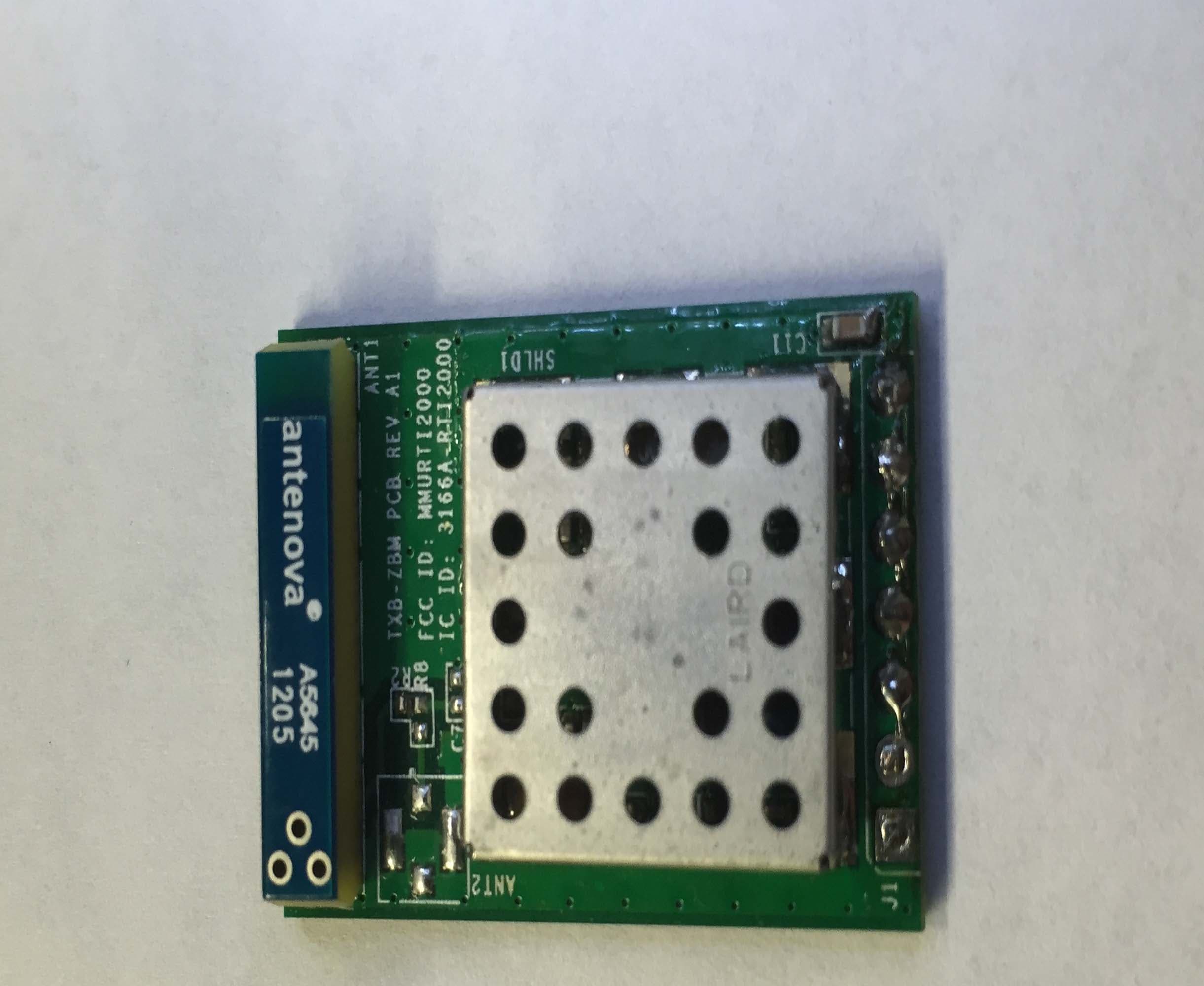
MMURTI2000
Feb 16, 2015TXB-ZBM
Equipment Class
DTS - Digital Transmission System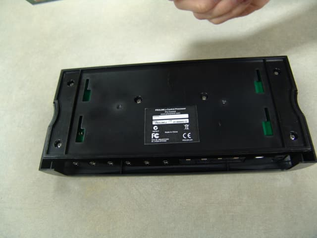
MMURTI1800
Jun 01, 2011ProLink.z Control Processor
Equipment Class
DXX - Part 15 Low Power Communication Device Transmitter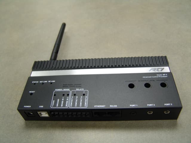
MMURTI1900
May 23, 2011Advanced Control Processor
Equipment Class
DXT - Part 15 Low Power Transceiver, Rx Verified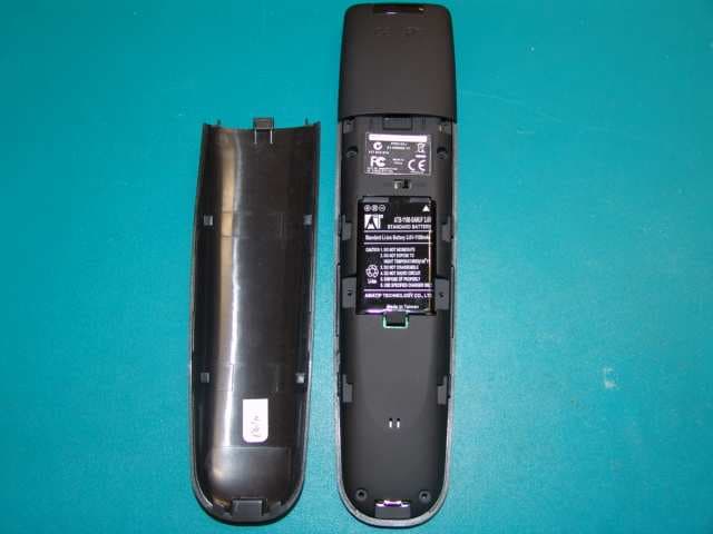
MMURTI1700
Mar 31, 2011Remote Controller
Equipment Class
DSC - Part 15 Security/Remote Control Transmitter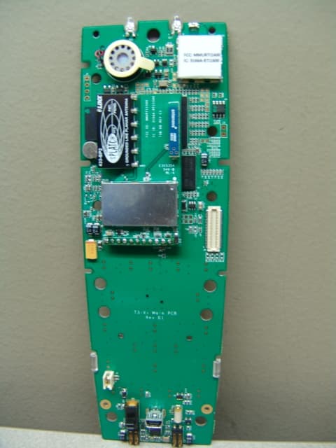
MMURTI1600
Dec 09, 2010W2SW0001 RF Module
Equipment Class
DTS - Digital Transmission System