MMURTI0600T2-C Universal System Controller
Remote Technologies Inc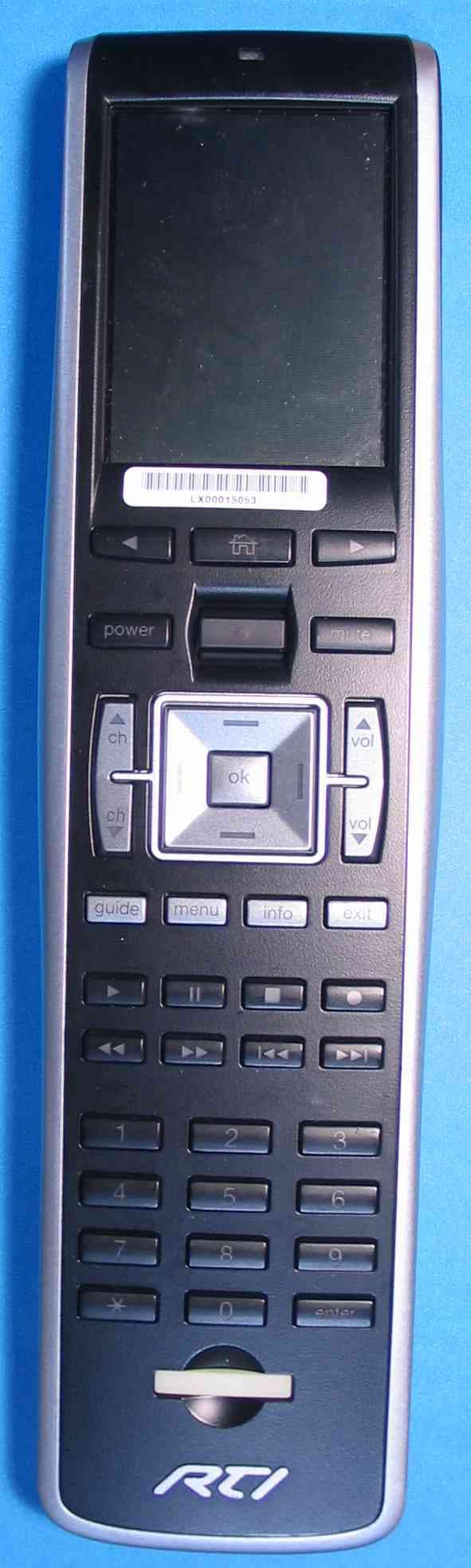
Click to zoom
Application Details
- Equipment Class
- DSC - Part 15 Security/Remote Control Transmitter
- Date of Grant
- Feb 08, 2007
- Application Purpose
- Original Equipment
- Date of Application
- Feb 08, 2007
- Equipment Note
- T2-C Universal System Controller
- Frequency Range
- 433.84000000 - 433.84000000
- Company
- Remote Technologies Inc
- Country
- United States
Documents & Files
Document Text
Text extracted from the exhibit documents filed with the FCC. Open a document above to read the original.
Users Manual
T2-C Universal System Controller 26 Standby Time on Full Charge 30 Days Battery Charge Time 3-4 Hours Total System Memory 32MBytes Flash (non-volatile) Device Capability Total number of devices limited only by memory Macro Capability Unlimited steps in a single macro Total number of macros limited only by memory Macros allowed on every button Communications USB programming port Dimensions Length: 10.0 in. (254mm) Width: 2.6 in. (66mm) Height: 1.0 in. (25mm) Enclosure High-impact molded ABS plastic Weight 9.6 oz. (272g) with battery pack Warranty One Year Parts & Labor (90 days on battery pack) All specifications are subject to change without notice. i FEDERAL COMMUNICATIONS COMMISSION NOTICE This equipment has been tested and found to comply with the limits for a Class B digital device, pursuant to Part 15 of the FCC Rules. These limits are designed to provide reasonable protection against harmful interference in a residential installation. This equipment generates, uses, and can radiate radio frequency energy and, if not installed and used in accordance with the instructions, may cause harmful interference to radio communications. However, there is no guarantee that interference will not occur in a particular installation. If this equipment does cause harmful interference to radio or television reception, which can be determined by turning the equipment off and on, the user is encouraged to try to correct the interference by one or more of the following measures: • Reorient or relocate the receiving antenna. • Increase the separation between the equipment and the receiver. • Connect the equipment into an outlet on a circuit different from that to which the receiver is connected. • Consult the dealer or an experienced radio/TV technician for help. This device complies with Part 15 of the FCC Rules. Operation is subject to the following two conditions: (1) this device may not cause harmful interference and (2) this device must accept any interference received, including interference that may cause undesired operation. FCC ID: MMURTI0600 CAN: 3166-RTI0600 T2-C Universal System Controller ii BATTERY DISPOSAL For environmental reasons, your T2-C universal system controller uses “environmentally sound” Lithium-ion rechargeable batteries. These batteries do not contain any poisonous heavy metals that can damage the environment. In the interest of recycling, please do not dispose of these batteries in the household waste at the end of their useful life. Instead, dispose of them at an appropriate collection site. SAFETY SUGGESTIONS Read Instructions. Read all safety and operating instructions before operating the unit. Heat. Keep the unit away from heat sources such as radiators, heat registers, stoves, etc., including amplifiers that produce heat. Power Sources. Connect the docking station only to the power supply that was included with the unit. Recharge the battery only with the docking station that was included with the unit. Power Cord Protection. Route power supply cords so that they are not likely to be walked on or pinched by items placed on or against them, paying particular attention to the cords at power receptacles and at the point at which they exit from the unit. Non-use Periods. Unplug the power supply from the outlet when the unit is to be left unused for a long period. Water and Moisture. Do not use the unit near water—for example, near a sink, in a wet basement, near a swimming pool, near an open window, etc. Object and Liquid Entry. Do not allow objects to fall or liquids to be spilled into the enclosure through openings. Cleaning. The unit should be cleaned only as recommended in the operating guide. Li-ion 25 Specifications Power 3.6 VDC, 1200 mAH Li-Ion Battery Pack Power Management Automatic On/Off (tilt switch) Infrared Control Range 30 Feet (9.1m) @ 60 Degrees Infrared Frequency Range 15kHz – 460kHz Radio Frequency Control Range Up to 100 Feet (30.5m) (with optional receivers) Radio Frequency Carrier 433MHz Operating Temperature +32°F to +122°F (+0°C to +50°C) Operating Humidity 5% to 95% Non-condensing Display High-brightness color TFT ¼ VGA (240 x 320 pixels) Supports 16-bit (65K) color Touchscreen High-resolution resistive Display size 2.8 in. (71mm) diagonal Backlights White LED (Display) Blue/Red/White LED (Keypad) Nominal Run Time on Full Charge 2½ hours min. continuous (5 - 7 days average use) T2-C Universal System Controller 24 If you are having a problem with hardware, please note the equipment in your system, a description of the problem, and any troubleshooting you have already tried. If you are having a problem with software, please note what version you have installed, the operating system on your PC, a description of the problem, and any troubleshooting you have already tried. If you are calling about a software or programming question or problem, please be at you computer when you place your call. This will considerably speed up the troubleshooting process. For Technical Support or assistance with your RTI product, contact RTI at: (952) 253-3137 [email protected] www.rticorp.com/support For questions regarding Service or Repair of your RTI product, contact RTI at: (952) 253-3136 [email protected] www.rticorp.com/service Please do not return products to RTI without return authorization. iii Servicing. Do not attempt any service beyond that described in the operating guide. Refer all other service needs to qualified service personnel. Damage Requiring Service. The unit should be serviced by qualified service personnel when: • The power supply cord or the plug has been damaged. • Objects have fallen or liquid has been spilled into the unit. • The unit does not appear to operate normally or exhibits a marked change in performance. LIMITED WARRANTY Remote Technologies Incorporated warrants its products for a period of one (1) year (90 days only for included battery packs) from the date of purchase from Remote Technologies Incorporated or an authorized Remot…
Text truncated - open the document above for the full version.
Block Diagram
Battery Voltage Regulators (Backlights) CPU Power Supply PXA255 3.6864Mhz Crystal Flash SDRAM Codec & Speakers 24.576 MHz RF Dau g hterboard Remote Technologies Incorporated TheaterTouch T2C System Controller Block/Signal Diagram 433 MHz Linx RF Transmitter 433Mhz Linx Splatch Antenna LCD Display
Cover Letter(s)
January 3, 2007 To: Intertek ETL Semko Subject: Confidentiality Request FCC ID: MMURTI0600 Pursuant to Sections 0.457 and 0.459 of the Commission’s Rules, the Applicant hereby requests confidential treatment of the following information accompanying this Application: – T2C Main Board Schematic – T2C RF Daughterboard Schematic The above materials contain trade secrets and proprietary information not customarily released to the public. The public disclosure of this information might be harmful to the Applicant and provide unjustified benefits to its competitors Sincerely, Paul Weichelt Electrical Engineer Remote Technologies, Inc. Remote Technologies, Inc. 7651 Anagram Drive Eden Prairie, MN 55344
Internal Photos
Figure 1: Main Board Top (Screen Top) Figure 2: Main Board Top (Screen Bottom) Figure 3: Main and Daughter Board Bottom Figure 4: Main Board Under Daughter Board Figure 5: Daughter Board Bottom Figure 6: Daughter Board Top Figure 7: Battery
Operational Description
Remote Technologies Incorporated •7630 Executive Dr. • Eden Prairie, MN 55344 • Tel. 612.937.2600 • Fax 612.937.7527 Universal System Controller Operational Description Purpose of the TheaterTouch The intended use of the Universal System Controller is to transmit IR, (infrared) control signals to home electronic devices. These devices include VCRs, DVD players, TV cable boxes, audio surround decoders, satellite receivers, televisions, etc. The Universal System Controller is a custom programmable device that contains a touchscreen display and keypad buttons. The Touchscreen display and keypad are programmed with the users set of electronic equipment and the parameters that can be controlled. The user interface on the touchscreen display is also custom programmable. The Universal System Controller is then programmed with the IR controls for each electronic device that the user desires to use. Universal System Controller Transmitter When the user interface for the electronic devices to be controlled and the IR control signals have been programmed into the Universal System Controller it is ready to use. When a user presses on the touchscreen or keypad to transmit, for example to start the play control on a VCR, the microprocessor, PXA255, senses the push. The PXA sends a serial command to the RF transmitter board. The control signal is modulated on the RF transmitter board and output. The RF signal is received by an external device and converted to an IR signal to control the intended device. The PXA255 microprocessor uses an internal PLL running at 200 MHz which is fed from an external 3.6864 crystal. The RF module uses an internal 433MHz SAW oscillator. TheaterTouch Antenna The antenna on the Universal System Controller is a grounded line SMD Planar (Splatch), soldered to the RF module, internal to the chassis and is not easily accessible.
Test Report
This report is for the exclusive use of Intertek's Client and is provided pursuant to the agreement between Intertek and its Client. Intertek's responsibility and liability are limited to the terms and conditions of the agreement. Intertek assumes no liability to any party, other than to the Client in accordance with the agreement, for any loss, expense or damage occasioned by the use of this report. Only the Client is authorized to copy or distribute this report and then only in its entirety. Any use of the Intertek name or one of its marks for the sale or advertisement of the tested material, product or service must first be approved in writing by Intertek. The observations and test results in this report are relevant only to the sample tested. This report by itself does not imply that the material, product, or service is or has ever been under an Intertek certification program. TEST REPORT Report Number: 3107561LEX-001 Project Number: 3107561 Evaluation of the T2-C Universal System Controller Model Number: T2-C FCC ID: MMURTI0600 ICID: 3166-RTI0600 Tested to the Criteria in: FCC Part 15 Subpart C, RSS-210, and ICES-003 For Remote Technologies Inc. Test Performed by: Test Authorized by: Intertek 731 Enterprise Drive Lexington, KY 40510 Remote Technologies Inc. 7651 Anagram Drive Eden Prairie, MN 55344 Prepared By:_______________________________Date:____11/27/2006________ Bryan C. Taylor, Team Leader Approved By:______________________________Date:____11/27/2006_________ Jason Centers, Senior Project Engineer Intertek 731 Enterprise Drive, Lexington, KY 40510 Tele phone: 859-226-1000 Fax: 859-226-1040 Web: www.etlsemko.com 731 Enterprise Drive, Lexington KY 40510 Evaluation For:Remote Technologies Inc. FCC ID: MMURTI0600 Model No: T2-C Report Number: 3107561LEX-001 Page 2 of 14 TABLE OF CONTENTS 1 EXECUTIVE SUMMARY................................................................................................................. 3 2 JOB DESCRIPTION .......................................................................................................................... 4 2.1 CLIENT INFORMATION.................................................................................................................... 4 2.2 EQUIPMENT UNDER TEST (EUT) .................................................................................................... 4 2.3 SYSTEM SUPPORT EQUIPMENT....................................................................................................... 4 2.4 CABLES ASSOCIATED WITH EUT .................................................................................................... 4 2.5 TEST CONFIGURATION.................................................................................................................... 5 2.6 MODIFICATIONS REQUIRED FOR COMPLIANCE............................................................................... 5 2.7 RELATED SUBMITTAL(S) GRANTS.................................................................................................. 5 2.8 BLOCK DIAGRAM........................................................................................................................... 5 3 TEST FACILITY................................................................................................................................ 6 3.1 TEST EQUIPMENT............................................................................................................................ 7 4 TRANSMITTING TIME ................................................................................................................... 8 4.1 TEST PROCEDURE........................................................................................................................... 8 4.2 TEST RESULTS................................................................................................................................8 5 FIELD STRENGTH OF FUNDAMENTAL AND SPURIOUS RADIATION ............................. 9 5.1 TEST PROCEDURE........................................................................................................................... 9 5.2 TEST RESULTS.............................................................................................................................. 10 6 BANDWIDTH OF EMISSIONS ..................................................................................................... 11 6.1 TEST PROCEDURE......................................................................................................................... 11 6.2 TEST RESULTS.............................................................................................................................. 11 7 POWER LINE CONDUCTED EMISSIONS ................................................................................. 12 7.1 TEST PROCEDURE......................................................................................................................... 12 7.2 TEST RESULTS.............................................................................................................................. 12 8 RADIATED EMISSIONS ................................................................................................................ 13 8.1 TEST PROCEDURE......................................................................................................................... 13 8.2 TEST RESULTS.............................................................................................................................. 14 731 Enterprise Drive, Lexington KY 40510 Evaluation For:Remote Technologies Inc. FCC ID: MMURTI0600 Model No: T2-C Report Number: 3107561LEX-001 Page 3 of 14 1 EXECUTIVE SUMMARY Testing performed for: Remote Technologies Inc. Equipment Under Test: T2-C The T2-C manufactured by Remote Technologies Inc. was tested to and found to be compliant with the tests listed in the following table. Test Description FCC Rule IC Rule Results Page Transmitting Time FCC Part 15…
Text truncated - open the document above for the full version.
Test Setup Photos
Figure 1: Back Side of Emissions Setup (Remote in Charging Base) Figure 2: Front Side of Emissions Setup (Remote in Charging Base) Figure 3: Emissions Test Setup (Transmitting)
Contact Information
Applicant
Kevin Marty(Chief Technology Officer)
Technical Contact
Remote TechnologiesPaul Weichelt
[email protected]952-253-3100
7651 Anagram Drive · Eden Prairie, Minnesota · United States
Non-Technical Contact
Remote Technologies Inc.John Demskie
[email protected]952-253-3100
Test Firm
Intertek Testing Services NA Inc.Bryan Taylor
Technical Specifications
| # | Rule Parts | Frequency Range | Power Output |
|---|---|---|---|
| 1 | 15.231 | 433.84 MHz - 433.84 MHz | - |
Other Applications from Remote Technologies Inc
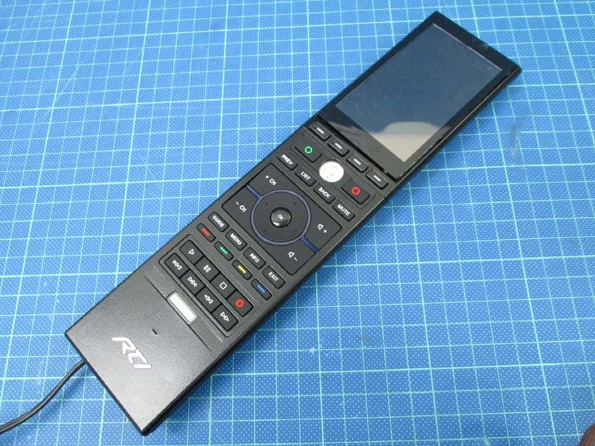
MMURTI2100
Mar 25, 2015APM 6998 WiFi Module
Equipment Class
DTS - Digital Transmission System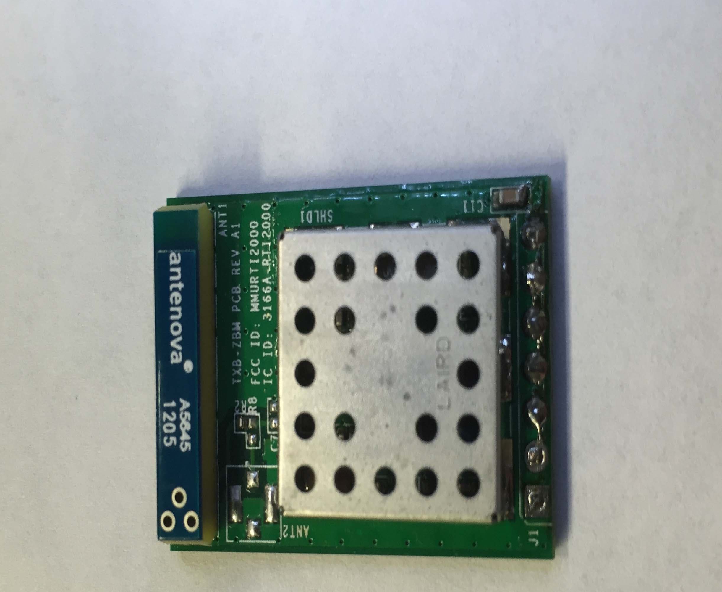
MMURTI2000
Feb 16, 2015TXB-ZBM
Equipment Class
DTS - Digital Transmission System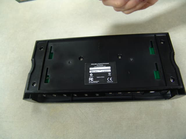
MMURTI1800
Jun 01, 2011ProLink.z Control Processor
Equipment Class
DXX - Part 15 Low Power Communication Device Transmitter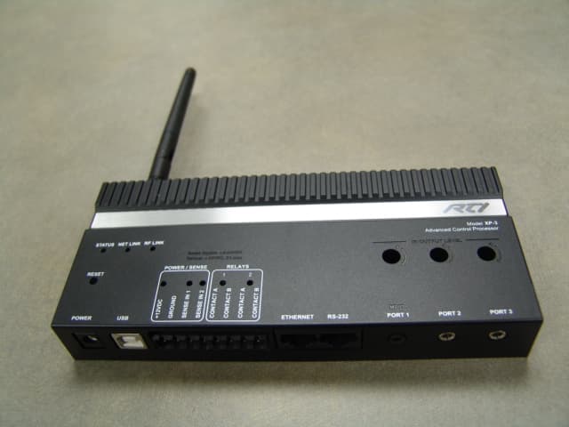
MMURTI1900
May 23, 2011Advanced Control Processor
Equipment Class
DXT - Part 15 Low Power Transceiver, Rx Verified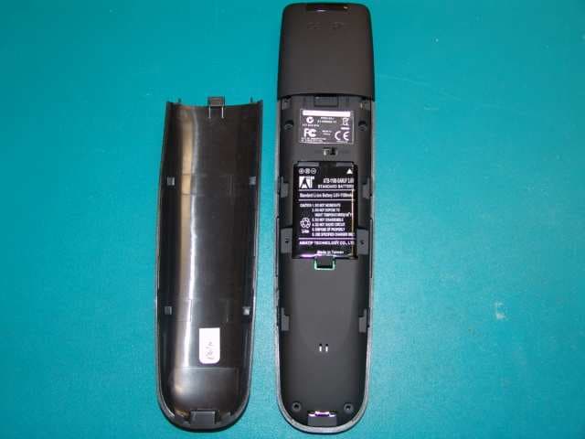
MMURTI1700
Mar 31, 2011Remote Controller
Equipment Class
DSC - Part 15 Security/Remote Control Transmitter