MMURTI1600W2SW0001 RF Module
Remote Technologies Inc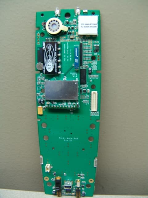
Click to zoom
Application Details
- Equipment Class
- DTS - Digital Transmission System
- Date of Grant
- Dec 09, 2010
- Application Purpose
- Original Equipment
- Date of Application
- Dec 09, 2010
- Equipment Note
- W2SW0001 RF Module
- Frequency Range
- 2400.00000000 - 2483.50000000
- Company
- Remote Technologies Inc
- Country
- United States
Documents & Files
Document Text
Text extracted from the exhibit documents filed with the FCC. Open a document above to read the original.
Users Manual
Wi2Wi W2SW0001 WiFi Module w/ Pulse W3008C Antenna Installation Instructions Purpose of the TXB-DB Dual Transmitter Module The Wi2Wi W2SW0001 WiFi Module w/ Pulse W3008C Antenna (“module”) can be installed in applicable Remote Technologies Inc. (“RTI”) products only. This module is not sold retail by RTI, nor is it provided by RTI as an OEM product to other manufacturers or companies for installation into their products. RTI and its authorized Contract Manufacturers are the only authorized installers of this module and it is not provided as a field or end-user upgrade. When properly and permanently installed in an applicable RTI product, the module will provide 802.11 b/g WiFi communication. Installation Instructions When the module is installed in an RTI product it is permanently affixed to the host product and cannot be removed without the use of additional equipment. This module is also not visible, nor accessible by the end-user. Any attempted access or removal of the module by anyone other than RTI or its authorized Contract Manufacturers is strictly prohibited. When installed in a host RTI product, the host RTI product will display verbiage to the effect of the following in accordance with FCC 47 CFR Part 15 Section 15.212: Contains Transmitter Module FCC ID: MMURTI1600 Contains IC: 3166A‐RTI1600 or Contains FCC ID: MMURTI1600 Contains IC: 3166A‐RTI1600 The Operation Manual of the host RTI product will also display the following information in accordance with FCC 47 CFR Part 15 Section 15.19: This device complies with Part 15 of the FCC Rules. Operation is subject to the following two conditions: (1) This device may not cause harmful interference. (2) This device must accept any interference received, including interference that may cause undesired operation.
Attestation Statements
FCC ID: MMURTI1600 Part 15 Unlicensed Modular Transmitter Approval Justification per DA 00-1407, released: June 26, 2000 requirement reference 1 The modular transmitter must have its own RF shielding. The module contains its own custom shield. Wi2Wi part number W2SW0001-SHLD. 2 The modular transmitter must have buffered modulation/data inputs The W2SW0001 SIP contains TX and RX Buffer Management schemes. 3 The modular transmitter must have its own power supply regulation. The W2SW0001 contains an internal power regulator that takes a 3.3V unregulated supply and generates both 1.8V analog and 1.8V IO voltages. 4 The modular transmitter must comply with the antenna requirements of Section 15.203 and 15.204(c). The unit uses a permanently attached surface mount antennas. The unit can also only be installed and repaired by RTI. It is not end-user accessible/serviceable. There is no authorized external power amplifier that may be used with either bands of this device. 5 The modular transmitter must be tested in a stand-alone configuration, i.e., the module must not be inside another device during testing. The module was tested with a support board to enable proper operation. 6 The modular transmitter must be labeled with its own FCC ID number, and, if the FCC ID is not visible when the module is installed inside another device, then the outside of the device into which the module is installed must also display a label referring to the enclosed module. See “MMU-RTI1600 Labeling Information.doc” 7 The modular transmitter must comply with any specific rule or operating requirements applicable to the transmitter and the manufacturer must provide adequate instructions along with the module to explain any such requirements. A copy of these instructions must be included in the application for equipment authorization. No Specific Rules are Applicable 8 The modular transmitter must comply with any applicable RF exposure requirements. For example, FCC Rules in Sections 2.1091, 2.1093 and specific Sections of Part 15, including 15.319(i), 15.407(f), 15.253(f) and 15.255(g), require that Unlicensed PCS, UNII and millimeter wave devices perform routine environmental evaluation for RF Exposure to demonstrate compliance. In addition, spread spectrum transmitters operating under Section 15.247 are required to address RF Exposure compliance in accordance with Section 15.247(b)(4). Not Applicable
Cover Letter(s)
No vember 17, 2010 Attention: Intertek Testing Services ETL Semko Re: Request for confidentiality Applicant: Remote Technologies, Inc. FCC ID: MMURTI1600 To whom it may concern, Permanent Confidentiality Request is hereby submitted by Remote Technologies, Inc. to withhold permanently from public review certain portions of the application for equipment certification for the referenced FCC identifiers. This request for confidentiality is made pursuant to 47 CFR 0.457(d) and 0.459 of the FCC Rules. In particular, the following sections of the application are to be kept permanently confidential: Schematics Detailed Block diagrams Detailed Operational/Functional Description Rationale for request for confidentiality: Remote Technologies, Inc. has invested considerable time and materials in research and development to produce the referenced product. Disclosure of the permanently confidential portions of this application to competitors would not only give them significant competitive advantages in developing similar products, but would also disclose successful implementation of unpublished, leading edge technology developed by us. Sincerely, Kevin Marty Chief Technology Officer Remote Technologies, Inc. 1(1)
ID Label/Location Info
Wi2Wi W2SW0001 WiFi Module w/ Pulse W3008C Antenna (“Module”) Labeling Information Labeling Information When the Module is installed in Remote Technologies Inc. (“RTI”) product it is permanently affixed to the host product and cannot be removed without the use of additional equipment. This Module is also not visible, nor accessible by the end-user. Any attempted access or removal of the Module by anyone other than RTI or its authorized Contract Manufacturers is strictly prohibited. The Module will contain the following FCC Identifier in accordance with FCC 47 CFR Part 15, Section 19 and FCC 47 CFR Part 2, Section 925: FCC ID MMURTI1600 The FCC Identifier will be displayed on the Module via a permanently adhered label to its shield. When installed in a host RTI product, the host RTI product will display verbiage to the effect of the following in accordance with FCC 47 CFR Part 15, Section 212: Contains Transmitter Module FCC ID: MMURTI1600 Contains IC: 3166A‐RTI1600 or Contains FCC ID: MMURTI1600 Contains IC: 3166A‐RTI1600 The Operation Manual of the host RTI product will also display the following information in accordance with FCC 47 CFR Part 15, Section 19: This device complies with Part 15 of the FCC Rules. Operation is subject to the following two conditions: (1) This device may not cause harmful interference. (2) This device must accept any interference received, including interference that may cause undesired operation.
Test Report
TEST REPORT Report Number: 100173241MIN-005M Project Number: G100173241 Testing performed on the W2SW0001 FCC ID: MMU-RTI1600 Industry Canada ID: 3166A- RTI1600 to 47 CFR Part 15. 247:2009 RSS- 210, Issue 7, 2007 For Remote Technologies Inc. Test Performed by: Test Authorized by: Intertek Testing Services NA, Inc. 7250 Hudson Blvd., Suite 100 Oakdale, MN 55128 Remote Technologies Inc. 5775 12 th Avenue East, Suite 180 Shakopee, MN 55379 Prepared by: Date:August 2, 2010 Uri Spector Reviewed by: Date: August 2, 2010 Norman Shpilsher This report is for the exclusive use of Intertek's Client and is provided pursuant to the agreement between Intertek and its Client. Intertek's responsibility and liability are limited to the terms and conditions of the agreement. Intertek assumes no liability to any party, other than to the Client in accordance with the agreement, for any loss, expense or damage occasioned by the use of this report. Only the Client is authorized to copy or distribute this report and then only in its entirety. Any use of the Intertek name or one of its marks for the sale or advertisement of the tested material, product or service must first be approved in writing by Intertek. The observations and test results in this report are relevant only to the sample tested. This report by itself does not imply that the material, product, or service is or has ever been under an Intertek certification program. This report must not be used to claim product endorsement by A2LA, NIST nor any other agency of the U.S. Government. EMC Report No: 100173241MIN-005M FCC ID: MMU-RTI1600 IC ID: 3166A-RTI1600 Page 2 of 26 TABLE OF CONTENTS 1.0 GENERAL DESCRIPTION..........................................................................................................3 1.1 Product Description; Test Facility......................................................................................4 1.3 Environmental conditions ..................................................................................................5 1.4 Measurement uncertainty..................................................................................................6 1.5 Field Strength Calculation .................................................................................................6 2.0 TEST SUMMARY..........................................................................................................................7 3.0 TEST CONDITIONS AND RESULTS........................................................................................8 3.1 Maximum peak output power ............................................................................................8 3.2 Radiated spurious emissions ..........................................................................................10 3.3 RF Exposure Compliance ...............................................................................................25 4.0 TEST EQUIPMENT.....................................................................................................................26 EMC Report No: 100173241MIN-005M FCC ID: MMU-RTI1600 IC ID: 3166A-RTI1600 Page 3 of 26 1.0 GENERAL DESCRIPTION Model: W2SW0001 Type of EUT: Digital Transmission Module Serial Number: N/A FCC ID: MMU-RTI1600 Industry Canada ID: 3166A- RTI1600 Related Submittal(s) Grants: None Company: Remote Technologies Inc. Customer: Mr. Mark Melville Address: 5775-12 th Avenue East Suite 180 Shakopee MN 55379 Phone: (952) 253-3116 Fax: (952) 253-3131 e-mail: [email protected] Test Standards: 47 CFR, Part 15:2009, §15.247 RSS–210, Issue 7, 2007 RSS-Gen, Issue 2, 2007 47 CFR, Part 15:2009, §15.107 and §15.109, Class B Other Note: Enclosure Radiated Emissions measurements, Maximum Peak Output Power and Exposure Compliance calculations were performed for Class II Permissive Changes Type of radio: Stand -alone Module Hybrid Date Sample Submitted: July 19, 2010 Test Work Started: July 19, 2010 Test Work Completed: July 28, 2010 Test Sample Conditions: Damaged Poor (Usable) Good EMC Report No: 100173241MIN-005M FCC ID: MMU-RTI1600 IC ID: 3166A-RTI1600 Page 4 of 26 1.1 Product Description; Test Facility Product Description: 2.40 – 2.4835GHz Digital Transmission Module Transmitter Type: FHSS Digital Modulation WiFi Blue Tooth Operating Frequency Range(s): Range From 2400 to 24835 MHz Number of Channels: 11 Modulation: OFDM for 802.11/g Emission Designator: 16M5F9X Antenna(s) Info: Antenna Type: Omni directional Gain: 2.2dBi Connector Type: Solder direct to circuit board (The EUT does not have antenna port connector, therefore no measurements were performed at antenna port) Antenna Installation: User Professional Factory Transmitter power configuration: Internal battery External power source 120VAC 230VAC 400VAC 3.3VDC Other: Amp. 50Hz 60Hz Special Test Arrangement: As a hand-held device the EUT was rotated through three orthogonal axes to determine and tested with the maximum emissions Test Facility Accreditation: A2LA (Certificate No. 1427.01) Test Methodology: Measurements performed according to the procedures in ANSI C63.4- 2003 and FCC Public Notice DA 00-705 EMC Report No: 100173241MIN-005M FCC ID: MMU-RTI1600 IC ID: 3166A-RTI1600 Page 5 of 26 1.2 EUT Configuration The equipment under test was operated during the measurement under the following conditions: - Standby - Continuous transmissions (modulated signal) - Continuous transmissions (un-modulated signal) - Continuous receiving - Test program (customer specific) - Operating modes of the EUT: No. Description 1 Test was performed at low channel 1, middle channel 6, and upper channel 11 and was transmitting CW signal. Cables: No. Type Length Designation Note 1 None Support equipment/Services: No. Item Description 1 None 1.3 Environmental conditions During the measurement the environmental conditions were within the listed ranges: Normal Temperature: +15 to +35 ° C Humidity: 20-75 % Atmospheric pressure: 86-106 kPa Extreme Temperature: -20 to +50 …
Text truncated - open the document above for the full version.
Contact Information
Applicant
John Demskie(President)
Technical Contact
Remote TechnologiesMark Meville
[email protected]952-253-3100
5775 12 Ave East · Shakopee, Minnesota · United States
Test Firm
Intertek Testing ServicesUri Spector
Technical Specifications
| # | Rule Parts | Frequency Range | Power Output |
|---|---|---|---|
| 1 | 15C | 2.40 GHz - 2.48 GHz | 1.37 mW |
Other Applications from Remote Technologies Inc
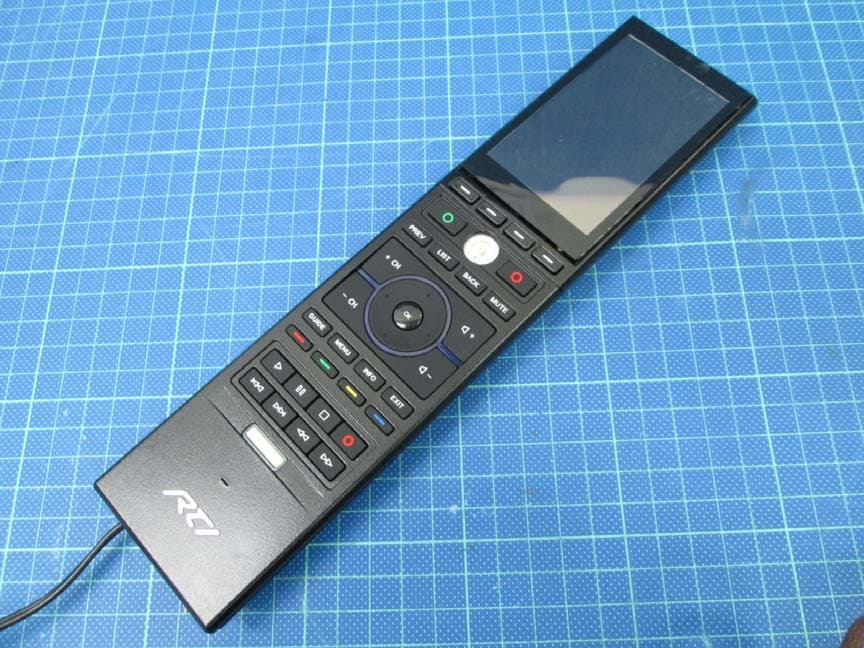
MMURTI2100
Mar 25, 2015APM 6998 WiFi Module
Equipment Class
DTS - Digital Transmission System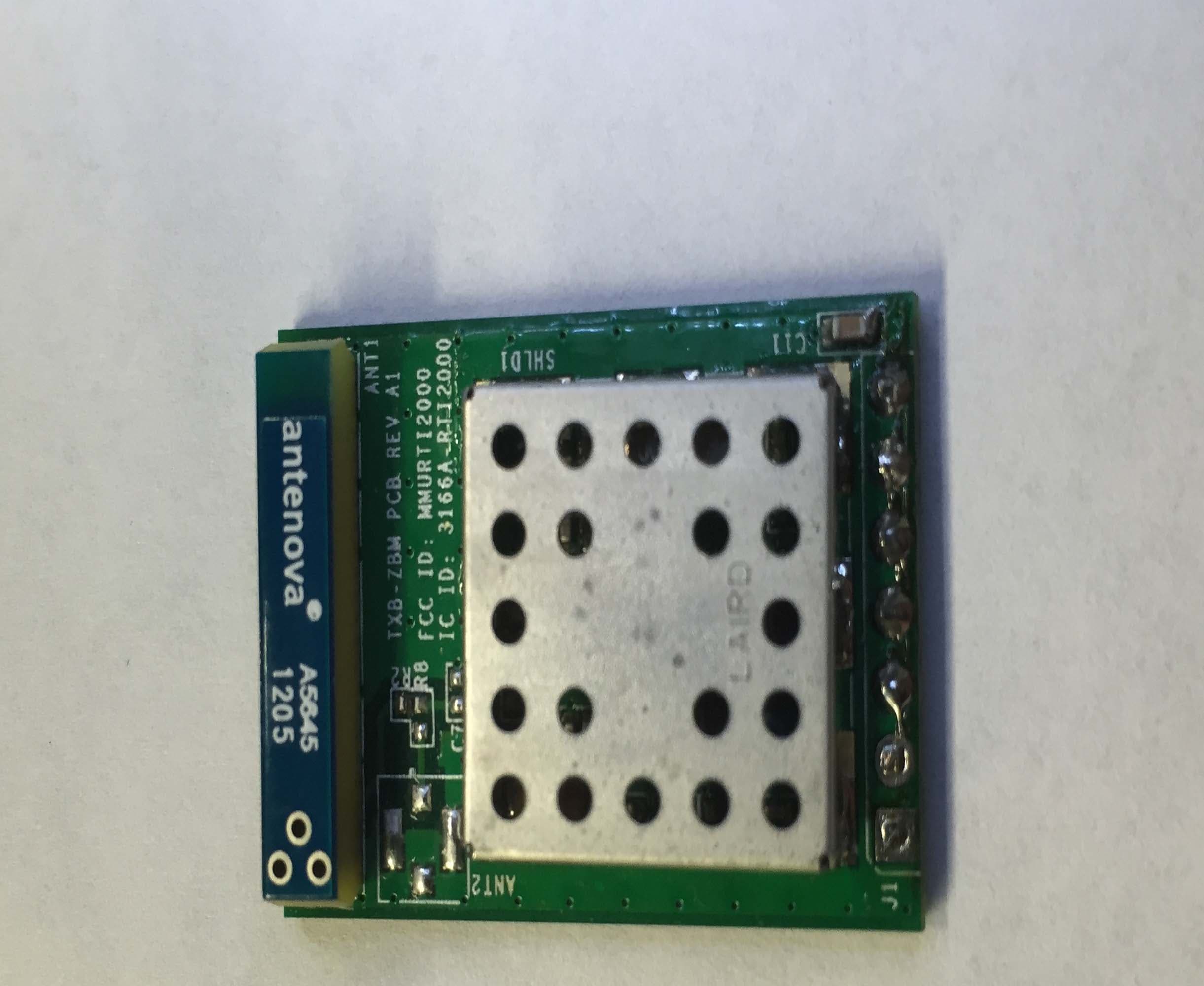
MMURTI2000
Feb 16, 2015TXB-ZBM
Equipment Class
DTS - Digital Transmission System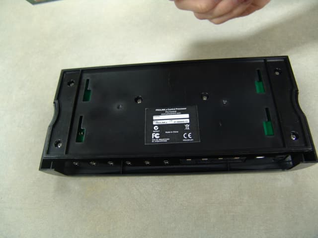
MMURTI1800
Jun 01, 2011ProLink.z Control Processor
Equipment Class
DXX - Part 15 Low Power Communication Device Transmitter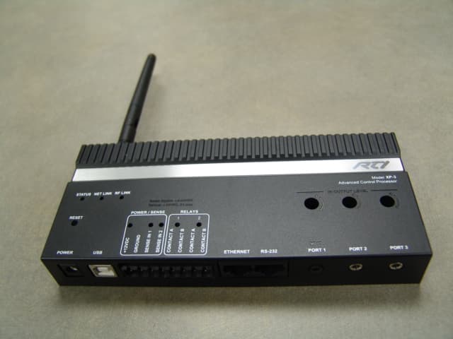
MMURTI1900
May 23, 2011Advanced Control Processor
Equipment Class
DXT - Part 15 Low Power Transceiver, Rx Verified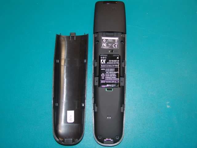
MMURTI1700
Mar 31, 2011Remote Controller
Equipment Class
DSC - Part 15 Security/Remote Control Transmitter