MNT-PC-UC-1OSMAC Base
Vytek Inc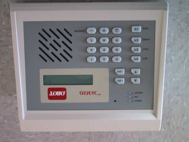
Click to zoom
Application Details
- Equipment Class
- TNB - Licensed Non-Broadcast Station Transmitter
- Date of Grant
- Mar 29, 2001
- Application Purpose
- Original Equipment
- Date of Application
- Mar 29, 2001
- Equipment Note
- OSMAC Base
- Frequency Range
- 450.00000000 - 470.00000000
- Company
- Vytek Inc
- Country
- United States
Documents & Files
Document Text
Text extracted from the exhibit documents filed with the FCC. Open a document above to read the original.
Users Manual
OSMAC BaseOSMAC Base User Manual Page 1 OSMAC BaseOSMAC Base On-Site Communications System User Manual Firmware Version 307D55 Sonik Technologies Corp. 310 Via Vera Cruz San Marcos, CA 92069 PH: 760-752-1011 Fax: 760-752-1411 Email: [email protected] OSMAC BaseOSMAC Base User Manual Page 2 Table Of Contents 1 Installation........................................................................................................................................................................4 1.1 Environment............................................................................................................................................................4 1.2 Licensing.................................................................................................................................................................4 1.3 Radio Communication Interference....................................................................................................................4 1.4 Locating the ............................................................................................................................................................4 1.5 Unit Setup................................................................................................................................................................4 2 Local Operation...............................................................................................................................................................5 2.1 Overview.................................................................................................................................................................5 2.2 Keypad.....................................................................................................................................................................6 2.3 External Keyboard.................................................................................................................................................6 2.4 Display.....................................................................................................................................................................7 2.5 Sending a page........................................................................................................................................................7 2.6 Group Page..............................................................................................................................................................8 2.7 Tone Paging............................................................................................................................................................8 2.8 2-way voice communications...............................................................................................................................8 2.9 Alarm Pages............................................................................................................................................................8 3 Two-way Radio and Telephone Operation.................................................................................................................9 3.1 Sending Pages from the Two-Way Radio..........................................................................................................9 3.2 Placing Telephone Calls from the Two-Way Radio......................................................................................10 3.3 Autodial Calls.......................................................................................................................................................10 3.4 Receiving Telephone Calls at the Two-Way radio.........................................................................................11 3.5 Sending Pages using the Telephone Interface.................................................................................................12 4 Unit Setup.......................................................................................................................................................................13 4.1 Configuration Mode.............................................................................................................................................15 5 Program Mode...............................................................................................................................................................18 5.1 Assign Pager.........................................................................................................................................................18 5.2 Assigning a Group...............................................................................................................................................19 5.3 Sending Test Pages..............................................................................................................................................21 5.4 Alarm Pages..........................................................................................................................................................21 5.5 Phone Autodial Memories..................................................................................................................................22 6 Diagnostics.....................................................................................................................................................................23 6.1 Built-in Diagnostics.............................................................................................................................................23 6.2 Remote Diagnostics.............................................................................................................................................23 7 Serial Port Protocols..............................................................................................................................…
Text truncated - open the document above for the full version.
Attestation Statements
Report No. 101370-08 (FCC ID: MNT-PC-US-1) Page 1 Rev.No 1.0 ATTESTATION STATEMENT GENERAL REMARKS: SUMMARY: All tests were performed per CFR 47, Part 2, Paragraphs 2.1046; 2.1047(a); 2.1047(b); 2.1049; 2.1051; 2.1053; 2.1055(a)(1);2.1055(d); Part 22, Paragraph 22.359; and Part 90, Paragraphs 90.210(b) and 90.214 n - Performed The Equipment Under Test n - Fulfills the requirements of CFR 47, Part 2, Paragraphs 2.1046; 2.1047(a); 2.1047(b); 2.1049; 2.1051; 2.1053; 2.1055(a)(1);2.1055(d); Part 22, Paragraph 22.359; and Part 90, Paragraphs 90.210(b) and 90.214 - TÜV PRODUCT SERVICE, INC. - Responsible Engineer: Mary Washington (EMC Senior Engineer)
Block Diagram
Principles of Operation The OSMAC Base is a multi-functional unit that can be used to communicate between the built-in speaker/microphone, pagers, two-way radios and the telephone interface. The internal circuitry is comprised of numerous elements as shown on the block diagram below. These include radio transceiver, telephone interface, microprocessor, front panel I/O, DTMF encoder/decoder, CTCSS encoder/decoder, speech synthesizer (DAC), microphone amplifier, speaker amplifier, analog filters, limiting amplifier and analog switch matrix. The microprocessor controls all circuitry as needed for the desired communication function. The encoders generate needed audio signals and the decoders detect incoming control signals on the received audio. Analog switches route the analog signals within the unit. Control Bus Mic Speaker Antenna Analog Switch Matrix Radio Transceiver Front Panel FilterLimiter Telephone Interface Phone Line DTMF (3.579 MHz) CTCSS (4 MHz) DAC Microprocessor (48 MHz) RS232 Port 1 RS232 Port 2 Keyboard Alarm Inputs
Cover Letter(s)
Agent Authorization Letter March 9, 2001 Sonik Technologies 2310 Cousteau Court Vista, CA 92083 Dear Sir or Madam, We, Sonik Technologies, hereby authorize TUV Product Service (10040 Mesa Rim Road, San Diego, CA 92121, Tel. (858) 546-3999) to act as our agent in all matters relating to applications for equipment authorization, including the signing of all documents relating to these matters. I further certify that neither the applicant nor any party to this application is subject to a denial of Federal benefits. This includes FCC benefits pursuant to Section 5301 of the Anti-Drug Abuse Act of 1988, 21 U.S.C. Section 862. This authorization expires on March 1, 2002. Sincerely, Art Lashbrook VP Engineering (760) 536-1000
External Photos
Bottom Rear Top
Internal Photos
Main board bottom left corner Bottom right corner Display board back ‘ Display board front Inside top cover Keypad board back Keypad board front Main board back Main board center Main board end Main board full Main board full 1 Main board left side Main board side Main board top left Main board switch inserted Radio module board back Radio module board side Radio Module board side 2 Radio module board side 3 Radio module board top Top view cover removed main board with covers
Operational Description
Spurious radiation is limited by bypass capacitors on wires going to connectors on the rear panel. These are typically 1000 pF in value and are shown on the schematic. The telephone interface also has ferrite beads for additional suppression. These are L1 and L2 in the bill of material.
Parts List/Tune Up Info
Run Date: 03/22/01 Sonik Technologies Corporation Page: 1 B/M Date: 03/22/01 SINGLE-LEVEL BILL OF MATERIALS REPORT Time: 11:50 AM WITHOUT PHANTOM BLOW THROUGH =================================================================================================================================== BILL REVISION TYPE U/M DESCRIPTION ----------------------------------------------------------------------------------------------------------------------------------- 5A296-1 E1 (CURRENT) STANDARD EACH Assy,PF1 Central Processor LAST USED: 03/20/01 MAX LOT SIZE: 0 DRAWING: 296 REV: E COMPONENT REV TYP QTY/BILL U/M DESCRIPTION FIND# STEP ----------------------------------------------------------------------------------------------------------------------------------- 0P296 1.00 EACH PCB,Blank,PF1 Central Processo A100 3B378-220-F 2.00 EACH Heat Sink,T0-220,6.8 C/W,thru A104 3H176-6909-1 4.00 EACH Standoff,aluminum,7/8 in,swage A150 3H254-632 1.00 EACH Nut,632,steel A110 3H235-6 1.00 EACH Flatwasher,Zinc,#6 A115 3H263-6 1.00 EACH Lockwasher,#6 A120 3H255-6-375 1.00 EACH Screw,phil,p-hd,stl,6x32x0.375 A125 3H235-2 4.00 EACH Flatwasher,Zinc,#2 A135 3H263-2 4.00 EACH Lockwasher,#2 A140 3H255-2-25 4.00 EACH Screw,Phil,p-hd,stl,2x56x0.25 A145 1Y143-A 2.00 EACH Crystal insulator for HC-49 A160 3M334-1 1.00 EACH Shield Fence,Digital Section f A210 3M334-2 1.00 EACH Shield Cover, Digital Section A211 1C144-104 1.00 EACH Cap,cer,10%,X7R,1206,50V,0.1uF C1 1C144-104 1.00 EACH Cap,cer,10%,X7R,1206,50V,0.1uF C2 1C144-104 1.00 EACH Cap,cer,10%,X7R,1206,50V,0.1uF C3 1C144-104 1.00 EACH Cap,cer,10%,X7R,1206,50V,0.1uF C4 1C144-104 1.00 EACH Cap,cer,10%,X7R,1206,50V,0.1uF C5 1C144-104 1.00 EACH Cap,cer,10%,X7R,1206,50V,0.1uF C6 1C144-104 1.00 EACH Cap,cer,10%,X7R,1206,50V,0.1uF C7 1C144-104 1.00 EACH Cap,cer,10%,X7R,1206,50V,0.1uF C8 1C144-104 1.00 EACH Cap,cer,10%,X7R,1206,50V,0.1uF C9 1C144-104 1.00 EACH Cap,cer,10%,X7R,1206,50V,0.1uF C10 1C144-104 1.00 EACH Cap,cer,10%,X7R,1206,50V,0.1uF C11 1C144-104 1.00 EACH Cap,cer,10%,X7R,1206,50V,0.1uF C12 1C144-104 1.00 EACH Cap,cer,10%,X7R,1206,50V,0.1uF C13 1C144-104 1.00 EACH Cap,cer,10%,X7R,1206,50V,0.1uF C14 1C144-104 1.00 EACH Cap,cer,10%,X7R,1206,50V,0.1uF C15 1C143-104 1.00 EACH Cap,cer,10%,X7R,0805,50V,0.1uF C16 1C112-180 1.00 EACH Cap,cer,5%,NPO,0805,50V,18pF C17 1C244-Q106 1.00 EACH Cap,tant,20V,SMT,C case,10 uF, C18 1C118-105 1.00 EACH Cap,tant,20%,16V,A case,1uF C19 1C112-330 1.00 EACH Cap,cer,5%,NPO,0805,50V,33pF C20 1C143-103 1.00 EACH Cap,cer,10%,X7R,0805,50V,0.01u C21 1C399-472 1.00 EACH Cap,cer,5%,X7R,0805,50V,4700pF C22 1C398-393 1.00 EACH Cap,cer,5%,X7R,1206,50V,.039uF C23 1C398-104 1.00 EACH Cap,cer,5%,X7R,1206,50V,0.1uF C24 1C143-104 1.00 EACH Cap,cer,10%,X7R,0805,50V,0.1uF C25 1C143-104 1.00 EACH Cap,cer,10%,X7R,0805,50V,0.1uF C26 1C143-102 1.00 EACH Cap,cer,10%,X7R,0805,50V,1000p C27 1C143-102 1.00 EACH Cap,cer,10%,X7R,0805,50V,1000p C28 1C118-105 1.00 EACH Cap,tant,20%,16V,A case,1uF C29 1C143-102 1.00 EACH Cap,cer,10%,X7R,0805,50V,1000p C30 1C143-102 1.00 EACH Cap,cer,10%,X7R,0805,50V,1000p C31 1C143-102 1.00 EACH Cap,cer,10%,X7R,0805,50V,1000p C32 1C118-105 1.00 EACH Cap,tant,20%,16V,A case,1uF C33 Run Date: 03/22/01 Sonik Technologies Corporation Page: 2 B/M Date: 03/22/01 SINGLE-LEVEL BILL OF MATERIALS REPORT Time: 11:50 AM WITHOUT PHANTOM BLOW THROUGH =================================================================================================================================== BILL REVISION TYPE U/M DESCRIPTION ----------------------------------------------------------------------------------------------------------------------------------- 5A296-1 E1 (CURRENT) STANDARD EACH Assy,PF1 Central Processor COMPONENT REV TYP QTY/BILL U/M DESCRIPTION FIND# STEP ----------------------------------------------------------------------------------------------------------------------------------- 1C118-105 1.00 EACH Cap,tant,20%,16V,A case,1uF C34 1C399-272 1.00 EACH Cap,cer,5%,X7R,0805,50V,2700pF C35 1C112-101 1.00 EACH Cap,cer,5%,NPO,0805,50V,100pF C36 1C398-104 1.00 EACH Cap,cer,5%,X7R,1206,50V,0.1uF C37 1C398-273 1.00 EACH CAP,cer,5%,X7R,1206,.027uF C38 1R454-102 * STD 1.00 EACH Res,5%,SMT,2010,1K ohm C39 1C247-1E101 1.00 EACH Cap,electrolytic,25V,100uF,thr C40 1C244-Q106 1.00 EACH Cap,tant,20V,SMT,C case,10 uF, C41 1C117-475 1.00 EACH Cap,tant,20%,10V,A case,4.7uF C42 1C112-101 1.00 EACH Cap,cer,5%,NPO,0805,50V,100pF C43 1C112-120 1.00 EACH Cap,cer,5%,NPO,0805,50V,12pF C44 NP 0.00 EACH No placement for this referenc C45 1C143-222 1.00 EACH Cap,cer,10%,X7R,0805,50V,2200p C46 1C143-104 1.00 EACH Cap,cer,10%,X7R,0805,50V,0.1uF C47 1C112-121 1.00 EACH Cap,cer,5%,NPO,0805,50V,120pF C48 1C398-123 1.00 EACH CAP,cer,5%,X7R,1206,.012uF C49 1C112-101 1.00 EACH Cap,cer,5%,NPO,0805,50V,100pF C50 1C206-336 1.00 EACH Cap,tant,10%,6V,C case,33uF,Lo C51 NP 0.00 EACH No placement for this referenc C52 NP 0.00 EACH No placement for this referenc C53 1C143-104 1.00 EACH Cap,cer,10%,X7R,0805,50V,0.1uF C54 1C143-104 1.00 EACH Cap,cer,10%,X7R,0805,50V,0.1uF C55 1C244-Q106 1.00 EACH Cap,tant,20V,SMT,C case,10 uF, C56 1C143-153 1.00 EACH Cap,cer,10%,X7R,0805,50V,0.015 C57 1C244-Q106 1.00 EACH Cap,tant,20V,SMT,C case,10 uF, C59 1C398-333 1.00 EACH Cap,cer,5%,X7R,1206,50V,.033uF C61 1C398-333 1.00 EACH Cap,cer,5%,X7R,1206,50V,.033uF C62 1C398-333 1.00 EACH Cap,cer,5%,X7R,1206,50V,.033uF C63 1C143-104 1.00 EACH Cap,cer,10%,X7R,0805,50V,0.1uF C60 1C398-103 1.00 EACH Cap,cer,5%,X7R,1206,50V,0.01uF C64 1C143-103 1.00 EACH Cap,cer,10%,X7R,0805,50V,0.01u C65 1C247-1E102 1.00 EACH Cap,electrolytic,25V,1000uF,th C66 1C112-330 1.00 EACH Cap,cer,5%,NPO,0805,50V,33pF C67 1C112-330 1.00 EACH Cap,cer,5%,NPO,0805,50V,33pF C68 1C244-Q106 1.00 EACH Cap,tant,20V,SMT,C case,10 uF, C69 1C144-224 1.00 EACH Cap,cer,10%,X7R,1206,50V,0.22u C70 1C404-D-102 1.00 EACH Cap,Cer Disc,Hi Voltage,.001uf C71 1C404-D-102 1.00 EACH Cap,Cer Disc,Hi Voltage,.001uf C72 NP 0.00 EACH No placement for this referenc C7…
Text truncated - open the document above for the full version.
RF Exposure Info
Free Space Impedance Zo376.991Ω= pwrdb()10 .1db⋅() := Conversion from dB to linear power dBuVx()20logx10 6 ⋅ () ⋅:= Conversion to dBuV Calculate Wavelengths: Fc460MHz⋅:= Center Frequency λc c Fc := λc0.652m= Center Frequency Wavelength Calculate Near / Far Field Transition Ranges: L12cm⋅:= Antenna Length Tc 2L 2 ⋅ λc := Center Frequency Transition Range Tc4.416cm= PageCenter Radiation Field RF Exposure Calculations: Declare Constants and Formulas: m1≡cm.01m⋅≡mm.001m⋅≡ s1≡Ω1≡dB1≡V1≡mV.001V⋅≡ Hz 1 s ≡KHz1000Hz⋅≡MHz1000KHz⋅≡ W1≡mW.001W⋅≡uW.001mW⋅≡ c30010 6 ⋅ m s ⋅:= Speed of Light Zo120π⋅:= .1range⋅ m 0.1 0.2 0.3 0.4 0.5 0.6 0.7 0.8 0.9 1 1.1 1.2 1.3 1.4 1.5 1.6 = Spec306667 mW cm 2 = S range mW cm 2 3.979 0.995 0.442 0.249 0.159 0.111 0.081 0.062 0.049 0.04 0.033 0.028 0.024 0.02 0.018 0.016 = S range W m 2 39.789 9.947 4.421 2.487 1.592 1.105 0.812 0.622 0.491 0.398 0.329 0.276 0.235 0.203 0.177 0.155 = Specification LimitPower Density FCC'sAverage Measurement Range (meters) FCC Average Power Spec Limit for Uncontrolled Exposure Spec Fc 1500 mW cm 2 ⋅:= Calculate the Average Power Density S range PtxD⋅pwrGant()⋅pwrGgnd()⋅ 4π⋅.1range⋅() 2 ⋅ := Transmitter Duty Cycle D100%⋅:= Calculate Fields at Ranges from .1 to 3 meters range130..:= Effective Antenna Gain due to ground reflections Ggnd0dB⋅:= Antenna Gain Gant0dB⋅:= Peak Transmitter Power Ptx5W⋅:= Calculate Far Fields:
Test Report
Report No. 101370-08 (FCC ID: MNT-PC-US-1) Page 1 Rev.No 1.0 MEASUREMENT AND TECHNICAL REPORT SONIK TECHNOLOGIES CORPORATION 2310 Cousteau Court Vista, CA 92083 DATE: 23 March 2001 This Report Concerns:Original Grant: XClass II Change: Equipment Type:OSMAC, Model 6A303-UC-N-T Deferred grant requested per 47 CFR 0.457(d)(1)(ii)?Yes: Defer until: No: X Company Name agrees to notify the Commission by:N/A of the intended date of announcement of the product so that the grant can be issued on that date. Transition Rules Request per 15.37?Yes:*No: (*) FCC Part 2, Paragraphs 2.1046; 2.1047(a); 2.1047(b); 2.1049; 2.1051; 2.1053; 2.1055(a)(1);2.1055(d); Part 22, Paragraph 22.359; and Part 90, Paragraphs 90.210(b) and 90.214 Report Prepared by: TÜV PRODUCT SERVICE 10040 Mesa Rim Road San Diego, CA 92121-2912 Phone: 619 546 3999 Fax: 619 546 0364 Report No. 101370-08 (FCC ID: MNT-PC-US-1) Page 2 Rev.No 1.0 TABLE OF CONTENTS Pages 1 GENERAL INFORMATION3 1.1Product Description3 1.2Related Submittal Grant5 1.3Tested System Details5 1.4Test Methodology5 1.5Test Facility5 1.6Part 2 Requirements6 7 2 SYSTEM TEST CONFIGURATION7 2.1Justification7 2.2EUT Exercise Software7 2.3Special Accessories7 2.4Equipment Modifications7 2.5Configuration of Tested System7 3RADIATED EMISSION EQUIPMENT/DATA8 Field Strength Calculation11 4 CONDUCTED EMISSION/FREQUENCY STABILITY EQUIPMENT/DATA12 5Signature page36 Report No. 101370-08 (FCC ID: MNT-PC-US-1) Page 3 Rev.No 1.0 1 GENERAL INFORMATION 1.1Product Description EUT DescriptionPaging Terminal Transceiver EUT NameOSMAC & PageCenter {Two different trade names of the same product} Model No.:6A303-UC-N-T 6A303-UC-N-Z Serial No.:0430106C2/D55 Power Requirements Regulations require testing to be performed at typical power ratings in the countries of intended use. (i.e., European power is typically 230 VAC 50 Hz or 400 VAC 50 Hz, single and three phase, respectively) Voltage:115v - External power supply supplied # of Phases: 1 Current (Amps/phase(max)):700 mA Current (Amps/phase(nominal)): Typical Installation and/or Operating Environment General purpose paging transmitter. Typically used for industrial sprinkler controls, small businesses, industrial applications, etc. EUT Power Cable PermanentORRemovableLength (in meters):Approx 1 meter ShieldedORUnshielded Not Applicable EUT Operating Modes to be Tested 1.Receive Mode {Part 15 unintentional radiator testing.} 2.Transmit Mode: Use a diagnostics mode to transmit 2400 baud POCSAG signals at a 50% duty cycle. {For Part 22 and Part 90 testing.} Report No. 101370-08 (FCC ID: MNT-PC-US-1) Page 4 Rev.No 1.0 1 GENERAL INFORMATION (continued) Oscillator Frequencies Frequency Derived FrequencyComponent # / LocationDescription of Use 4 MHzY1 - Digital PCBCTCSS Tone Generator Reference 3.579 MHzY2 - Digital PCBDTMF Tone Generator Reference 48 MHzOSC1 - Digital PCBCPU Clock Oscillator 17.5 MHzY801 - Radio ModulePLL Frequency Reference Power Supply ManufacturerModel #Serial #Type UMECUP0252A-01PC8110878 Switched-mode:(Frequency)Unknown Linear Other: Report No. 101370-08 (FCC ID: MNT-PC-US-1) Page 5 Rev.No 1.0 1 GENERAL INFORMATION (continued) 1.2Related Submittal/Grant None 1.3Tested System Details The FCC IDs for all equipment, plus descriptions of all cables used in the tested system are: None 1.4Test Methodology Purpose of Test:To demonstrate compliance with the ANSI C63.4 setup. Test Performed:X1. Conducted Emissions, FCC Part 2, Paragraphs 2.1047(a), (b); 2.1051 and Part 22, Paragraph 22.359; and Part 90, Paragraph 90.210(b); 90.214 2. Radiated Emissions EN55022: 1992 Class B limit, 30 - 1,000 MHz, 10 meters X3. Radiated Emission per FCC Part 2, Paragraph 2.1053 4. Engineering evaluations X5. Frequency Stability, Part 2, Paragraph 2.1055 X6. RF Output Power, Part 2, Paragraph 2.1046, 2.1049 AND 2.1051 Part 22, Paragraph 22.359 and Part 90, Paragraph 90.210(b) Both Conducted and radiated testing were performed according to the procedures in FCC/ANSI C63.4 and CSA 108.8 - M1983. Radiated testing was performed at an antenna-to-EUT distance of 3 meters (1 - 10 GHz). 1.5Test Facility The open area test site and conducted measurement data were tested by: TÜV PRODUCT SERVICE 10040 Mesa Rim Road San Diego, CA 92121-2912 Phone: 619 546 3999 Fax: 619 546 0364 The Test Site Data and performance comply with ANSI 63.4 and are registered with the FCC, 7435 Oakland Mills Rd, Columbia Maryland 21046. All Measurement Data is acquired according to the content of FCC Measurement Procedure and ANSI C63.4, unless supplemented with additional requirements as noted in the test report. Report No. 101370-08 (FCC ID: MNT-PC-US-1) Page 6 Rev.No 1.0 1.6 Part 2 Requirements Type of emissions:Frequency modulation with voice, tone and digital signals, 12.5 kHz channel spacing. Range of operating power values or specific operating power levels: Factory programmable transmit power over a 20+ dB range via front panel keypad or alternatively via computer control using a secret password. Maximum power rating: 5 watts Suppression of spurious radiation, for limiting modulation and for limiting power: Conductive paint applied to interior of the plastic housing (see schematics). For equipment employing digital modulation techniques: a) Detailed description of the modulation system...b) Description of the modulating wavetrain... a) Analog signals from the microphone and phone inputs and internal tone generators are lowpass filtered and limited. Digital signals are scaled to provide the desired deviation. The analog and digital signals are combined and lowpass filtered prior to being applied to the FM modulation input of the radio module. b) The digital waveform uses two-level FSK modulation employing standard POCSAG encoding for paging applications. The voltage applied to the final transistor is 13.3 volts. The current is less than 2.5 Amps. Report No. 101370-08 (FCC ID: MNT-PC-US-1) Page 7 Rev.No 1.0 2.SYSTEM TEST CONFIGURATION 2.1Justification The EUT was initially tested …
Text truncated - open the document above for the full version.
Test Setup Photos
Modulation Characteristics Frequency response of 2.1047(a) microphone audio modulating circuit EUT RF External Out μphone input Modulation Domain Analyzer Audio Generator 10 db Pad 20 dB Pad Frequency Responce of low pass filter after limiter on modulating circuit. Test Point A (input to limiter) EUT RF Pin 2 Out U15A Audio Generator Spectrum Analyzer 20 dB Modulation Limiting (2.1047(b) Audio Generator Limiter B Transmit Modulator Audio Generator Telephone Mic A 47 K Transient Frequency Behavior Part 90, Para. 90.214 EUT 30 dB Combiner Signal Generator FM Receiver Audio Out Digital Storage Plotter RF Power Output (2.1046, 2.1049, 2.1051, 22.359 and 90.210(b) Spectrum Analyzer EUT 20 dB Attenuator Frequency Stability 2.1055(d) Voltage Variation Harmonic Flicker Test System EUT RF Output 20 dB Spectrum Analyzer RF Input
Contact Information
Applicant
Ronald J. Weber(Vice President)
Test Firm
TUV AmericaJames Owen
Technical Specifications
| # | Rule Parts | Frequency Range | Power Output | Emission | Tolerance |
|---|---|---|---|---|---|
| 4 | 9 | 450 MHz - 470 MHz | 5 W | 11K0F3E | 1.5 ppm |
Other Applications from Vytek Inc

MNT-PC-UC-2
Dec 21, 2005Base Station Irrigation Control Module
Equipment Class
TNB - Licensed Non-Broadcast Station Transmitter
MNT-G2BT
Jul 15, 2002Sonik G2BT Base Transmitter
Equipment Class
PCB - PCS Licensed Transmitter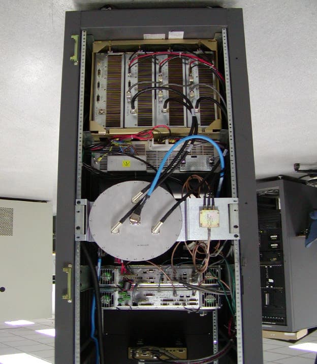
MNT0006068662
Mar 18, 2002Paging Station
Equipment Class
PCB - PCS Licensed Transmitter
MNT-PC-US-1
Mar 25, 2001OSMAC Base
Equipment Class
TNB - Licensed Non-Broadcast Station Transmitter
MNT-PTX-150
May 04, 2000Digital Paging Transmitter
Equipment Class
TNB - Licensed Non-Broadcast Station Transmitter