MNT-PTX-150Digital Paging Transmitter
Vytek Inc
Click to zoom
Application Details
- Equipment Class
- TNB - Licensed Non-Broadcast Station Transmitter
- Date of Grant
- May 04, 2000
- Application Purpose
- Original Equipment
- Date of Application
- Mar 29, 2000
- Equipment Note
- Digital Paging Transmitter
- Frequency Range
- 138.00000000 - 174.00000000
- Company
- Vytek Inc
- Country
- United States
Documents & Files
Document Text
Text extracted from the exhibit documents filed with the FCC. Open a document above to read the original.
Users Manual
MNT-PTX-150 SONIK - 1999 PTX150 DIRECT DIGITAL PAGING TRANSMITTER User Manual Sonik Technologies Corporation 310 Via Vera Cruz, Suite 111 San Marcos, CA 92029 USA Phone: 760-752-1011 FAX: 760-752-1411 Email: [email protected] MNT-PTX-150 Doc Ref : 150-100 Issue : 1.00 SONIK - 1999 CONTENTS 1. INTRODUCTION............................................................................... 1 1.1 GENERAL ................................................................................................... 1 1.2 INDICATORS AND CONNECTORS.............................................................. 2 1.2.1FRONT PANEL INDICATORS .................................................................................... 2 Table1.2.1 LED indication of Transmitter status ......................................................................... 2 1.2.2REAR PANEL CONNECTORS AND SOCKETS ........................................................... 3 Table 1.2.2 Rear Panel functions .............................................................................................. 3 Figure 1.2.0 Rear view............................................................................................................. 3 1.3 DESCRIPTION OF OPERATION.................................................................. 4 Figure 1.3.1 Block Diagram of the Paging Transmitter ................................................................ 4 2. SPECIFICATIONS ............................................................................ 6 Table 2.0.1 - Physical Specifications......................................................................................... 6 Table 2.0.2 - General Specifications ......................................................................................... 6 Table 2.0.3 - RF Characteristics...............................................................................................6 3. INITIAL INSTALLATION................................................................... 7 4. CONNECTION TO NETWORK ......................................................... 9 Table 4.0.1 List of the DB37 connector pins. ............................................................................. 9 5. TROUBLE SHOOTING GUIDE....................................................... 10 Table 5.0.1 - Trouble Shooting ............................................................................................... 10 6. USING THE RDK REMOTE TX DIAGNOSTIC PROGRAM............ 10 7. GLOSSARY OF TERMS................................................................. 11 Appendix A: RDK Software User's Guide.......................................... 1 Appendix B: Basic Connection Between Tx and Controller ............. 1 Appendix C: Satellite Link Mode Configuration for External NIU .... 1 MNT-PTX-150 Doc Ref : 150-100 Issue : 1.00 Page : 1 SONIK - 1999 1. INTRODUCTION INTRODUCTION 1.1 GENERAL The SONIK PTX150 Paging transmitter is a state of the art DSP/DDS (Digital Signal Processor/Direct Digital Synthesis) based device capable of generating all paging modulation formats, and is designed as a general purpose transmitter for all speed paging systems. Construction of the transmitter is fully modular. Internally, the case is divided into compartments with PCB’s arranged in modules, all interconnected by plug/sockets. All modules can be replaced without the use of a soldering iron. Replacement modules do not require alignment or tuning. The SONIK PTX150 transmitter incorporates a universal AC supply and can also operate from a single DC supply for battery back up operation. Software permits the option of ”Hot standby” with auto changeover initiated by software selectable fault conditions. The SONIK PTX150 transmitter is designed for 100% duty cycle at up to 55 ° C ambient conditions amd utilizes advanced cooling technology to maintain very low power transistor junction temperatures. This approach means assures ultra reliable power amplifier performance. The power amplifier temperature is monitored and if the temperature rises above a preset amount (35 ° C), the diagnostics system is alerted and the fan and cooling system is activated. The transmitter is protected by over temperature feedback control to the PA drive input and also incorporates auto fold back for high VSWR conditions. An external frequency reference input is designed to handle standard reference sources and will lock the transmitter to the external reference. An internal ± 1 PPM TCXO (Temperature Compensated Crystal Oscillator) is provided as standard if no external reference is available. In POCSAG wide area systems, the carrier can be ”dithered” by what is known as a ”Black noise” algorithm, to minimize cancellation of equal amplitude carriers from adjacent transmitters. This technique has been used for at least 12 years and is superior to the Carrier offset method. High stability carriers are unnecessary for the carrier dithering technique. For high speed ERMES and FLEX systems, the carrier can be offset in 1Hz steps. MNT-PTX-150 Doc Ref : 150-100 Issue : 1.00 Page : 2 SONIK - 1999 1.2 INDICATORS AND CONNECTORS INTRODUCTION 1.2.1 FRONT PANEL INDICATORS Table 1.2.1 illustrates the front panel diagnostic LEDs. Each LED shows the status of selected functions of the transmitter. In the following figure, the ”CONSOLE” connector acts as the standard RS232 interface for local programming. LEDFUNCTION POWERIndicates that +24VDC is available from the Power supply. TX ONTransmitter is transmitting RF power. LOW POWERRF output is below alarm threshold set in software. HIGH VSWRAntenna port matching is out of specifications set in software. FAULTGlobal fault condition in the transmitter. Refer to ‘Trouble shooting Guide’ in the handbook. FRONT RS232 ACTIVEIndicates that the front panel RS232 port is in use. Table1.2.1 LED indication of Transmitter status MNT-PTX-150 Doc Ref : 150-100 Issue : 1.00 Page : 3 SONIK - 1999 1.2.2 REAR PANEL CONNECTORS AND SOCKETS CONNEC…
Text truncated - open the document above for the full version.
Cover Letter(s)
MNT-PTX-150 List of Exhibits Applicant:Sonik Technologies Corporation Equipment:MNT-PTX-150 Exhibits: ALocation and Format of Label BRegulatory Compliance Report and Technical Report CDeclaration of Conformance DUser Manual and Circuit Description EAlignment and Active Components FBlock Diagrams GSchematic Diagrams IPhotographs JEmission Test Data and Report from EESI
ID Label/Location Info
MNT-PTX-150 1. Exhibit A FCC Identifier Label The label shown below shall be attached to the bottom of the rear panel in the location indicated. The type size is eight-point. FCC ID label Location of label is below the “External Frequency” BNC jack and directly to the left of the “LIU” and “RS-232” connectors on the rear panel. The label is to be placed as not to obstruct any of the other labels or markings.
Internal Photos
MNT-PTX-150Sonik Technologies Corporation Photos of Product MNT-PTX-150: Front Panel MNT-PTX-150Sonik Technologies Corporation Top View with Cover On MNT-PTX-150Sonik Technologies Corporation Front View MNT-PTX-150Sonik Technologies Corporation Rear View MNT-PTX-150Sonik Technologies Corporation Driver and Output Assemblies MNT-PTX-150Sonik Technologies Corporation Power Supply MNT-PTX-150Sonik Technologies Corporation Digital and Modulation PCBs MNT-PTX-150Sonik Technologies Corporation Photos of MTX-150 Printed Circuit Boards: Digital Processing and Modulation PC Boards No components are mounted on opposite side of this circuit board. MNT-PTX-150Sonik Technologies Corporation Control Input / Output PC Board No components are mounted on opposite side of this circuit board. MNT-PTX-150Sonik Technologies Corporation Front Display PC Board No components are mounted on opposite side of this circuit board. MNT-PTX-150Sonik Technologies Corporation 30 Watt Driver PC Board No components are mounted on opposite side of this circuit board. MNT-PTX-150Sonik Technologies Corporation 100 Watt Power Amplifier PC Board No components are mounted on opposite side of this circuit board. MNT-PTX-150Sonik Technologies Corporation Power Control PC Board No components are mounted on opposite side of this circuit board.
Parts List/Tune Up Info
MNT-PTX-150 ! "#$%&'()*!+, )-.$"/%))0- .1%2$0/0$) MNT-PTX-150 3 1. Main-Board Tune-up Procedures Adjustments )45'678879:;<'=>?85 8:@=@'=45':;=5A;>8 >BCD@=E5;=@F'')45@5 E>G'7;8G'?5'>BCD@=5B ?G'HD>8:6:5B 585I=A7;:I'@5AJ:I5 K5A@7;;58'D@:;< I>8:?A>=5B'=5@= 5HD:KE5;=F Reference Designator Function VR1Power Set VR2Power Control RV1Lock Detect Active Components L /7B5E'M5I7B5A'"5I=:7;N O7EK7;5;=PD;I=:7; Q!'/7B5E Q+/7B5E'R'%S#'(A7I5@@7A QTM>A8:;<=7;'%S#'MA:J5A@ M"('>;B'/7BD8>=:7;'"5I=:7;N O7EK7;5;=PD;I=:7; )O*#!%;=5A;>8'-565A5;I5'#@I:88>=7A Q!/>:;'/:IA7KA7I5@@7A QT-"3U3'%;=5A6>I5 QU00(-#/'67A'Q! Q+L'QVL'Q!WM"('/7BD85 /*!P:A@='/:X5A /*3"5I7;B'/:X5A Y!'UVFT'/Z['7@I:88>=7A Q3L'Q\L'Q!VM58>G'O7AA5I=:7; QWL'Q!,L'Q!!L'Q!3L'Q!+L (795A'"DKK8G -5<D8>=:7; Q!TL'Q!] MA:J5A'.@@5E?8GN O7EK7;5;=PD;I=:7; Y3W(A5^MA:J5A MNT-PTX-150 U YU,MA:J5A QTVL'Q!\"DKK8G'-5<D8>=:7; #D=KD='.@@5E?8GN O7EK7;5;=PD;I=:7; O(1!MA:J5'"K8:==5A Y!L'Y3P:;>8'#D=KD='M5J:I5@ O(13(795A'O7E?:;5A 3F'(O'O#/'"5==:;<@ "585I=' ” 17I>8"5=DK ” L' =45;' ” O7EE@' "5=DK ” _> B:>87<'?7X'9:88'K7K'DK_ `7D'I>;'I7;6:<DA5'=45'87I>8'O#/':;'=45 B:>87<'?7X'>?7J5_ • O#/!_O#/3FFF • a>DB'->=5 • (>A:=G • M>=5'a:=@ • "=7K'a:= • P879'O7;=A78_Z>AB9>A5'#A'"76=9>A5_ -M&' @DKK7A=' A5E7=5' B:>8' :;' >;B' E7;:=7A 9:=4'>'/#M0/'@5= MNT-PTX-150 T • -D;;:;<' ZGK5A' )5AE:;>8' :;' b:;B79@' 7A (O(1Q"' KA7<A>EL' >;B' @585I=' =45' O#/ I7;;5I=5B'=7'/#M0/L'@5='>@'?5879N c .)",d!_/#M0/'>D=7'>;@95A c .)RM,_/#M0/':<;7A5'M)-_ c .)R&,_/#M0/'I>;I58'6879'I7;=A78_ c .)Rb,_">J5'IDAA5;='@5==:;<@_ MNT-PTX-150 + 3. Modem Commands and Modem Responses "585I=:;<' ” /7B5E' "5=DK ” '_:;I8DB:;< @5==:;<_ MNT-PTX-150 ] 4. Dialer Configuration ''"585I=:;<' ” M:>85A' "5=DK ” _:;I8DB:;< @5==:;<N • />X:EDE'-5=A:5@ • ):E5'a5=955;'-5=A:5@ • M:>8'I7;;5I='=:E57D= • Z>G5@'I7EE>;B'=:E57D= • .?7A=' 7;' aQ"`_.?7A=' 7;' e#%O0_.?7A=' 7;' $# O.--%0-_.?7A='7;'$#'M%.1)#$0_'.?7A='7;'0--#- MNT-PTX-150 \ 5. LINK MODEM SETTINGS fghijkK_l_ • .8>AE'>;B'.D=7'-5K7A=_ c (47;5'$DE?5A c )7;5'M:>8:;< c $DE?5A'76'-5=A:5@ c ):E5'a5=955;'-5=A:5@ • -5E7=5'B:>8'>;B'E7;:=7A_ c 0;>?85'.D=7'.;@95A c $DE?5A'76'-:;<@ c O7;6:<DA5'"=A:;< • .BBA5@@S%M • a>DB'->=5 MNT-PTX-150 V • .D=7'"=>=D@'-5K7A= c 0;>?85 c (5A:7B 6. Transmitter Settings • )X' PA5H_' @:X=55;' 6A5HD5;IG' I4>;;58' I>; ?5' KA5' @5=' ' >;B' >' I5A=>:;' I4>;;58' 9:88 ?5'J>8:B'?>@5B'7;'=45'67DA'6A5HD5;IG @585I='(%$'7;'=45'A5>A'K>;58'76 =A>;@E:==5A@_ • )X'O7;=A78_-P'I7;=A78'B>=>_ • /7B5E_8:;m'/#M0/'@5==:;<@_ • .8>AE@_.8>AE'A>;<5'@5==:;<@_ • QKB>=5_9A:=5' =45' B>=>' I4>;<5B' :;=7 =A>;@E:==5A@_ • -0.M_A5>B'=45'IDAA5;='@5==:;<@':; =A>;@E:==5A@_ • M:><;7@=:I@n_"586' =5@=' :;I8DB:;<' P7A9>AB (795A'L'e"b-'LODAA5;=')5EK5A>=DA5'5=I_ • M:>8' -5E7=5N' B:>8' ;DE?5A' 76' > =A>;@E:==5A_ • 17>B_87>B' >' B7IDE5;=' @5==:;<@' :;=7' > =A>;@E:==5A_ • ">J5_@>J5'IDAA5;='@5==:;<':;=7'>'6:85_ • Z58K_458K'B7IDE5;=@'>?7D='-M&'_ MNT-PTX-150 W 1 .5.1 Tx Freq O8:Im' ” )X' PA5H ” ' ?D==7;_>;B' :;KD=' -P 6A5HD5;IG':;=7'B:665A5;='I4>;;58@ MNT-PTX-150 !, 1.5.2 Tx Control O8:Im' ” )X'O7;=A78 ” '?D==7;_ • />@=5A'-P'#D=KD=ob>==@nN'3+' – '!!,'b>==@_ • .?@78D=5' M58>G' O7AA5I=:7;' oD@5InN' ,' – 'T, E@ • PA5HD5;IG'#66@5='oZ[nN'^U,,,Z['_'pU,,,Z[ • 0X=5A;>8' PA5HF' "7DAI5N' Q@5' 5X=5A;>8 PA5HD5;IG'7A':;=5A;>8'7;5_ • (78>A:=G_ c ())'(7@:=:J5'0B<5_ c M>=>'O87Im'$5<>=:J5'0B<5_ c %;J5A='M>=> MNT-PTX-150 !! • M56>D8='KA7=7I78o!n_(A7=7I78!'I47@5; 94:85' (:;!' 76' MaU\' I7;;5I=5B' =7' 2A7D;B o179'15J58n • M56>D8=' KA7=7I78' o3n_' (A7=7I783' I47@5; 94:85'(:;!'76'MaU\'B5=>I45B'6A7E 2A7D;BoZ:<4'15J58n'_ • 0;>?85'.D=7'M5=5I= • )DA;'#66'):E5o"5I@n_.6=5A'@:<;>8@'>A5'@5;= 7D='L'=45'=:E5'=A>;@E:==5A'A5E>:;'@5;B:;< I>AA:5A_ 1.5.3 Alarms Settings • -P' (795A' .8>AEo9>==@n' _=45' 4:<4' >;B' 879 K795A'8:E:=_ • Z:<4' e"b-_4:<4' e"b-' 8:E:=' >;B' ID==:;< 8:E:=_ MNT-PTX-150 !3 • )5EK5A>=DA5' oB5<On_/>@=5A' OD=' #D=' )5EK _-5@5='>;B'.8>AE')5EK_ • e78=><5' .8>AEoJ78=@n_' Z:<4' J78=><5' >;B 879'J78=><5'A>;<5_ • Z:<4'ODAA5;=o.EK@n_'OD='#D='IDAA5;='8:E:= >;B'>8>AE'8:E:=_ MNT-PTX-150 !U 1.5.4 Help O8:Im' ” Z58K ” '?D==7;'_ MNT-PTX-150 !T 3.6 Real Time Diagnostics Q@5A' I>;' A5>8:[5' =45' A5>8' =:E5 E7;:=7A:;<'7;'=45'6D;I=:7;'76 =A>;@E:==5A@_8:m5'-P (795A_e"b-_)5EK5A>=DA5_("Q'e#1)"_(. ODAA5;=_MA:J5A' (795A_a8D5' >A5>' @479@' 879 >8>AE:;<_2A55;' >A5>' @479@' $7AE>8_-5B' >A5> @479@'4:<4'>8>AE_ MNT-PTX-150 !+ O8:Im' ” P>D8=' -5K7A= ” ' =7' A5>B' 6>D8= :;67AE>=:7;_
Test Report
MNT-PTX-150 Page Sonik Technologies Corp. 1 Regulatory Compliance Report EQUIPMENT IDENTIFICATION FCC ID: MNT-PTX-150 Applicable FCC Parts 22, 90 NAMEPLATE DRAWING ATTACHED, EXHIBIT A. LOCATION AS PER LABEL DRAWING(S) DATE OF REPORT March 13, 2000 Supervised By: John Sonnenberg CEO/Chief Technical Officer Sonik Technologies Corporation MNT-PTX-150 Page Sonik Technologies Corp. 2 Table of Contents 1. STATEMENTS.............................................................. 3 1.1INFORMATION TO USER(CFR 15.21).......................................................................................................... 3 1.2SPECIAL ACCESSORIES (CFR 15.27(a)) ..................................................................................................... 3 1.3Spectrum Efficiency Certification(CFR 2.203(j)(i))......................................................................................... 3 1.4Programmability (CFR 90.203(g)).................................................................................................................... 3 2. DECLARATION OF CONFORMITY (CFR 2.1071).................................. 4 3. STANDARD TEST CONDITIONS AND ENGINEERING PRACTICES...................... 7 4. TEST RESULTS............................................................ 8 4.1RF Power Output .............................................................................................................................................. 8 4.2VOICE MODULATION CHARACTERISTICS – ............................................................................................ 9 4.3OCCUPIED BANDWIDTH............................................................................................................................ 10 4.3.1 Total Channel Power.....................................................12 4.3.2 Occupied Bandwidth, 512 Baud POCSAG....................................12 4.3.3 Occupied Bandwidth, 2400 Baud POCSAG....................................13 4.3.4 Occupied Bandwidth, 3200 Baud ERMES 4-Level.............................13 4.3.5 Occupied Bandwidth, 6400 Baud ERMES 4-Level.............................14 4.3.6 Occupied Babdwidth, 6400 Baud FLEX 4-Level..............................14 4.3.7 Occupied Bandwidth, 3200 Baud Flex 4 Level..............................15 4.3.8 Occupied Bandwidth, 1600 Baud FLEX 2-Level..............................15 4.4TRANSMITTER CONDUCTED SPURIOUS EMISSIONS........................................................................... 16 4.5FIELD STRENGTH OF RADIATED SPURIOUS EMISSIONS .................................................................... 18 4.6FREQUENCY STABILITY - TEMPERATURE VARIATION ...................................................................... 20 4.7FREQUENCY STABILITY - VOLTAGE VARIATION ................................................................................ 22 4.8NECESSARY BANDWIDTH AND EMISSION BANDWIDTH................................................................... 23 4.9TRANSIENT FREQUENCY BEHAVIOR ..................................................................................................... 24 4.9.1 TRANSIENT FREQUENCY BEHAVIOR, NO MODULATION.............................25 4.9.2 TRANSIENT FREQUENCY BEHAVIOR, 512 Baud..................................26 4.9.3 TRANSIENT FREQUENCY BEHAVIOR, 2400 Baud.................................27 4.9.4 TRANSIENT FREQUENCY BEHAVIOR, 6400 Baud, 4-Level........................28 4.10TESTIMONIAL AND STATEMENT OF CERTIFICATION:.................................................................. 29 MNT-PTX-150 Page Sonik Technologies Corp. 3 1. Statements 1.1 INFORMATION TO USER(CFR 15.21) The user’s manual or instruction manual for an intentional radiator shall caution the user that changes or modifications not expressly approved by the party responsible for compliance could void the user’s authority to operate the equipment. 1.2 SPECIAL ACCESSORIES (CFR 15.27(a)) No special equipment or accessories are required to be supplied with the unit or by the user to ensure compliance with the applicable standards. 1.3 Spectrum Efficiency Certification(CFR 2.203(j)(i)) This products transmitter is factory programmed (non-user programmable), for use on 25kHz spaced channels. The only data transmission capability it has is to send one-way paging data, which is exempt from the 4800bps/6.25kHz efficiency requirements for data per 90.203(j)(7). 1.4 Programmability (CFR 90.203(g)) The user cannot change the frequency step size or bandwidth of the product using the operator’s controls. MNT-PTX-150 Page Sonik Technologies Corp. 4 2. Declaration of Conformity (CFR 2.1071) The applicant is aware that it is the responsible party as defined per CFR 2.909. The applicant has tested and confirmed that the product referenced in this application conforms to the applicable technical standards within the CFR Part 15, provided that no un-authorized change to the equipment is made. The applicant warrants that each product marketed is identical to the unit tested for conformance. The applicant maintains the records of the compliance testing of the product. All units produced are tested to ensure that they have the same characteristics as the unit tested. MNT-PTX-150 Page Sonik Technologies Corp. 5 LIST OF GENERAL INFORMATION REQUIRED FOR CERTIFICATION IN ACCORDANCE WITH FCC RULES AND REGULATIONS, VOLUME II, PART 2 AND PARTS 22 and 90. Sub-part 2.1033(C1) : NAME AND ADDRESS OF APPLICANT: SONIK TECHNOLOGIES CORPORATION 310 VIA VERA CRUZ, SUITE 111 SAN MARCOS, CA 92069 VENDOR: APPLICANT 2.1033(C2) : FCC ID: MNT-PTX-150 MODEL NO:PTX-150 2.1033(C3): User manual: See attached exhibit. 2.1033(C4): TYPES OF EMISSION: 16K0F1D 2.1033(C5): FREQUENCY RANGE, MHz: 138MHz to 174MHz 2.1033(C6): POWER RATING, Watts: 100W (programmable and set at factory) 2.1033(C7): MAXIMUM POWER RATING, Watts: 100 2.1033(C8): VOLTAGES & CURRENTS IN ALL ELEMENTS IN FINAL R. F. STAGE, INCLUDING FINAL TRANSISTOR OR SOLID STATE DEVICE: COLLECTOR…
Text truncated - open the document above for the full version.
Contact Information
Applicant
Ronald J. Weber(Vice President)
Technical Contact
Sonik Technologies CorporationJohn R Sonnenberg
[email protected]760-752-1011
310 Via Vera Cruz #111 · San Marcos, California · United States
Non-Technical Contact
Sonik Technologies CorporationJohn R Sonnenberg
[email protected]760-752-1011
Test Firm
Nemko USA, Inc.Rhonda Saxon
Technical Specifications
| # | Rule Parts | Frequency Range | Power Output | Emission | Tolerance |
|---|---|---|---|---|---|
| 1 | 22,90 | 138 MHz - 174 MHz | 100 W | 16K0F1D | 1.0000000000 ppm |
Other Applications from Vytek Inc

MNT-PC-UC-2
Dec 21, 2005Base Station Irrigation Control Module
Equipment Class
TNB - Licensed Non-Broadcast Station Transmitter
MNT-G2BT
Jul 15, 2002Sonik G2BT Base Transmitter
Equipment Class
PCB - PCS Licensed Transmitter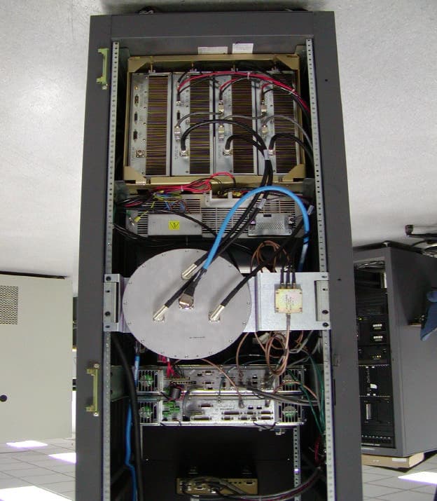
MNT0006068662
Mar 18, 2002Paging Station
Equipment Class
PCB - PCS Licensed Transmitter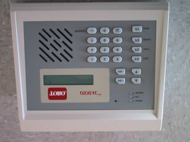
MNT-PC-UC-1
Mar 29, 2001OSMAC Base
Equipment Class
TNB - Licensed Non-Broadcast Station Transmitter
MNT-PC-US-1
Mar 25, 2001OSMAC Base
Equipment Class
TNB - Licensed Non-Broadcast Station Transmitter