MNT0006068662Paging Station
Vytek Inc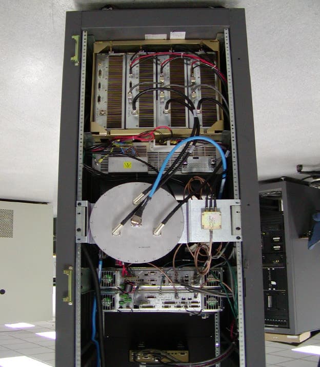
Click to zoom
Application Details
- Equipment Class
- PCB - PCS Licensed Transmitter
- Date of Grant
- Mar 18, 2002
- Application Purpose
- Original Equipment
- Date of Application
- Mar 18, 2002
- Equipment Note
- Paging Station
- Frequency Range
- 940.00000000 - 941.00000000
- Company
- Vytek Inc
- Country
- United States
Documents & Files
Document Text
Text extracted from the exhibit documents filed with the FCC. Open a document above to read the original.
Users Manual
Power Amplifier Serial I/F Spec. 1 Version 1.62 Power Amplifier Serial Interface Version 1.62 Requirements Specification Sonik Technologies Corporation Sonik Technologies Corporation 2310 Cousteau Court Vista, CA 92083 Ph: 760-536-1000 Fax: 760-536-1025 Power Amplifier Serial I/F Spec. 2 Version 1.62 Table of Contents 1. Introduction..................................................................................................................3 1.1 Version Control........................................................................................................3 1.2 Scope........................................................................................................................3 1.3 Overview..................................................................................................................3 2. Power Amplifier...........................................................................................................4 2.1 Status & Control......................................................................................................4 2.2 Non-volatile read/write memory..............................................................................5 3. Microprocessor Interface.............................................................................................6 3.1 SPI BUS ID..............................................................................................................6 3.2 Serial Communication Description..........................................................................7 3.3 SPI Bus Interface.....................................................................................................7 3.4 Power Amplifier Device ID.....................................................................................8 3.5 SPI Electrical Considerations..................................................................................9 3.6 Serial Communication Format.................................................................................9 3.7 SPI Session Protocol..............................................................................................10 3.7.1 Power Amplifier DeviceID 0 transfer protocol.............................................11 3.7.2 Power Amplifier DeviceID 1 transfer protocol.............................................12 3.7.3 Power Amplifier DeviceID 2 transfer protocol.............................................12 3.7.4 Power Amplifier DeviceID 3 transfer protocol.............................................12 3.7.5 Power Amplifier DeviceID 4 transfer protocol.............................................12 Power Amplifier Serial I/F Spec. 3 Version 1.62 1. Introduction 1.1 Version Control Date Author Revision Comment 12/20/00 Welte 1.00 Initial Revision 12/21/00 Welte 1.10 Added more clarity to section 2.4 and changed Figure 2-1 to specify host as Master and size of transaction. 1/4/01 Welte 1.20 Redefined chip select, device ID mechanism. Made some changes to timing diagrams. 1/9/01 Welte 1.30 Changes made in accordance to design review, namely remove the –RackEnable signal, specify backplane values, make some error corrections. 1/10/01 JS 1.40 Elaborated on hardware issues. 3/30/01 G. Nakao 1.41 6/6/01 G. Nakao 1.42 SPI Refinements 6/7/01 RMS 1.61 Further clarifications 9/12/01 J.Briggs 1.62 SPI Timing changes 1.2 Scope This document is a technical description of the RF Power Amplifier Serial Peripheral Interface (SPI) requirements. 1.3 Overview The Power Amplifiers operate at approximately 133 watts average power, and will be combined in parallel to achieve 400 watts average power, or 1200 watts peak power. Amplifier status and configuration is done via the SPI interface. The amplifier section is comprised of 3 modules. Two SPI interface connectors are to be located on the rear of each amplifier module. The SPI interface is routed to each individual amplifier within the amplifier by daisy chain wiring. In the event of an amplifier failure, the remaining amplifiers continue to operate, providing continuous performance and soft fail operation. Failed amplifiers indicate their status via the SPI interface. The Power Amplifier must be capable of collecting and sending over the serial bus amplifier status including: temperature forward power reflected power attenuator level phase setting Power Amplifier Serial I/F Spec. 4 Version 1.62 DC supply voltage DC supply current fan status internal self- test result amplifier model number 2. Power Amplifier 2.1 Status & Control The Power Amplifier has status & control information as defined in Table 2.1: Power Amplifier Serial I/F Spec. 5 Version 1.62 Description No. of Bits Definition Read/Write Temperature 8 0 = 0C 255 = -1C 206 = -50C 100 = +100C Read only Forward Power 8 0 = 0 Watts 1 = 1 Watts 255 = 255 Watts Read only Reflected Power 8 0 = 0 Watts 1 = 1 Watts 255 = 255 Watts Read only DC Supply Voltage 8 0 = 0 Volts 255 = 30V Read only DC Supply Current 8 0 = 0 Amps 255 = 40 amps Read only Fan Fail Alarm 1 0 = Normal, 1 = Alarm Occurred Read only Amplifier Online 1 0= offline, 1=enabled Read/Write Amplifier Reset 1 0 = Normal, 1 = Reset Occurred Read/Write Reverse Power Shutdown 1 0 = Normal, 1 = Shutdown Occurred Read/Write Amplifier Overdrive Alarm 1 0 = Normal, 1 = Alarm Occurred Read/Write Thermal Alarm 1 0 = Normal, 1 = Alarm Occurred Read/Write Amplifier Overdrive Shutdown 1 0 = Normal, 1 = Shutdown Occurred Read/Write Thermal Alarm Shutdown 1 0 = Normal, 1 = Shutdown Occurred Read/Write Phase Control 8 -128 = -20 degrees min (in 40 steps) 0 = 0 degrees +127 = +20 degrees min (in 40 steps) Write Only Attenuation Level 8 0 = -2 dB min (in 40 steps) 63 = No attenuation 127 = +2 dB min (in 40 steps) Write Only Serial Number 256 Read only Table 2-1 2.2 Non-volatile read/write In addition, the Power Amplifier contains 256 bytes of non-volatile read/write memory for storing phase control and attenuation levels for various channel frequencies. The manufac…
Text truncated - open the document above for the full version.
Users Manual
RF-Baton! Transmitter Controller Installation and Operation Issue Date: June 1999 6880497G01-B Series: Wireless Messaging System System Version: Two-Way 3.0 Software Version: 1.7.0 for the RF-O!™ Paging Station TM RF-Baton! Transmitter Controller Installation and Operation Issue Date: June 1999 6880497G01-B Series: Wireless Messaging System System Version: Two-Way 3.0 Software Version: 1.7.0 for the RF-O!™ Paging Station TM RF-Baton! Transmitter Controller Installation and Operation June 19996880497G01-Biii 10/28/97 Foreword General Information The information in this manual has been reviewed for accuracy. However, no responsibility is assumed for inaccuracies. Motorola reserves the right to make changes to any products discussed herein. The information in this document is subject to change without notice. Motorola assumes no liability for hardware or software damage or loss of data because of errors or omissions in this manual. Motorola does not assume any liability arising from the application or use of any products or circuits described herein. Neither does Motorola convey any license under its patents or right of others. Refer questions concerning the contents of this manual or requests for related circuit board information to the following location: Motorola, Inc. Paging Systems Group Multimedia Publications Department 5401 North Beach St., MS E230-A Fort Worth, TX 76137-2794 or telephone:(817) 245-4260 To access on-line electronic information (BBS) for service notices and the latest software releases, call the Paging One-Call-Support Center. To request additional manuals or parts, please contact the Motorola Americas Parts Division: telephone:(800) 422-4210 facsimile:(847) 538-8198 To request a part number, contact the Parts Identification Group: telephone:(847) 538-0021 For Motorola Infrastructure and communicator test equipment, contact the Motorola Test Equipment Center: telephone:(800) 505-8378 ForewordRF-Baton! Transmitter Controller Installation and Operation iv6880497G01-BJune 1999 Global Service Organization Motorola provides Infrastructure and communicator technical support through authorized or company-owned Service Centers. Motorola also provides service for communicators on a contract basis. For contract service information, please contact your local Motorola representative or the Paging One-Call-Support Center: Motorola, Inc. Paging One-Call-Support Center 5401 North Beach St., MS E112 Fort Worth, TX 76137-2794 telephone:(800) 520-7243 or (817) 245-4663 facsimile:(817) 245-2141 Service Training Motorola, through its Advanced Messaging Technical Training Group in Fort Worth, Texas, offers courses on communicators, messaging switches, transmitters, and receivers. These courses are taught on the site or at a customer ’s location. Students learn to install, configure, and maintain Motorola messaging systems. The classrooms at Motorola are equipped to ensure hands-on experience in practical lab exercises. Training courses range from a basic introduction to communicators and messaging systems to customized classes on specific systems and large system applications. To obtain a course catalog or scheduling information, please call (817) 245-2184 or (800) 724-3588 and ask for the training coordinator. RF-Baton! Transmitter Controller Installation and OperationForeword June 19996880497G01-Bv Computer Software Copyrights The Motorola products described in this manual might include copyrighted Motorola computer software stored in semiconductor memories and other media. Laws in the United States and other countries preserve for Motorola certain exclusive rights for copyrighted computer programs, including the exclusive right to copy or reproduce in any form the copyrighted computer software. Accordingly, any copyrighted Motorola computer software contained in the Motorola products described in this manual cannot be copied or reproduced in any manner without the express written permission of Motorola. Furthermore, the purchase of Motorola products does not grant, either directly or by implication, estoppel, or otherwise, any license under the copyrights, patents or patent applications of Motorola, except for the normal, nonexclusive, royalty-free license to use that arises by operation of law in the sale of a product. Trademarks Motorola, the Motorola logo, and Nucleus Reg. U.S. Pat. and TM. Off, Motorola, Inc. Paging One-Call-Support, Choreographer!, FLEX, ReFLEX, InFLEXion, RF-Audience!, RF-A!, RF-Baton!, RF-B!, RF-Conductor!, RF-C!, RF-Orchestra!, RF-O!, Wireless Message Gateway, and WMG-Administrator! are trademarks of Motorola, Inc. Procomm Plus is a registered trademark of Datastorm Technologies, Inc. TORX is a registered trademark of Camcar Division of Textron, Inc. Trademarks contained herein are the acknowledged property of their respective owners. ForewordRF-Baton! Transmitter Controller Installation and Operation vi6880497G01-BJune 1999 Important Safety Information The installation, maintenance, and/or operation of this equipment may present potentially unsafe conditions, including, but not limited to, electrical shock, improper voltage to components, and improper operation that can cause personal injury, death or damage to property. Read Instructions: Read all the safety instructions before operating the equipment. Retain these safety instructions for future reference. Specialized procedures and instructions are required and must be followed. Also, all applicable safety procedures, such as Occupational, Safety, and Health Administration (OSHA) requirements, National Electric Code Requirements, local code requirements, safe working practices, and good judgement must be used by personnel. Heed Admonitions: Adhere to all warnings on the equipment and in the operating instructions. Follow all operating and use instructions. Two safety admonitions are used in this instruction manual to indicate: •Equipment damage– •Personal injury or injury that may result in death– Mount…
Text truncated - open the document above for the full version.
Users Manual
RF-Orchestra! Transmitter Installation and Operation Issue Date: July 1999 6880493G02-C Series: Wireless Messaging System System Version: WMS 3.0 Software Version: 2.0 TM for the RF-O!™ Paging Station RF-Orchestra! Transmitter Installation and Operation Issue Date: July 1999 6880493G02-C Series: Wireless Messaging System System Version: WMS 3.0 Software Version: 2.0 for the RF-O!™ Paging Station TM Choreographer!™ Network Manager Installation and Operation August 19996880492G07-D Preliminaryv 07/01/98 Foreword General Information The information in this manual has been reviewed for accuracy. However, no responsibility is assumed for inaccuracies. Motorola reserves the right to make changes to any products discussed herein. The information in this document is subject to change without notice. Motorola assumes no liability for hardware or software damage or loss of data because of errors or omissions in this manual. Motorola does not assume any liability arising from the application or use of any products or circuits described herein. Neither does Motorola convey any license under its patents or right of others. Refer questions concerning the contents of this manual or requests for related circuit board information to the following location: Motorola, Inc. Paging Systems Operations Technical Communications Department 5401 North Beach St., MS E230-A Fort Worth, TX 76137-2794 or telephone:(817) 245-4222 To access on-line electronic information for service notices and the latest software releases, call the Paging One-Call-Support . To request additional manuals or parts, please contact the Motorola Accessories and After Market Division: telephone:(800) 422-4210 facsimile:(847) 538-8198 To request a part number, contact the Parts Identification Group: telephone:(847) 538-0021 For Motorola Infrastructure and communicator test equipment, contact the Motorola Test Equipment Center: telephone:(800) 505-8378 ForewordChoreographer!™ Network Manager Installation and Operation vi6880492G07-D PreliminaryAugust 1999 Global Service Organization Motorola provides Infrastructuretechnical support through authorized or company-owned Service Centers. Motorola also provides service for infrastructure products on a contract basis. For contract service information, please contact your local Motorola representative or the Paging One-Call-Support Center: Motorola, Inc. Paging One-Call-Support 5401 North Beach St., MS E112 Fort Worth, TX 76137-2794 telephone:(800) 520-7243 (Domestic) (817) 245-4663 (International) facsimile:(817) 245-2141 electronic mail:[email protected] (to have Technical Support contact you) web access:www.pagingsystems.com Service Training To obtain a course catalog or scheduling information, contact the training coordinator: telephone:(817) 245-2184 (800) 724-3588 electronic mail:[email protected] Computer Software Copyrights The Motorola products described in this manual might include copyrighted Motorola computer software stored in semiconductor memories and other media. Laws in the United States and other countries preserve for Motorola certain exclusive rights for copyrighted computer programs, including the exclusive right to copy or reproduce in any form the copyrighted computer software. Accordingly, any copyrighted Motorola computer software contained in the Motorola products described in this manual cannot be copied or reproduced in any manner without the express written permission of Motorola. Furthermore, the purchase of Motorola products does not grant, either directly or by implication, estoppel, or otherwise, any license under the copyrights, patents or patent applications of Motorola, except for the normal, nonexclusive, royalty-free license to use that arises by operation of law in the sale of a product. Choreographer!™ Network Manager Installation and OperationForeword August 19996880492G07-D Preliminaryvii Trademarks Motorola, SuperStream, and FLEX are trademarks of Motorola, Inc. Other trademarks are noted as such throughout this document. Antares and Dialogic are trademarks of Dialogic Corporation. HP, Hewlett Packard, OpenView, and LaserJet are registered trademarks of Hewlett-Packard Company. Intel is a registered trademark, and 80286 and Pentium are trademarks of Intel Corporation. UnixWare is a registered trademark of Novell, Inc. Solaris, Sun, Java and Solaris are registered trademarks of Sun Microsystems, Inc. Static Stop is a registered trademark of Barco Chemical Products. Informix is a registered trademark of Informix Software, Inc. SPARC is a trademark of SPARC International. WMtp is a trademark of Glenayre. X Window System is a trademark of the Massachusetts Institute of Technology. Trademarks contained herein are the acknowledged property of their respective owners. Important Safety Information The installation, maintenance, and/or operation of this equipment may present potentially unsafe conditions, including, but not limited to, electrical shock, improper voltage to components, and improper operation that can cause personal injury, death or damage to property. Read Instructions: Read all the safety instructions before operating the equipment. Retain these safety instructions for future reference. Specialized procedures and instructions are required and must be followed. Also, all applicable safety procedures, such as Occupational, Safety, and Health Administration (OSHA) requirements, National Electric Code Requirements, local code requirements, safe working practices, and good judgement must be used by personnel. Heed Admonitions: Adhere to all warnings on the equipment and in the operating instructions. Follow all operating and use instructions. Two safety admonitions are used in this instruction manual to indicate: •Equipment damage– CAUTION This safety admonition applies to an operating or maintenance procedure, practice or condition which, if not strictly observed, could result in damage to the equipment or database. ForewordChoreographer!™ Network M…
Text truncated - open the document above for the full version.
Users Manual
Power Amplifier Serial I/F Spec. 1 Version 1.62 Power Amplifier Serial Interface Version 1.62 Requirements Specification Sonik Technologies Corporation Sonik Technologies Corporation 2310 Cousteau Court Vista, CA 92083 Ph: 760-536-1000 Fax: 760-536-1025 Power Amplifier Serial I/F Spec. 2 Version 1.62 Table of Contents 1. Introduction..................................................................................................................3 1.1 Version Control........................................................................................................3 1.2 Scope........................................................................................................................3 1.3 Overview..................................................................................................................3 2. Power Amplifier...........................................................................................................4 2.1 Status & Control......................................................................................................4 2.2 Non-volatile read/write memory..............................................................................5 3. Microprocessor Interface.............................................................................................6 3.1 SPI BUS ID..............................................................................................................6 3.2 Serial Communication Description..........................................................................7 3.3 SPI Bus Interface.....................................................................................................7 3.4 Power Amplifier Device ID.....................................................................................8 3.5 SPI Electrical Considerations..................................................................................9 3.6 Serial Communication Format.................................................................................9 3.7 SPI Session Protocol..............................................................................................10 3.7.1 Power Amplifier DeviceID 0 transfer protocol.............................................11 3.7.2 Power Amplifier DeviceID 1 transfer protocol.............................................12 3.7.3 Power Amplifier DeviceID 2 transfer protocol.............................................12 3.7.4 Power Amplifier DeviceID 3 transfer protocol.............................................12 3.7.5 Power Amplifier DeviceID 4 transfer protocol.............................................12 Power Amplifier Serial I/F Spec. 3 Version 1.62 1. Introduction 1.1 Version Control Date Author Revision Comment 12/20/00 Welte 1.00 Initial Revision 12/21/00 Welte 1.10 Added more clarity to section 2.4 and changed Figure 2-1 to specify host as Master and size of transaction. 1/4/01 Welte 1.20 Redefined chip select, device ID mechanism. Made some changes to timing diagrams. 1/9/01 Welte 1.30 Changes made in accordance to design review, namely remove the –RackEnable signal, specify backplane values, make some error corrections. 1/10/01 JS 1.40 Elaborated on hardware issues. 3/30/01 G. Nakao 1.41 6/6/01 G. Nakao 1.42 SPI Refinements 6/7/01 RMS 1.61 Further clarifications 9/12/01 J.Briggs 1.62 SPI Timing changes 1.2 Scope This document is a technical description of the RF Power Amplifier Serial Peripheral Interface (SPI) requirements. 1.3 Overview The Power Amplifiers operate at approximately 133 watts average power, and will be combined in parallel to achieve 400 watts average power, or 1200 watts peak power. Amplifier status and configuration is done via the SPI interface. The amplifier section is comprised of 3 modules. Two SPI interface connectors are to be located on the rear of each amplifier module. The SPI interface is routed to each individual amplifier within the amplifier by daisy chain wiring. In the event of an amplifier failure, the remaining amplifiers continue to operate, providing continuous performance and soft fail operation. Failed amplifiers indicate their status via the SPI interface. The Power Amplifier must be capable of collecting and sending over the serial bus amplifier status including: temperature forward power reflected power attenuator level phase setting Power Amplifier Serial I/F Spec. 4 Version 1.62 DC supply voltage DC supply current fan status internal self- test result amplifier model number 2. Power Amplifier 2.1 Status & Control The Power Amplifier has status & control information as defined in Table 2.1: Power Amplifier Serial I/F Spec. 5 Version 1.62 Description No. of Bits Definition Read/Write Temperature 8 0 = 0C 255 = -1C 206 = -50C 100 = +100C Read only Forward Power 8 0 = 0 Watts 1 = 1 Watts 255 = 255 Watts Read only Reflected Power 8 0 = 0 Watts 1 = 1 Watts 255 = 255 Watts Read only DC Supply Voltage 8 0 = 0 Volts 255 = 30V Read only DC Supply Current 8 0 = 0 Amps 255 = 40 amps Read only Fan Fail Alarm 1 0 = Normal, 1 = Alarm Occurred Read only Amplifier Online 1 0= offline, 1=enabled Read/Write Amplifier Reset 1 0 = Normal, 1 = Reset Occurred Read/Write Reverse Power Shutdown 1 0 = Normal, 1 = Shutdown Occurred Read/Write Amplifier Overdrive Alarm 1 0 = Normal, 1 = Alarm Occurred Read/Write Thermal Alarm 1 0 = Normal, 1 = Alarm Occurred Read/Write Amplifier Overdrive Shutdown 1 0 = Normal, 1 = Shutdown Occurred Read/Write Thermal Alarm Shutdown 1 0 = Normal, 1 = Shutdown Occurred Read/Write Phase Control 8 -128 = -20 degrees min (in 40 steps) 0 = 0 degrees +127 = +20 degrees min (in 40 steps) Write Only Attenuation Level 8 0 = -2 dB min (in 40 steps) 63 = No attenuation 127 = +2 dB min (in 40 steps) Write Only Serial Number 256 Read only Table 2-1 2.2 Non-volatile read/write In addition, the Power Amplifier contains 256 bytes of non-volatile read/write memory for storing phase control and attenuation levels for various channel frequencies. The manufac…
Text truncated - open the document above for the full version.
External Photos
S S o o n n i i k k T T e e c c h h n n o o l l o o g g i i e e s s C C o o r r p p o o r r a a t t i i o o n n ITEMS REQUIRED FOR AN FCC CERTIFICATION SUBMITTAL FCC Part 2, Paragraph 2.1033 1/16/2002 Page 1of 4 W:\TCB FILINGS\SONIK\EXTERNAL PHOTOS.doc 1. Photographs* Chassis Front S S o o n n i i k k T T e e c c h h n n o o l l o o g g i i e e s s C C o o r r p p o o r r a a t t i i o o n n ITEMS REQUIRED FOR AN FCC CERTIFICATION SUBMITTAL FCC Part 2, Paragraph 2.1033 1/16/2002 Page 2of 4 W:\TCB FILINGS\SONIK\EXTERNAL PHOTOS.doc Chassis Rear (Full View) S S o o n n i i k k T T e e c c h h n n o o l l o o g g i i e e s s C C o o r r p p o o r r a a t t i i o o n n ITEMS REQUIRED FOR AN FCC CERTIFICATION SUBMITTAL FCC Part 2, Paragraph 2.1033 1/16/2002 Page 3of 4 W:\TCB FILINGS\SONIK\EXTERNAL PHOTOS.doc Chassis Front (Close View) S S o o n n i i k k T T e e c c h h n n o o l l o o g g i i e e s s C C o o r r p p o o r r a a t t i i o o n n ITEMS REQUIRED FOR AN FCC CERTIFICATION SUBMITTAL FCC Part 2, Paragraph 2.1033 1/16/2002 Page 4of 4 W:\TCB FILINGS\SONIK\EXTERNAL PHOTOS.doc Chassis Rear (Close View)
ID Label/Location Info
S S o o n n i i k k T T e e c c h h n n o o l l o o g g i i e e s s C C o o r r p p o o r r a a t t i i o o n n ITEMS REQUIRED FOR AN FCC CERTIFICATION SUBMITTAL FCC Part 2, Paragraph 2.1033 Label Placement Label Placement Sonik Technologies Corporation 2310 Cousteau Court Vista, CA 92083 PHONE: (760) 536 1000 FAX: (760) 536 1024 RFO-A FCC ID: MNT0006068662
Internal Photos
AML Amp PCB back 008-3075-8 AML AMP PCB FRONT 008-3075-8 AML AMP PCB BACK 088-0382-8 AML AMP PCB FRONT 088 0382 8 AML AMP PCB 008 0383-8 BACK AML AMP PCB 008 0383-8 FRONT AML AMP 010 0380 8 BACK AML AMP 010 0380 8 FRONT AML AMP PCB 010 0374 8 FRONT AML AMP PCB 010 0374 8 BACK RFB DC-DC CONV PART 1 TOP RFB DC-DC CONV PART 2 TOP RFB REFERENCE MODULE PART 1.1 BOTTOM VIEW RFB REFERENCE MODULE PART 1.2 BOTTOM VIEW Sonik power Amp – no PCBs.
Internal Photos
SONIK AMP
RF Exposure Info
S S o o n n i i k k T T e e c c h h n n o o l l o o g g i i e e s s C C o o r r p p o o r r a a t t i i o o n n ITEMS REQUIRED FOR AN FCC CERTIFICATION SUBMITTAL FCC Part 2, Paragraph 2.1033 3/14/2002 Page 1of 1 W:\TCB FILINGS\SONIK\rf exposure\RF EXPOSURE.doc RF Exposure information Since RF exposure will be addressed at the time of licensing and the antenna will be fixed-mounted on an outdoor permanent structure, no RF exposure justification is included. Human exposure compliance: The equipment for which this authorization is being sought complies with the guidelines for evaluating the environmental effects of RF radiation from FCC regulated transmitters as described in FCC Rules Part 1, section 1.1310 which were established in ET Docket No. 93-62 Report and Order adopted August 1, 1996. This certification is based upon installations being made in accordance with the instructions supplied with the equipment and in recognition that because of the characteristics of a particular site, a determination of compliance with respect to any particular site can be made only upon an analysis of the installation.
Test Report
TÜV PRODUCT SERVICE 10040 Mesa Rim Road San Diego, CA 92121-2912 Phone 858 546 3999 FAX 858 546 0364 Report No. 108116-08 (FCC ID: MNT0006068662) Page 1 Rev.No 1.0 MEASUREMENT AND TECHNICAL REPORT SONIK TECHNOLOGIES CORPORATION 2310 Cousteau Court Vista, CA 92083 DATE: 27 February 2002 This Report Concerns: Original Grant: X Class II Change: Equipment Type: Three Channel RFO Paging Station, Model PT 1055 Deferred grant requested per 47 CFR 0.457(d)(1)(ii)? Yes: Defer until: No: X Company Name agrees to notify the Commission by: N/A of the intended date of announcement of the product so that the grant can be issued on that date. Transition Rules Request per 15.37? Yes: *No: X (*) FCC Part 2, Paragraphs 2.1046; 2.1049; 2.1051; 2.1053; 2.1055; Part 24, Paragraph 24, Paragraphs 24.132©; 24.133(a)(1)(i) and 24.133(a)(1)(ii) Report Prepared by: TÜV PRODUCT SERVICE 10040 Mesa Rim Road San Diego, CA 92121-2912 Phone: 858 546 3999 Fax: 858 546 0364 TÜV PRODUCT SERVICE 10040 Mesa Rim Road San Diego, CA 92121-2912 Phone 858 546 3999 FAX 858 546 0364 Report No. 108116-08 (FCC ID: MNT0006068662) Page 2 Rev.No 1.0 PREFACE This report documents product testing conducted to verify compliance of the specified EUT with applicable standards and requirements as identified herein. The reader is referred to the applicable test standards for detailed procedures. The following table summarizes the test results obtained during this evaluation. SUMMARY Purpose of Test: To demonstrate compliance with the ANSI C63.4 setup. TEST STANDARD FREQUENCY RANGE RESULT RF Power Part 2, Para. 2.1046; Part 24, Para. 24.132(c) 929.02 – 940.98 Pass Occupied Bandwidth Part 2, Para 2.1049; Part 24, Para. 24.131 929.02 – 940.98 Pass Spurious Emissions at Antenna Terminals Part 2, Para. 2.1051, Part 24, Para. 24.133(a)(1)(i); (ii) 30 MHz – 10 GHz Pass Field Strength of Spurious Radiation Part 2, Para. 2.1053; Part 24, Para. 24.133(a)(1)(ii) 929.02 - 940.98 Pass TÜV PRODUCT SERVICE 10040 Mesa Rim Road San Diego, CA 92121-2912 Phone 858 546 3999 FAX 858 546 0364 Report No. 108116-08 (FCC ID: MNT0006068662) Page 3 Rev.No 1.0 TABLE OF CONTENTS Pages 1 GENERAL INFORMATION 4 1.1 Product Description 4 1.2 Related Submittal Grant 7 1.3 Tested System Details 7 1.4 Test Methodology 7 1.5 Test Facility 7 1.6 Part 2 Requirements 8 2 SYSTEM TEST CONFIGURATION 14 2/1 Justification 14 2.2 EUT Exercise Software 14 2.3 Special Accessories 14 2.4 Equipment Modifications 14 2.5 Configuration of Tested System 14 3 RF Power Output 15 4 Occupied Bandwidth 18 5 Spurious Emissions at Antenna Terminals 22 6 Field Strength of Spurious Radiation 43 6.1 Field Strength Calculation 48 7 Attestation Statement 50 TÜV PRODUCT SERVICE 10040 Mesa Rim Road San Diego, CA 92121-2912 Phone 858 546 3999 FAX 858 546 0364 Report No. 108116-08 (FCC ID: MNT0006068662) Page 4 Rev.No 1.0 1 GENERAL INFORMATION 1.1 Product Description EUT Description: RF Orchestra Paging Station EUT Name: Thre…
Text truncated - open the document above for the full version.
Contact Information
Applicant
Ronald J. Weber(Vice President)
Test Firm
TUV AmericaJames Owen
Technical Specifications
| # | Rule Parts | Frequency Range | Power Output | Emission | Tolerance |
|---|---|---|---|---|---|
| 2 | 24D | 940 MHz - 941 MHz | 400 W | 6K40F1D | 1 % |
Other Applications from Vytek Inc

MNT-PC-UC-2
Dec 21, 2005Base Station Irrigation Control Module
Equipment Class
TNB - Licensed Non-Broadcast Station Transmitter
MNT-G2BT
Jul 15, 2002Sonik G2BT Base Transmitter
Equipment Class
PCB - PCS Licensed Transmitter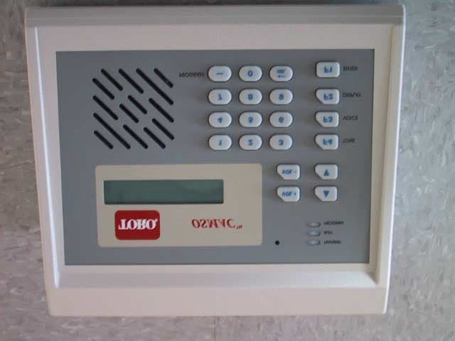
MNT-PC-UC-1
Mar 29, 2001OSMAC Base
Equipment Class
TNB - Licensed Non-Broadcast Station Transmitter
MNT-PC-US-1
Mar 25, 2001OSMAC Base
Equipment Class
TNB - Licensed Non-Broadcast Station Transmitter
MNT-PTX-150
May 04, 2000Digital Paging Transmitter
Equipment Class
TNB - Licensed Non-Broadcast Station Transmitter