MNT-PC-VB
Vytek Inc
Click to zoom
Application Details
- Equipment Class
- TNB - Licensed Non-Broadcast Station Transmitter
- Date of Grant
- Apr 25, 2000
- Application Purpose
- Original Equipment
- Date of Application
- Feb 13, 2000
- Frequency Range
- 150.00000000 - 174.00000000
- Company
- Vytek Inc
- Country
- United States
Documents & Files
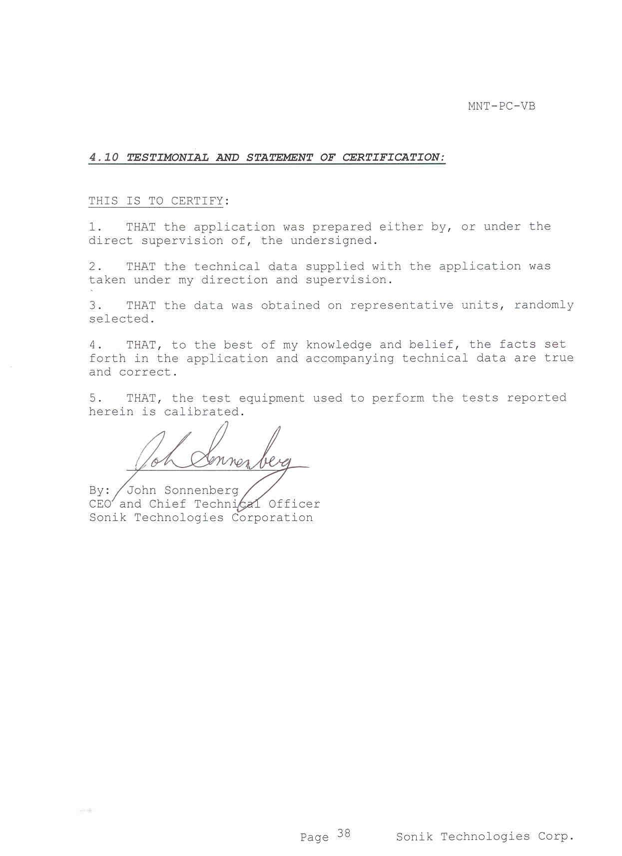
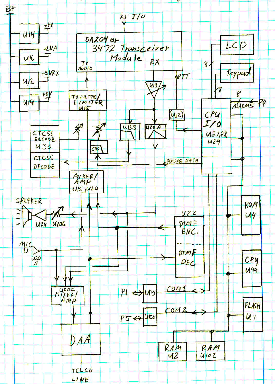
Document Text
Text extracted from the exhibit documents filed with the FCC. Open a document above to read the original.
Users Manual
Page Center User ManualMNT-PC-VB Page 1 PAGE CENTER On-Site Communications System User Manual Firmware Version 307D31 Sonik Technologies Corp. 310 Via Vera Cruz San Marcos, CA 92069 PH: 760-752-1011 Fax: 760-752-1411 Email: [email protected] Page Center User ManualMNT-PC-VB Page 2 Table Of Contents 1Installation ..................................................................................................................................................... 4 1.1Environment........................................................................................................................................... 4 1.2Licensing................................................................................................................................................ 4 1.3Radio Communication Interference ....................................................................................................... 4 1.4Locating the PAGE CENTER................................................................................................................ 4 1.5Unit Setup .............................................................................................................................................. 4 2Keypad Operation .......................................................................................................................................... 5 2.1Overview................................................................................................................................................ 5 2.2Keypad ................................................................................................................................................... 6 2.3Display ................................................................................................................................................... 6 2.4Sending a page ....................................................................................................................................... 7 2.5Group Page ............................................................................................................................................ 7 2.6Tone Paging ........................................................................................................................................... 8 2.72-way voice communications................................................................................................................. 8 3Two-way Radio and Telephone Operation .................................................................................................... 9 3.1Sending Pages from the Two-Way Radio .............................................................................................. 9 3.2Placing Telephone Calls from the Two-Way Radio ............................................................................ 10 3.3Receiving Telephone Calls at the Two-Way radio ..............................................................................11 3.4Sending Pages using the Telephone Interface ...................................................................................... 12 4Unit Setup .................................................................................................................................................... 13 4.1Configuration Mode............................................................................................................................. 14 5Program Mode ............................................................................................................................................. 17 5.1Assign Pager ........................................................................................................................................ 17 5.2Assigning a Group ............................................................................................................................... 18 5.3Sending Test Pages .............................................................................................................................. 19 5.4Alarm Pages ......................................................................................................................................... 19 5.5Phone Autodial Memories ................................................................................................................... 20 6Diagnostics................................................................................................................................................... 22 6.1Built-in Diagnostics ............................................................................................................................. 22 6.2Remote Diagnostics ............................................................................................................................. 22 7Serial Port Protocols .................................................................................................................................... 23 7.1TAP ...................................................................................................................................................... 23 7.2TAP Protocol Issues............................................................................................................................. 25 7.3Sending Multiple-Line Pages ............................................................................................................... 26 7.4Computing the Checksum .................................................................................................................... 26 7.5COMP1 ................................................................................................................................................ 26 Page Center User ManualMNT-PC-VB Page 3 7.6COMP2 ................................................................................................................................................ 27 7.7ASCII control characters..…
Text truncated - open the document above for the full version.
Cover Letter(s)
MNT-PC-VB Sonik Technologies Corporation 310 Via Vera Cruz #111, San Marcos, CA, 92068 Phone: 760-752-1011 Fax:760-752-1411 Email:[email protected] Sonik Technologies Corporation 310 Via Vera Cruz #111 San Marcos, CA 92069 Ph: 760-752-1011 Fax:760-752-1411 DATE: January 10, 2000 Federal Communications Commission EQUIPMENT APPROVAL SERVICES P.O. Box 358315 Pittsburgh, PA 15251-5315 Attention: Authorization & Evaluation Division Applicant: SONIK TECHNOLOGIES CORPORATION Equipment: FCC ID: MNT-PC-VB FCC Rules: 22, 90 Gentlemen: Enclosed please find Application Form 731, Test Data Report and all pertinent documentation, the whole for type acceptance of the referenced equipment as shown. The product we are applying for is an FM transceiver intended for one-way radio paging and two-way voice communication. The trade name we will use on it is “Zetron Page Center”. We trust all is in order. Should you need any further information, kindly contact me. Sincerely yours, John Sonnenberg Sonik Technologies Corporation CEO MNT-PC-VB Sonik Technologies Corporation 310 Via Vera Cruz #111, San Marcos, CA, 92068 Phone: 760-752-1011 Fax:760-752-1411 Email:[email protected] LIST OF EXHIBITS APPLICANT: SONIK TECHNOLOGIES CORPORATION EQUIPMENT: MNT-PC-VB EXHIBITS: Exhibit ALocation and format of FCC label. Exhibit BRegulatory Compliance report, which contains: Compliance Statements Declaration of Conformance Technical Report Exhibit CUser Manual Exhibit DTechnical manual which incorporates: Alignment Theory of Operation Circuit description List of active components Exhibit EBlock Diagram Exhibit FSchematic Diagram of main board Exhibit GTechnical manual of transceiver module Exhibit HPhotographs Exhibit IEmissions test data and report from EESI lab. MNT-PC-VB Sonik Technologies Corporation 310 Via Vera Cruz #111, San Marcos, CA, 92068 Phone: 760-752-1011 Fax:760-752-1411 Email:[email protected] Exhibit A Exhibit B Exhibit C Exhibit D Exhibit E Exhibit F Exhibit G Exhibit H Exhibit I
Cover Letter(s)
From: Sonik Technologies Corporation By:John Sonnenberg Re:FCC application MNT-PC-VB FCC correspondence number 12857 Application EA96775 Date:April 12, 2000 To:FCC Application Processing Branch Attn:George Tannahill Mr. Tannahil, This letter is in response to your Correspondence of March 17 th , reference number 12857. 1. Noted that the 11K0F1D will not be listed. 2. Photos of the unit have been uploaded again, on April 12, 2000. 3. The frequency shown in section 4.1 for low-power mode was incorrectly reported in the test data. The table should read as follows: 1. MEASUREMENT RESULTS Nominal Frequency, MHzRF Power Output, Watts 1502.1 1621.9 1741.8 4. You are correct, that the voice occupied bandwidth plots are mislabeled. The plot in 4.3.2 should be labeled as Narrow-band mode, and the plot in 4.3.3 should be labeled as wide-band mode. 5. We have studied the occupied bandwidth masks and now understand why we drew it wrong on the plots. My apology. 6. Noted that transient limits are drawn wrong between t2 and t3. I hope this answers all of your questions concerning this filing. Please let me know if you wish us to submit any other information. Regards, John Sonnenberg CEO, Sonik Technologies Corporation
External Photos
MNT-PC-VBSonik Technologies Corporation Photos of Product MNT-PC-VB: Front View MNT-PC-VBSonik Technologies Corporation Top View MNT-PC-VBSonik Technologies Corporation Inside, showing main board with shields MNT-PC-VBSonik Technologies Corporation Inside Top Cover MNT-PC-VBSonik Technologies Corporation Bottom Side of Main Board MNT-PC-VBSonik Technologies Corporation Rear view of Main Board MNT-PC-VBSonik Technologies Corporation Top View of Main Board MNT-PC-VBSonik Technologies Corporation Rear View of unit MNT-PC-VBSonik Technologies Corporation Bottom of RF board MNT-PC-VBSonik Technologies Corporation Top-side view of RF board
ID Label/Location Info
MNT-PC-VB 1. Exhibit A FCC Identifier Label The label shown below shall be attached to the bottom of the transceiver in the location shown. They type size is eight-point. FCC ID label Location of label is centered, on bottom of unit.
Internal Photos
TO: George Tannahill [email protected] FCC Application Processing Branch From: John Sonnenberg, Sonik Technologies Corporation Re: FCC ID: MNT-PC-VB Applicant: Sonik Technologies Corporation Correspondence Reference Number: 13572 731 Confirmation Number: EA96775 Date of Original E-Mail: 04/20/2000 Per your request here is the photograph you would like to see of the component side of the main board, with the shields removed. If you have any further questions, please feel free to contact me. Regards, John Sonnenberg CEO Sonik Technologies Corporation
Operational Description
MNT-PC- VB PageCenter Technical Manual December 1999 Sonik Technologies Corporation MNT-PC- VB 1 Technical Description 1.1 Overview The PAGE CENTER is a desk top system that provides paging and wireless two-way communications. With an Intel 32 bit processor at its core, and 4 megabytes of FLASH memory, the PAGE CENTER can handle the wireless communications needs of the small office or a large plant. It is designed to be form and function compatible with Mororola’s discontinued “PeopleFinder” paging system. Internally, it has two distinct circuits, a “Main Board” that controls the unit, and an “RF Board” that contains the transmitting and receiving circuits. The RF Board is enclosed within a metal shield on the Main Board. PAGE CENTER features: Stand-alone operation with built-in keypad and LCD display. Build-in RS-232 serial port for advanced paging applications. Built-in telephone interface for remote access. Internal two-way radio for monitoring the channel and two-way voice communication. POCSAG paging encoder at 512, 1200, and 2400 baud 1000 pager database Group paging 8 external alarm inputs for automatic generation of pre-programmed pages. Pages may be initiated from DTMF equipped two-way radios. Built-in speaker and microphone, with provisions for external connections. Operation on either wide or narrow band channels. Internal time-out-timer Automatic disconnect of telco on no-activity. Busy channel lock-out to avoid transmitting on an active channel. The PAGE CENTER operates in one of two basic modes. They are the Page Mode and the Program Mode. The Page Mode is used to send digital pages to a selected pager or group of pagers. It may also be used to communicate with a two-way radio. For the PAGE CENTER to send pages to a pager, it must first be programmed with the pager's CAP code. This is done, one time, using the Program Mode. The Program Mode is used to set up the individual pager's information, group information, automatic paging information, and some system-level features. Although the operator may send pages using the built-in keypad, pages may also be generated in a variety of other ways. Pages may be initiated through the RS-232 serial port on the rear of the unit. Another way is to use the built-in telephone interface. When connected to a telephone line, pages may be entered using a touch-tone phone by dialing MNT-PC- VB into the unit. The PAGE CENTER may also be configured to automatically generate a page, based upon an electrical input to special input pins on the rear of the unit. A busy- channel detect circuit disables transmitting if the channel is busy. The PAGE CENTER has an internal database, which stores the CAP code for every pager in your system. The CAP code is the special 7 digit code that identifies an individual pager or paging receiver device. To make paging simpler, you need only configure the CAP codes once by assigning an easy-to-remember number or name to it. For instance, you may have 3 pagers with the following CAP codes: 1924589, 0029111, 0935199. You can program them into the database as pager names 1, 2, and 3 as follows: Pager CAP Code Pager Name 19245891 00291112 09351993 Internal to the PageCenter, there is a motherboard (part number 5A296) and a radio transceiver module (part number 5A204). The radio transceiver module is enclosed in a metal shield on the motherboard. The service manual for the 5A204 transceiver is available separate from this Technical Manual. 2 Types of Emissions The PageCenter uses FM modulation for all communications. It has four modulation modes, wide/narrow bandwidth and voice/data modes. They are: Mode Designator Voice from mic or telco, 5kHz deviation limiter 16K0F3E Voice from mic or telco, 2.5kHz deviation limiter11K0F3E POCSAG paging data, +/- 4.5kHz deviation16K0F1D POCSAG paging data, +/- 2.25kHz deviation11K0F1D The mode of operation is automatically switched by the PageCenter, depending upon how the unit is being used. It switches to voice mode when audio is being transmitted, and to data mode when POCSAG data is being transmitted. The PageCenter’s transmitter is configured at the factory, or at a service shop, to be either a wide-band or a narrow-band transmitter. This is configured via software as well as the frequency of operation and any sub-audible signaling. Wide mode is provided for operation on older 25kHz spaced systems, and narrow mode is provided for operation on 12.5kHz spaced channels. 3 Function of Active Devices Active devices on main board Reference DesignatorFunction HY1Telephone interface hybrid OSC148MHz clock for the CPU. Q1Serial ID ROM MNT-PC- VB Q9Mic AGC adjustment U10, U105RS232 transceiver for serial I/O U101Inverter for memory timing U104CMOS audio switch to connect audio paths for the various modes U104DCMOS switch that changes the gain of the post-limiter mixer. It changes gain by 50% when the radoi is on a narrow-band channel. U105Inverter for AT type keyboard interface. U106Digital pot to adjust volume U107Audio switch to connect various audio paths U108AMixes DTMF encode audio with speech synthesizer. U108BBuffer/mixer for local speaker audio U11FLASH memory for data and program storage U13AComparator for channel busy detect circuit. U14,U7, U19Voltage regulators U15APost-limiter mixer. Combines pre-emphaisezed audio with digital paging and sub-audible signaling. Reduces input signals to 1.7V p-p. U15BSplatter filter. 3kHz low-pass filter to meet emission mask and filter requirements. U15CAudio pre-emphasis and limiter. Power rails are used to limit output signal. U15DMixer. Combines mic, DTMF, telephone, and speech synthsizer audio. U2, U102RAM memory U20AMic amp U20B300Hz high pass filter, unity gain U20CBuffer/mixer for audio going to telephone interface. U20DNoise-amp ofr channel busy detector. U22DTMF encoder and decoder U23Voice synthesizer D/A converter. U241 watt audio amplifier U25CMixer/buffer for audio to telephone interface. U25DData recovery circuit to receive DPL s…
Text truncated - open the document above for the full version.
Schematics
A A B B C C D D E E 44 33 22 11 Flash SRAM 128KX16 BOOT PROM Digital I/O #1 EEPROM, POR, WD KeyPad Digital I/O #2Digital I/O #3 CPU Test Port INPUTS Contrast Hard Jumper TP17 - TP34 5A296 PageCenter Central Procesor C 14Tuesday, November 02, 1999 Sonik Technologies Corp. CONFIDENTIAL D17 Title SizeDocument NumberRev Date:Sheet of BLE CPU_A22 CPU_A1 CPU_A15 CPU_A13 CPU_A3 CPU_A16 CPU_A7 CPU_A5 CPU_A8 CPU_A12 CPU_A21 CPU_A10 CPU_A6 CPU_A8 CPU_A13 CPU_A14 CPU_A6 CPU_A17 CPU_A2 CPU_A11 CPU_A19 CPU_A25 CPU_A20 CPU_A11 CPU_A4 CPU_A9 CPU_A18 CPU_A10 CPU_A5 CPU_A9 CPU_A1 CPU_A3 CPU_A24 CPU_A4 CPU_A23 CPU_A12 CPU_A14 CPU_A15 CPU_A2 CPU_A7 CPU_A17 CPU_A9 CPU_A13 CPU_A1 CPU_A4 CPU_A11 CPU_A6 CPU_A2 CPU_A3 CPU_A7 CPU_A10 CPU_A19 CPU_A8 CPU_A12 CPU_A5 CPU_A16 CPU_A14 CPU_A18 CPU_A15 CPU_A1 CPU_A2 CPU_A3 CPU_A4 CPU_A5 CPU_A6 CPU_A7 CPU_A8 CPU_A9 CPU_A10 CPU_A11 CPU_A12 CPU_A13 CPU_A14 CPU_A15 CPU_A16 CPU_A1 CPU_A2 EE_CLK EE_SI EE_WP PT1_8 PT1_9 PT1_10 PT1_11 PT1_13 PT1_17 PT1_14 PT2_0 PT2_1 PT2_2 PT1_18 PT1_19 PT2_3 PT2_5 PT2_6 PT2_7 PT1_16 PT1_22 PT2_8 PT2_11 PT2_12 PT1_21 PT1_20 PT1_15 CPU_D1 CPU_D2 CPU_D3 CPU_D4 CPU_D5 CPU_D6 CPU_D7 PT3_0 PT3_2 PT3_3 PT3_4 PT3_5 CPU_A16 BS8 PT3_8 PT3_9 PT3_10 PT3_11 PT3_12 PT3_13 PT3_6 PT3_7 PT3_14 PT3_15 CPU_D6 CPU_D7 CPU_D7 CPU_D8 CPU_D2 CPU_D3 CPU_D15 CPU_D4 CPU_D1 CPU_D6 CPU_D5CPU_D4 CPU_D14 CPU_D2 CPU_D5 CPU_D1 CPU_D5 CPU_D6 CPU_D6 CPU_D4 CPU_D11 CPU_D5 CPU_D1 CPU_D2 CPU_D12 CPU_D6 CPU_D7 CPU_D8 CPU_D12 CPU_D4 CPU_D2 CPU_D0 CPU_D4 CPU_D3 CPU_D14 CPU_D13 CPU_D13 CPU_D0 CPU_D3 CPU_D3 CPU_D1 CPU_D0 CPU_D7 CPU_D7 CPU_D0 CPU_D0 CPU_D3 CPU_D9 CPU_D1 CPU_D10 CPU_D9 CPU_D15 CPU_D5 CPU_D11 CPU_D10 CPU_D2 CPU_A20 CPU_A21 KBCLK CPU_A17 CPU_D0 CPU_D1 CPU_D2 CPU_D3 CPU_D4 CPU_D5 CPU_D6 CPU_D7 CPU_A1 CPU_A2 CPU_A3 CPU_A4 CPU_A5 CPU_A6 CPU_A7 CPU_A8 CPU_A9 CPU_A10 CPU_A11 CPU_A12 CPU_A13 CPU_A14 CPU_A15 CPU_A16 CPU_A17 CPU_D8 CPU_D9 CPU_D10 CPU_D11 CPU_D12 CPU_D13 CPU_D14 CPU_D15 CPU_D0 CPU_A17 BLE M/IO CPU_RD CPU_WR CPU_R/W READY BHE D/C ADS RESET LBA BS8 DR_OE PT3_1 PT1_23 PT1_12 PT2_10 PT2_4 PT2_9 KB_ROW1 KB_ROW2 KB_ROW3 PGM_LED PT3_16 PT3_17 PT3_18 PT3_19 PT3_20 PT3_21 PT3_22 PT3_23 PT2_16 PT2_17 PT2_18 PT2_19 PT2_20 PT2_21 PT2_22 PT2_23 PT2_13 PT2_14 PT2_15 KBDATA CPU_D[0..15] READY BHE BLE CPU_WR CPU_RD CPU_R/W D/C M/IO ADS LBA BOOT_CS 232_DCD 232_DSR 232_RXD 232_CTS 232_TXD 232_RTS 232_DTR SRAM_CS FLASH_CS BOOT_CS RESET CPU_A[1..25] SRAM_CS CPU_RD IO_CS1 IO_CS1 CPU_RD CPU_WR PLL_LE PLL_CLK PLL_D PA_ON IO_CS2 CPU_RD CPU_WR IO_CS2 RX_ON RX_MUTE MIC_MUTE TEL_MUTE TX_BEEP OFF_HOOK TelVoiceEn DIG_OUT5 DA_CS IO_CS3 IO_CS3 DB0 DB1 DB2 DB3 DB4 DB5 DB6 DB7 DTMF_CS MX_CE DAC_CS LCD_R/W LCD_E LCD_RS DTMF_RX DTMF_TEL DTMF_RD DTMF_RS DTMF_DS MX_PTL MX_RX AUX_IN1 AUX_IN2 AUX_IN3 AUX_IN5 AUX_IN4 AUX_IN6 AUX_IN7 AUX_IN8 DIG_OUT2 DIG_OUT1 DIG_OUT3 DIG_OUT4 POCSAG_ON DCS_ON CPU_RD RESET CPU_WR FLASH_WP FLASH_WP BLE LCD_ELCD_R/W LCD_RS DB0DB1 DB2DB3 DB4DB5 DB6DB7 KBDO CPU_WR SRAM_CS CPU_RD CPU_WR SRAM_CS FLASH_CS BOOT_CS IO_CS1 IO_CS2 IO_CS3 232_RXD 232_TXD 232B_DCD 232B_DSR 232B_RXD 232B_CTS 232B_TXD 232B_RTS 232B_DTR CPU_RESET CPU_RESET CPU_RESET BLE BHE LOCAL_SYNTH LINE2RADIO DTMF_EST TelcoRing CD MX_DEC DTMF_DEC FLASH_CS W/NB DCS_DATA LFDATA DCS_ENC PL-DCS TEL_VOX MIC_VOX TX_LED BUSY_LED VOL_DN VOL_UP DIG_OUT3 DIG_OUT1 DIG_OUT2 MIC2TEL TELCO_EN1 TELCO_MUTE LINE_MUTE KBDO KBCO KBCO BUSY_LED +5V +5V +5V +5V +5V VCC VCC VCC VCC +5V +5V VCC +5V +5V +5V +5V +5V +5V +5V +5V VCC C4 .1uF C3 .1uF C2 .1uF R1 10k C5 .1uF C6 .1uF Q1 DS2401 23 1 4 R5 4.7k R2 10k C1 .1uF C9 .1uF C10 .1uF S1 NP - RESET 12 U4 AT27C010/L-JC A0 12 A1 11 A2 10 A3 9 A4 8 A5 7 A6 6 A7 5 A8 27 A9 26 A10 23 A11 25 A12 4 A13 28 A14 29 CE 22 OE 24 VPP 1 O0 13 O1 14 O2 15 O3 17 O4 18 O5 19 O7 21 O6 20 VCC 32 GND 16 A15 3 A16 2 NC(A17) 30 PGM(A18) 31 U11 28F160S A0 37 A1 51 A2 50 A3 49 A4 48 A5 47 A6 46 A7 45 A8 43 A9 52 A10 53 A11 54 A12 2 A13 3 A14 4 A15 5 A16 13 A17 12 OE 21 D0 38 D1 40 D2 33 D3 31 D4 27 D5 25 D6 16 D7 18 D8 39 D9 41 D10 32 D11 30 D12 26 D13 24 D14 17 D15 19 GND 44 WE 22 BTYE 36 CE0 1 R/P 55 A18 11 CE1 7 GND 29 NC 6 NC 34 Vcc 42 NC 35 A19 10 A20 9 A21 8 WP 23 STS 20 GND 15 Vcc 28 Vcc 14 Vpp 56 U99 80386EX D0 5 D1 6 D2 7 D3 8 D4 10 D5 11 D6 12 D7 13 D8 14 D9 16 D10 18 D11 19 D12 20 D13 21 D14 22 D15 23 TDO 24 TDI 25 TMS 26 CS6/REFRESH 2 CS5/DACK0 128 CS4/P2.4 126 CS3/P2.3 125 CS2/P2.2 124 CS1/P2.1 123 CS0/P2.0 122 UCS 1 RESET 110 SMI 73 INT0/P3.2 80 INT1/P3.3 82 PEREQ 89 BUSY/TMRGATE2 92 ERROR/TMROUT2 91 INT2/P3.4 84 NMI 90 TMROUT0/P3.0 74 A2 43 A3 44 A4 45 A5 48 A6 49 A7 50 A8 51 A9 52 A10 53 A11 54 A12 55 A13 56 A14 57 A15 58 A16/CAS0 59 A17/CAS1 61 A18/CAS2 62 A19 63 A20 65 A21 66 A22 67 A23 68 A24 70 A25 72 W/-R 30 D/-C 29 M/-IO 27 ADS 40 LBA 4 FLT 99 CLKOUT 103 WDTOT 114 P1.5/LOCK 107 P1.7/HOLDA 111 VCC 9 VCC 15 VCC 28 VCC 38 VCC 47 VCC 60 VCC 71 VCC 81 VCC 88 VCC 109 VCC 121 VCC 127 GND 3 GND 17 GND 31 GND 36 GND 46 GND 64 GND 69 GND 83 GND 97 GND 100 GND 116 GND 130 A1 42 RD 34 WR 35 BLE 37 BHE 39 READY 32 BS8 33 INT4/TMRCLK0 93 INT5/TMRGATE0 94 INT6/TMRCLK1 95 INT7/TMRGATE1 96 TMROUT1/P3.1 75 TCK 76 DTR1 77 RI1 78 RTS1 79 TXD1 112 CTS1 113 DTR0 104 RI0 106 RTS0 102 TXD0 131 CTS0 132 RXD0 129 RXD1 118 DCD1 117 DSR0 105 DCD0 101 INT3/P3.5 85 P3.6/PWRDOWN 86 P3.7/COMCLOCKPWRDOWN 87 DSR1 98 CLK2 115 TRST 119 SMIACTIVE 120 NextAddr 41 P1.6 108 TP18TP17 TP19 OSC1 48.000MHz Vt 1 GND 7 Vcc 14 Out 8 U29 82C55_PLC44 D0 38 D1 37 D2 36 D3 35 D4 33 D5 32 D6 31 D7 30 RD 6 WR 40 A0 10 A1 9 RESET 39 CS 7 PA0 5 PA1 4 PA2 3 PA3 2 PA4 44 PA5 43 PA6 42 PA7 41 PB0 20 PB1 21 PB2 22 PB3 24 PB4 25 PB5 26 PB6 27 PB7 28 PC0 16 PC1 17 PC2 18 PC3 19 PC4 15 PC5 14 PC6 13 PC7 11 NC 34 Vcc 29 Gnd 8 NC 23 NC 12 NC 1 U28 82C55_PLC44 D0 38 D1 37 D2 36 D3 35 D4 33 D5 32 D6 31 D7 30 RD 6 WR 40 A0 10 A1 9 RESET 39 CS 7 PA0 5 PA1 4 PA2 3 PA3 2 PA4 44 PA5 43 PA6 42 PA7 41 PB0 20 PB1 21 PB2 22 PB3 24 PB4 25 PB5 26 PB6 27 PB7 28 PC0 16 PC1 17 PC2 18 PC3 19 PC4 15 PC5 14 PC6 13 PC7 11 NC 34 Vcc 29 Gnd 8 NC 23 NC 12 NC 1 JP1 LCD 12 34 56 78 …
Text truncated - open the document above for the full version.
Schematics
1 1 2 2 3 3 4 4 5 5 6 6 7 7 8 8 AA BB CC DD B C6 C7 C8 C66 C10 C11 C13 C14 33 56 56 22 47 15 18 10 150-174 Power Adjust 218-230 15 24 24 L15639 39 20 L4,5,7,8REDGreen 18 C19157 L6-3B 27 R31.5k3.3K R46.8K4.7k R51K2.2K C16108 C30,21.751.0 C181012 C2033220 C19715 L125627 C4910NP L143322 C531018 C598NP L168Jumper L1810T3T L1910T8T C562210 C674030 C654020 240-260 D1D2 18 33 27 1010 39 12 12 15 33 RED 18 -2B(Unsh.)-2B(Unsh.) 6.8K 1K 1.5k 6 .75 5 18 18 22 NP 22 22 8 Jumper 3T 6T 22 30 10 Notes: 1. Resistors in ohms, capacitors in pF, inductors in nH unlss noted otherwise. 2. Values shown are for A band (136-150MHz). Other bands per chart. 3. When L16 must be jumpered, jumper to be 20AWG, directly to C60 pad. 4. -NB ( 12.5kHz spacing narrow band) option values shown in { }. 5. Levels shown are measured with high-Z meter assuming 50 ohm load. RX levels are with -40dBm RF input. 6. Y1 and Y2 are matched pairs and must be maintained as sets. {21M7B}{21M7B} [>350mV p-p at 21.4MHz w/-40dBm input] [>-23dBm] [+34dBm][+23dBm] [+8dBm] [+13dBm] [+0dBm] { 4 } { 12 } { 330 } {SFG455G}{SFG455G} D3 SONIK TECHNOLOGIES CORPORATION C 12Thursday, November 19, 1998 5A204D C:\PCBS\204D\SCH\5A204D.DSN SizeDocument NumberRev Date:Sheet of +5V +5VRX +5VRX +5VRX +7.5VTX B+ +7.5VTX +5VRX +5V +7.5VTX B+ +7V B+ B+ U1 MC3371 CRYS.OSC. 1 MIX.IN 16 CRYS.OSC. 2 MIS.OUT 3 VCC 4 LIM.IN 5 DEC. 6 DEC. 7 QUADCL. 8 GND 15 MUTE 14 MET.DRV. 13 SQU.IN 12 FILT.OUT 11 FILT.IN 10 REC.AUD. 9 C1 220 C2 220 C3 220 C4 220 C5 10uF 16V C6 39 C7 56 C8 75 C9 .01uF R1 150 L1 56 L2 10T L3 10T C10 68 C11 15 L4 YEL 1 2 C12 1.5 L5 YEL 1 2 C13 22 C14 15 R2 2.2K R3 1.5K R4 6.8K C15 1000 R5 1K L6 ORG C16 22 R6 270 C17 .01uF Q1 571 C18 15 L7 YEL 1 2 L8 YEL 1 2 C19 10 R7 39K R8 10K C20 220 C21 1 C22 .022uF C23 47pF C24 1000 Q2 BF990A C25 1000 R9 390 C26 9pF Y1 21M15B 13 2 C27 3 Y2 21M15B 13 2 R10 1k Q3 H10 C28 .022uF TP1 R11 470K R12 4.7K C29 1000 C30 1 TP2 C31 NP R13 100 Y3 20.945 C32 68 R14 39K C3347 C34 .1uF C35.1uF C36.01uF R15 1K C37 2200 C38 2200 C39 2200 C40 2200 C41 2200 C42 2200 ANT1 ANTENNA L10 680 C43 2200 D2 9401 D3 9401 C44 2200 C46.1uF C47 10uF 16V + R16 33K L12 56 L14 33nH C48 1000 R17 390 Q4 MMBR941 C49 15 C50 .01uF C51 1000 Q5 8372 C53 18 L16 8.2nH C54 1000 C55 .01uF L18 10T R18 220 R19 220 Q6 RF260 L19 10T C56 22 R20 22 R21 22 R22 3k C58 20 C59 8 C60 30 C61 10uF 16V C62 2200 C64 2200 C65 30 C66 10 C67 30 C68 2200 J1 I/O 1 2 3 4 5 6 7 8 9 10 11 12 13 14 R74 27 C122 1000 R75 220 Z1 SFG455D 123 Z2 SFG455D 123 R100 NP U20 LP2951 OUT 1 SENSE 2 SO 3 GND 4 ER 5 NC 6 NC 7 IN 8 R79 47k R80 10k C128 NP Q16 7002 R81 100k D1 BAV99 1 3 L13 NP FB1 0S0 1 2 Q18 BSP31 23 1 4 R104 2.2 R101 100 R102 22 R105 1k Q17 7002 R103 1k D9 BAV99 13 C63 1uF A C57 1uF A L111055Z 13 6 7 L9 1uH 1 267 RX_LO TXOUT RX_OUT SYN_CLK SYN_DATA SYN_EN TX_IN RX_OUT RSSI RSSI TXOUT TX_A A A B B C C D D E E 44 33 22 11 RXVCO TXVCO Modulation Balance B C119 C133 C118 C114 C85 C132 C116 C77 10 68 12 8 22 27 10 12 150-174218-230 NP 15 10 C781812 18 15 L25BRNRED 8 8 C801510 C811812 10 L26REDORG 812 C1301215 C892268 C881218 L22,L23REDGRN C110 C1171.5 C1111012 0V=TX 5V=RX DD2 3 15 9 8 9 8 18 15 9 7 8 BRN BRN 6 4 22 3 ORG .5 10 L2122022033 5A204 D3 VHF Transceiver PCA C 22Thursday, November 19, 1998 Sonik Technologies Corp. Title SizeDocument NumberRev Date:Sheet of TX_IN SYN_EN SYN_CLK SYN_DATA RX_LO RX/TX RX/TX TX_A +5V B+ +5VCO +5V +7V +7V +5VCO +5VCO +5VCO RT1 100 B=2930 t R25 10k D4 2103 C71 15 R30 7.5k R31 680 R32 680 R33 10 C73 .1uF R34 33K R35 10 C74 .1uF C75 3900 NPO C76 1000 NPO R36 27K R37 27K C77 12 C78 18 R38 680 R39 27K C79 1000 C80 15 C81 18 R40 1K R41 22K Q7 571 R42 27K R43 22K C82 NP R44 10K R45 27K R46 680 C83 1000 C84 NP L20 220 C85 22pF C86 1000 C87 2200 R47 3.9K R48 120 R49 3.9K L21 220 L22 GRN C88 18 R50 2.2K C89 27 C90 1 L23 GRN R51 2.2K R52 10 R53 10k C93 680pF R54 10K R55 10K C94 680P Q8 H10 C95 330 C96 150 R56 5.1K R57 10K R58 47k C99 1000 C100 N.P. R59 1M C101 100pF Y4 14.4 R60 5.6k C102 2200 R61 10 C103 2.2 10V + R63 10 R64 100 R65 68 R66 NP C104 10 C105 1000 C106 68pF C107 1000 C108 2200 C109 2200 C110 12 C111 10 Q9 941 Q10 941 Q11 941 C112 .01uF C113 2.2uF 10V + C114 10 Q12 571 Q13 3904 C115 12 R67 22K R68 22K Q14 3904 Q15 3904 C116 10 L25 RED C117 1 C118 12 L26 ORG C119 12 R69 10K D8 2103 R71 220k R72 10k U2 LP2982 1 1 2 2 3 3 4 4 5 5 U3 145190 REF OUT 1 LD 2 *R 3 *V 4 VPD 5 PD OUT 6 GND 7 RX 8 TEST 1 9 FIN 10 REF IN 20 DATA 19 CLK 18 ENB 17 OUTPUT A 16 OUTPUT B 15 VDD 14 TEST 2 13 VCC 12 FIN 11 TP3 TestPoint C91 10pF D5 2109 L29 3.3uH R77 10k C72 .1uF R62 NP R73 NP D7 MMBV609 1 3 D6 MMBV609 1 3 C130 18 R27 3.3k RT2 2252 b=3890 t C150 1uF A C120 1000 C131 4 R82 100k C98 .47uF A C97 .047uF A C133 27 R83 10k 1 2 C132 27 CX134 .01uF
Test Report
MNT-PC-VB Page Sonik Technologies Corp. 1 Regulatory Compliance Report EQUIPMENT IDENTIFICATION FCC ID: MNT-PC-VB Applicable FCC Parts 22, 90 NAMEPLATE DRAWING ATTACHED, EXHIBIT A. LOCATION AS PER LABEL DRAWING(S) DATE OF REPORT February 7, 2000 Supervised By: John Sonnenberg CEO/Chief Technical Officer Sonik Technologies Corporation MNT-PC-VB Page Sonik Technologies Corp. 2 Table of Contents 1. STATEMENTS.............................................................. 3 1.1INFORMATION TO USER(CFR 15.21)....................................................................................................... 3 1.2SPECIAL ACCESSORIES (CFR 15.27(a)) ................................................................................................... 3 1.3Spectrum Efficiency Certification(CFR 2.203(j)(i)) ....................................................................................... 3 1.4Programmability (CFR 90.203(g)).................................................................................................................. 3 2. DECLARATION OF CONFORMITY (CFR 2.1071).................................. 4 3. STANDARD TEST CONDITIONS AND ENGINEERING PRACTICES...................... 7 4. TEST RESULTS............................................................ 8 4.1RF Power Output ............................................................................................................................................ 8 4.2VOICE MODULATION CHARACTERISTICS – ........................................................................................ 9 4.2.1 FREQUENCY RESPONSE OF LOW_PASS FILTER AFTER LIMITER IN MODULATING CIRCUIT:10 4.2.2 MODULATION LIMITING ..................................................... 11 4.2.3 FREQUENCY RESPONSE OF MICROPHONE AUDIO MODULATING CIRCUIT ............... 13 4.2.4 FREQUENCY RESPONSE OF TELEPHONE INTERFACE AUDIO MODULATING CIRCUIT ...... 14 4.3OCCUPIED BANDWIDTH......................................................................................................................... 15 4.3.1 Total Channel Power ..................................................... 17 4.3.2 Occupied bandwidth, Wide-band mode (25kHz) .............................. 17 4.3.3 Occupied Bandwidth, Narrow-band Mode (12.5kHz) .......................... 18 4.3.4 Occupied Channel Bandwidth in POCSAG encode mode ........................ 19 4.4TRANSMITTER CONDUCTED SPURIOUS EMISSIONS....................................................................... 21 4.5FIELD STRENGTH OF RADIATED SPURIOUS EMISSIONS................................................................ 23 4.6FREQU…
Text truncated - open the document above for the full version.
Contact Information
Applicant
Ronald J. Weber(Vice President)
Technical Contact
Sonik Technologies CorporationJohn R Sonnenberg
[email protected]760-752-1011
310 Via Vera Cruz #111 · San Marcos, California · United States
Non-Technical Contact
Sonik echnologies CorporationsJohn R Sonnenberg
[email protected]760-752-1011
Test Firm
TUV AmericaJames Owen
Technical Specifications
| # | Rule Parts | Frequency Range | Power Output | Emission | Tolerance |
|---|---|---|---|---|---|
| 6 | 22,90.21 | 150 MHz - 174 MHz | 2 W | 11K0F3E | 2.5 ppm |
Other Applications from Vytek Inc

MNT-PC-UC-2
Dec 21, 2005Base Station Irrigation Control Module
Equipment Class
TNB - Licensed Non-Broadcast Station Transmitter
MNT-G2BT
Jul 15, 2002Sonik G2BT Base Transmitter
Equipment Class
PCB - PCS Licensed Transmitter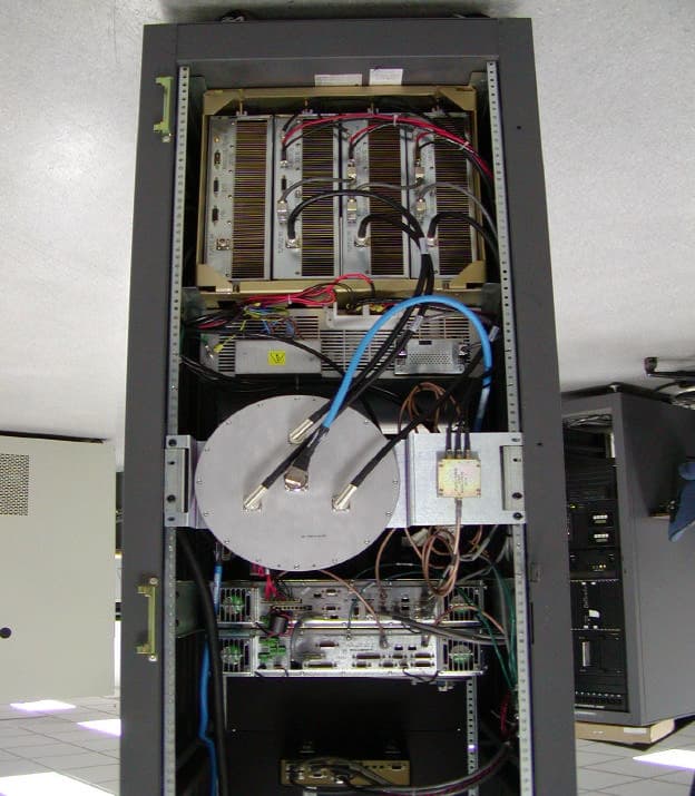
MNT0006068662
Mar 18, 2002Paging Station
Equipment Class
PCB - PCS Licensed Transmitter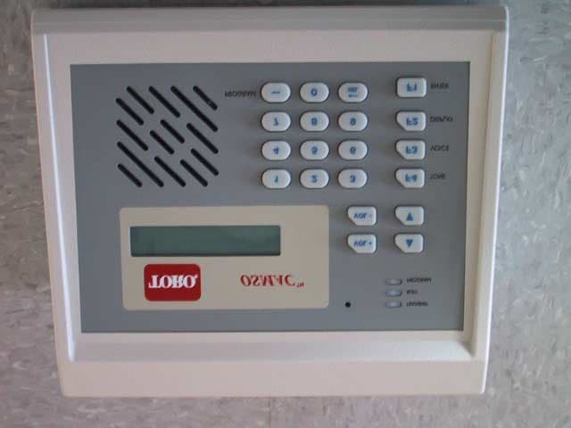
MNT-PC-UC-1
Mar 29, 2001OSMAC Base
Equipment Class
TNB - Licensed Non-Broadcast Station Transmitter
MNT-PC-US-1
Mar 25, 2001OSMAC Base
Equipment Class
TNB - Licensed Non-Broadcast Station Transmitter