MQXA720WIRELESS SENSOR INTERFACE
Adcon Telemetry Inc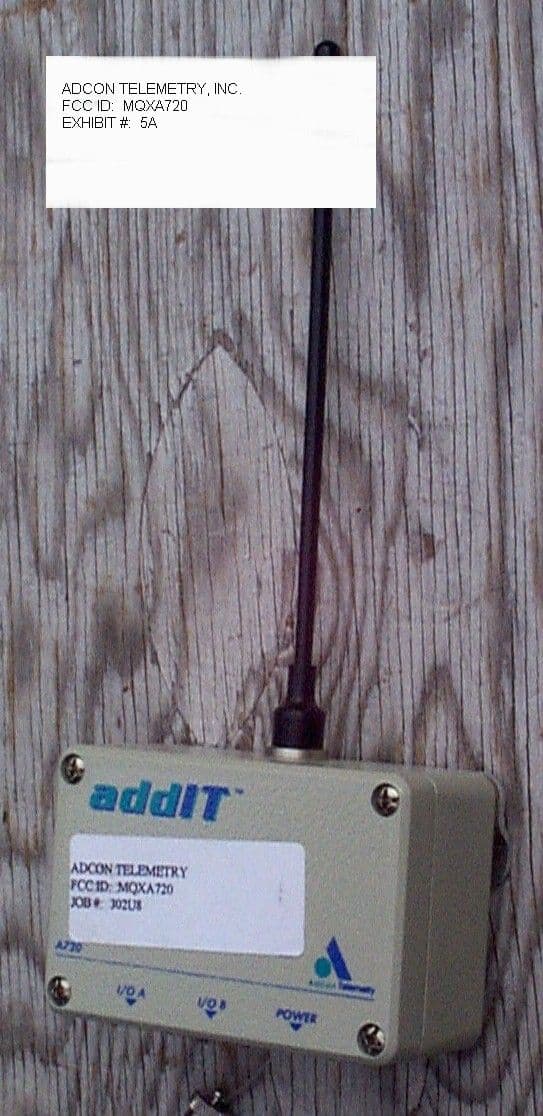
Click to zoom
Application Details
- Equipment Class
- TNB - Licensed Non-Broadcast Station Transmitter
- Date of Grant
- Jun 17, 2001
- Application Purpose
- Original Equipment
- Date of Application
- Nov 19, 1998
- Equipment Note
- WIRELESS SENSOR INTERFACE
- Frequency Range
- 432.00000000 - 470.00000000
- Company
- Adcon Telemetry Inc
- Country
- United States
Documents & Files
Document Text
Text extracted from the exhibit documents filed with the FCC. Open a document above to read the original.
Users Manual
A720 – addIT™ Technical Documentation Adcon Telemetry GmbH Inkustr. 24, A-3400 Klosterneuburg Austria Tel: +43-2243-38280 Fax: +43-2243-38280-6 http://www.adcon.at Adcon Telemetry, Inc. 1001 Yamato Road, Suite #305, Boca Raton, FL 33431 USA Tel: +1-561-989-5309 Fax: +1-561-989-5310 http://www.adcon.com Adcon Telemetry srl. Bd. Ana Ipãtescu nr. 27 ap. 11 R-71111 Bucharest Romania Tel: +40-1-312-6886 Fax: +40-1-312-6668 http://www.adcon.ro Proprietary Notice: The Adcon logo, the A730 series, addIT™, addVANTAGE and AgroExpert™ are trademarks or registered trademarks of Adcon Telemetry GmbH. All other registered names used throughout this publication are trademarks of their respective owners. This publication contains confidential information property of Adcon Telemetry GmbH. Disclosure to third parties of the information contained herein is prohibited. Neither the whole nor any part of the information contained in this publication may be reproduced in any material form except with the prior written permission of Adcon Telemetry GmbH. Release 1.0, October 1998 Copyright ©1998 by Adcon Telemetry GmbH. All rights reserved. 3 Table of Contents 1. About the A720 5 2. Hardware 6 2.1. The Radio Unit 6 2.1.1. Receiver Section 6 2.1.2. Synthesizer Section 8 2.1.3. Transmitter Section 9 2.2. The Modem Interface 9 2.3. The Microcontroller and the Power Management Sections 10 2.4. The Interface Board 11 3. Tuning Procedure 12 3.1. Programming the Boards 13 3.2. Setting-up the Default Parameters 13 3.3. Tuning 13 3.3.1. Definitions 14 3.3.2. Test Equipment Settings 15 3.3.2.1. Network Analyzer (HP 8711) 15 3.3.2.2. Service Monitor (Rohde & Schwarz CMS50) 15 3.3.3. Adjusting the Receiver Front End 16 3.3.4. Adjusting the VCOs 17 3.3.5. Checking the Receiver Parameters 17 3.3.6. Checking the Transmitter Parameters 18 3.3.7. Data Transfer Check 18 3.4. Additional Issues Related to Type Approval Testing 19 4 3.4.1. Controlling the Unit 19 3.4.2. External Power Supply 19 3.4.3. Specifications 20 3.4.4. Bill of Materials 24 3.4.5. Device Photographs 29 4. Software 34 4.1. AMOS 34 4.1.1. Initialization 35 4.1.2. 1/2 Second Interrupt 36 4.1.3. Pulse Counters Interrupt 36 4.2. Mode Check 36 4.3. A/D Task 38 4.4. The Terminal Task 39 4.4.1. Supported Commands 39 4.4.1.1. The SET Series of Commands 39 4.4.1.2. Querying the Actual Configuration Parameters 41 4.5. The Radio Interface Task 41 4.5.1. Digital Squelch 42 4.5.2. Modulation Technique Used 43 4.5.3. Generic Format of a Radio Frame 44 4.5.4. Data Frames 45 4.5.5. Frame Types 45 4.5.5.1. Request 45 4.5.5.2. Broadcast Answer 46 4.5.5.3. Set I/O Request 46 4.5.5.4. Read I/O Answer 47 4.5.5.5. Broadcast Request 47 4.5.5.6. Ping 47 4.5.5.7. Pong 47 4.5.5.8. Memory Dump Request 48 4.5.5.9. Memory Dump Answer 49 4.5.5.10. Data 49 4.5.5.11. Set ID 50 4.5.5.12. Set Slot Time and Sample Rate 50 4.5.5.13. Set Frequency 50 4.5.5.14. Set Battery Charge Levels 51 4.5.5.15. Set Pulse Counters Parameters 51 4.5.5.16. General Acknowledge 51 5 Wireless Sensor Interface A720 (addIT™) 1.About the A720 The A720 Wireless Sensor Interface (also known as addIT™ ) is a low power, short range telemetry device, capable of sampling up to 6 analog sensors and 4 digital in- puts (of which 2 counter types); in addition, it can control two relays. The frequency of operation is in the 432 to 470 MHz range, making it adaptable to most radio communication regulations in the world. The output power is under 10 mW, while the modulation is narrow band FM (12.5 or 25 kHz channel spacing). Due to its construction, as well as to the software controlling it, the power consump- tion is extremely low (average 6 mW). The unit operates from a built in NiCd 6.2 Volt rechargeable battery, which is charged either using an 600mW solar panel or an ex- ternal power supply adapter. A special configuration may be implemented where no internal battery is used, rather the power is obtained exclusively over an external connector. The A720 is a ruggedized unit, complying with the IP65 environmental protection class (NEMA 4). It can be easily installed and it integrates perfectly in an Adcon A730 system. Depending on the terrain, it assures a reliable wireless connection to an A730MD or A730SD device to distances up to 800 meters, under favorable conditions even more. 6 Wireless Sensor Interface A720 (addIT™) 2.Hardware Most of the electronics are situated on the main board, while an interface board is used to connect the unit to the outside world. The main board contains a radio unit, a low speed modem interface, a microcontroller and a power management sub- system. For further details you may want to consult the schematic diagram located on page 7. 2.1.The Radio Unit It consists of a RF transceiver, that conforms or surpasses the ETSI 300 220 specifica- tions. The receiver is a double superheterodyne type, first oscillator being synthe- sized. The transmitter is also synthesized, only the PLL chip and the frequency reference being common (there are two separate VCOs, one for the receiver’s local oscillator and another for the transmitter). 2.1.1.Receiver Section The antenna signal is fed through a low pass filter and the antenna switch (D1/D2) to a helical band-pass filter (it has a 20 MHz passband at 3dB), which attenuates the first image and the oscillator fed-through signal. A cascode chip (U3) is used for RF signal preamplification and first mixer, the LO being fed via the second emitter of the cascode. The resulting IF on 45 MHz is filtered through XF1 which in this case pro- vides the image attenuation for the second mixer. After a pre-amplification by means of the transistor Q11, the 45 MHz IF signal is ap- plied to U10, which provides the second frequency change to 455 kHz, pre-amplifi- cation, limiting and FM demodulation. The second oscillator is also built into this Radio Unit Antenna μController Modem Interface Power Management System Supply Battery External Power ADC 6 4 Analog Inputs Digital I/O 8 W…
Text truncated - open the document above for the full version.
ID Label/Location Info
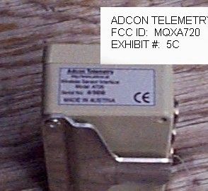
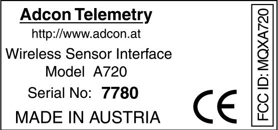
Adcon Telemetry http://www.adcon.at Wireless Sensor Interface Serial No: XXXXX MADE IN AUSTRIA Model A720 FCC ID: MQXA720
ID Label/Location Info
ADCON TELEMETRY INC. FCC ID: MQXA720 FCC ID LABEL LOCATION – TO BE PLACED ON LEFT SIDE OF PRODUCT
Test Report
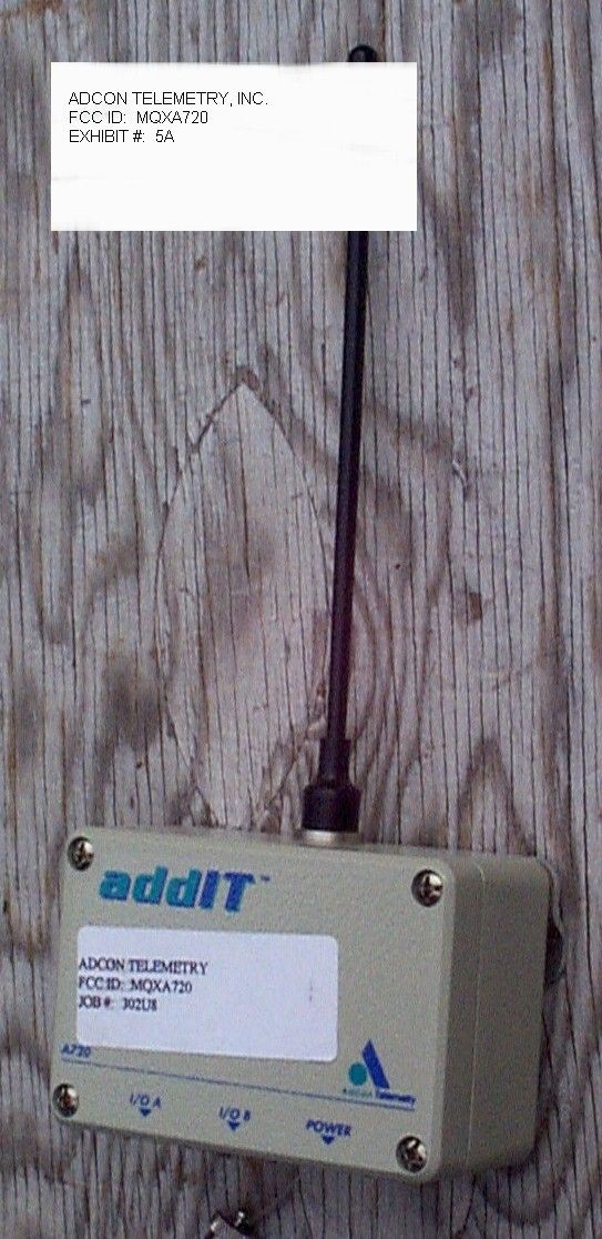
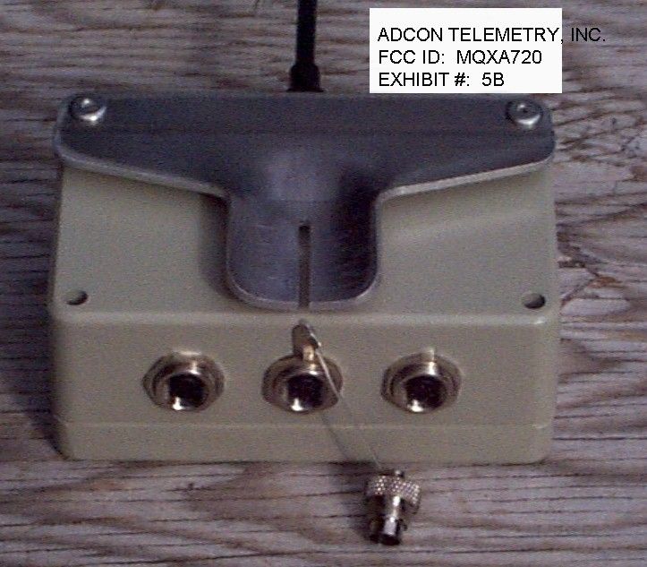
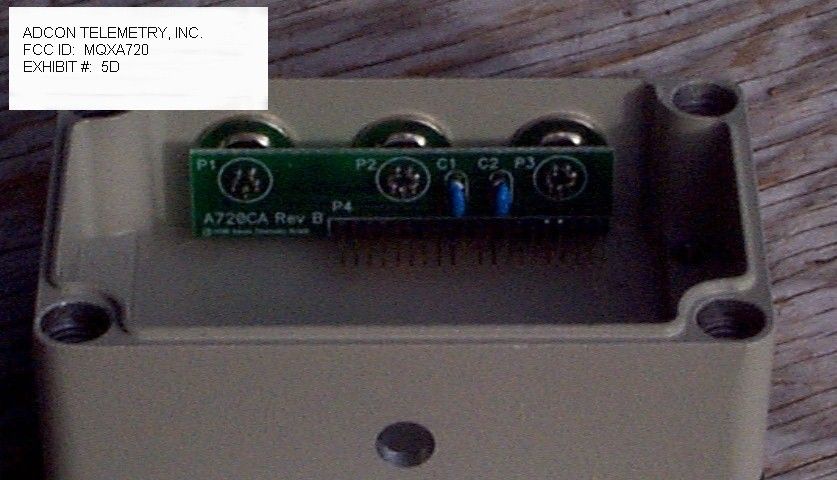
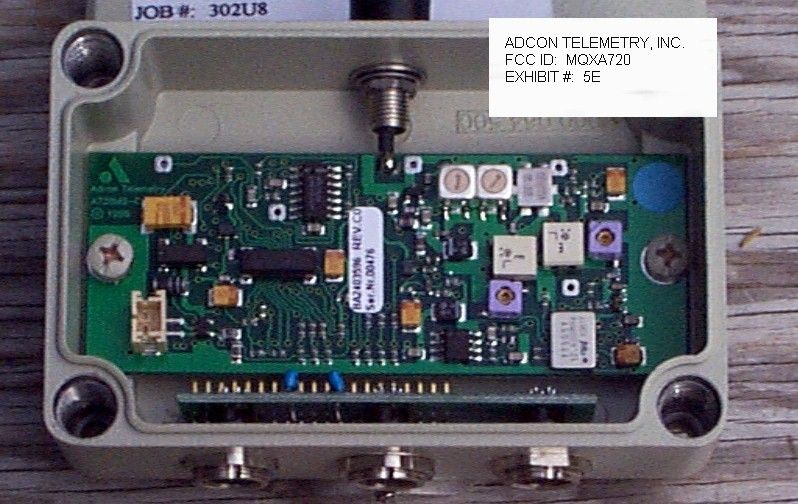
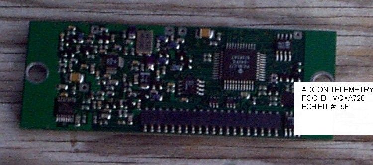
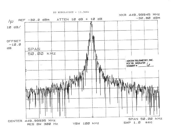
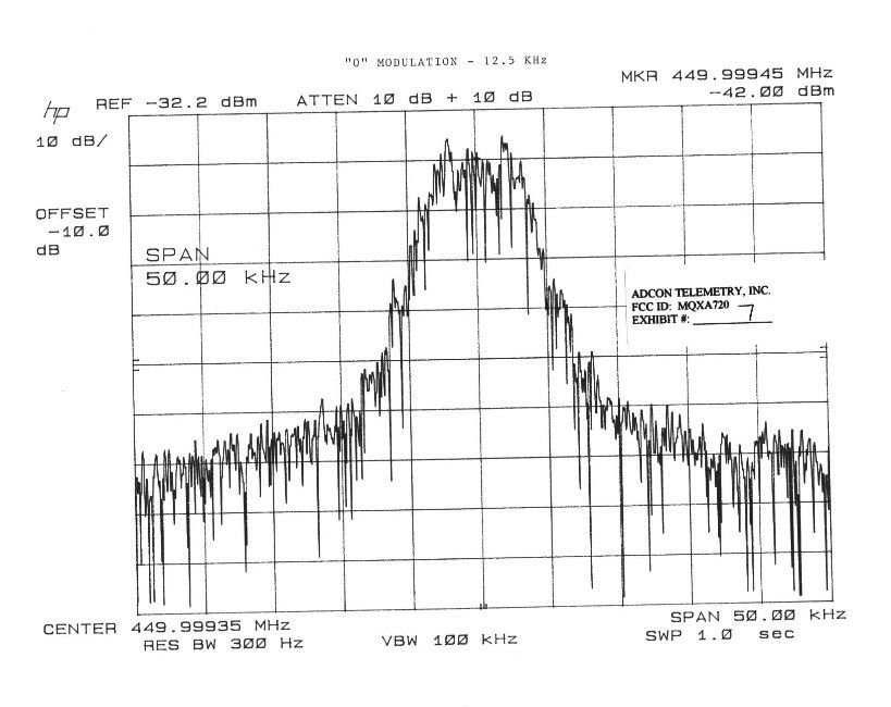
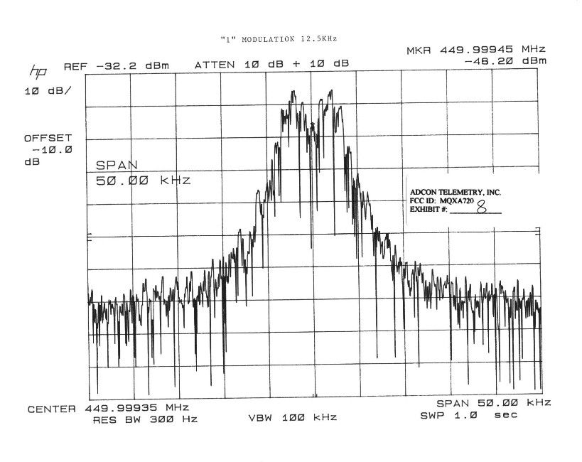
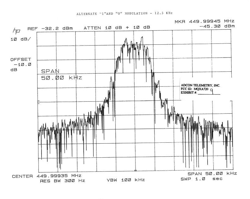
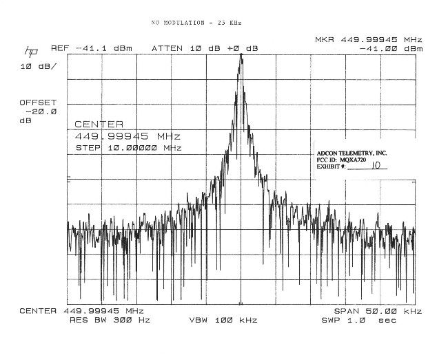
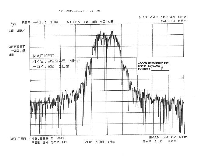
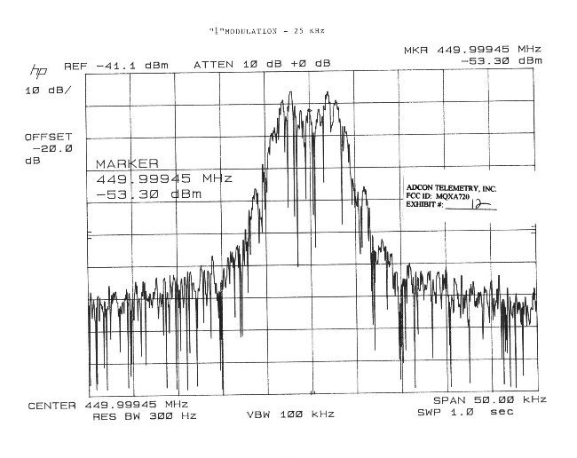
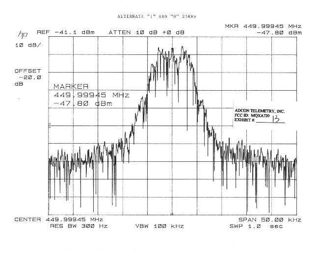
TABLE OF CONTENTS LIST APPLICANT: ADCON TELEMETRY, INC. FCC ID: MQXA720 TEST REPORT CONTAINING: PAGE 1......COVER SHEET - GENERAL INFORMATION & TECHNICAL DESCR. PAGE 2......TECHNICAL DESCRIPTION CONTD. AND RF POWER OUTPUT PAGE 3......RF POWER OUTPUT CONTD. & MODULATION CHARACTERISTICS PAGE 4......OCCUPIED BANDWIDTH PAGE 5......SPURIOUS EMISSIONS AT ANTENNA TERMINALS AND FIELD STRENGTH OF SPURIOUS EMISSIONS PAGE 6......FREQUENCY STABILITY PAGE 7......CERTIFICATION OF TECHNICAL DATA PAGE 8......LIST OF TEST EQUIPMENT EXHIBITS CONTAINING: EXHIBIT 1......POWER OF ATTORNEY LETTER EXHIBIT 2......FCC ID LABEL SAMPLE EXHIBIT 3......SKETCH OF FCC ID LABEL LOCATION EXHIBIT 4......SCHEMATIC EXHIBIT 5A.....EXTERNAL FRONT VIEW PHOTO EXHIBIT 5B.....EXTERNAL REAR VIEW PHOTO EXHIBIT 5C.....EXTERNAL SIDE VIEW PHOTO EXHIBIT 5D.....INTERNAL COMPONENT SIDE - SMALL BOARD EXHIBIT 5E.....INTERNAL COMPONENT SIDE - MAIN BOARD EXHIBIT 5D.....INTERNAL SOLDER SIDE - MAIN BOARD EXHIBIT 6......OCCUPIED BANDWIDTH - CW - 12.5KHz EXHIBIT 7......OCCUPIED BANDWIDTH - "0" MODULATION 12.5KHz EXHIBIT 8......OCCUPIED BANDWIDTH - "1'S" MODULATION 12.5KHz EXHIBIT 9......OCCUPIED BANDWIDTH - ALTERNATELY "0" & "1" 12.5KHz EXHIBIT 10.....OCCUPIED BANDWIDTH - CW - 25KHz EXHIBIT 11.....OCCUPIED BANDWIDTH - "0" MODULATION 25KHz EXHIBIT 12.....OCCUPIED BANDWIDTH - "1'S" MODULATION 25KHz EXHIBIT 13.....OCCUPIED BANDWIDTH - ALTERNATELY "0" & "1" 25KHz TECHNICAL MANUAL CONTAINING: BLOCK DIAGRAM............PAGE 6 TUNING PROCEDURE.........PAGES 12-13 CIRCUIT DESCRIPTIONS.....PAGES 20-21 PARTS LIST...............PAGES 24-27 CRYSTAL SPECIFICATION....PAGE 28 ADDITIONAL PHOTOGRAPHS...PAGE 29-33 INSTRUCTIONS.............PAGES 34-51 APPLICANT: ADCON TELEMETRY, INC. FCC ID: MQXA720 REPORT #: F:\CUS\A\ADCON\ADC302U8.RPT PAGE: TABLE OF CONTENTS GENERAL_INFORMATION_REQUIRED FOR_TYPE_ACCEPTANCE 2.983 (a,b,c) ADCON TELEMETRY, INC. will sell the MQXA720, in quantity, for use under FCC RULES PART 90.217(a). 2.983 (d) TECHNICAL_DESCRIPTION (1) ALLOWED AUTHORIZED BANDWIDTH = 11.25KHz. 90.209(b)(5) Bn=2M+2DK M = 1500/2 = 750 D = 3.0KHz (Peak Deviation) K=1 Bn = 2(.75K) + 2(3.0K)(1) = 1.5K + 6.0K = 7.5K This transmitter uses MSK(MINIMUM SHIFT KEYING). Type of Emission: 7K5F1D (2) ALLOWED AUTHORIZED BANDWIDTH = 20.0KHz. 90.209(b)(5) Bn=2M+2DK M = 1500/2 = 750 D = 3.2KHz (Peak Deviation) K=1 Bn = 2(.75K) + 2(3.2K)(1) = 1.5K + 6.4K = 7.9K This transmitter is frequency modulated F2d using two(2) different tones, 1900Hz & 3000Hz. Type of Emission: 7K9F1D ALLOWED AUTHORIZED BANDWIDTH = 40KHz (2) Frequency Range: Part 90: 432-470MHz (3) Power Range and Controls:Power is has no controls. (4) Maximum Output Power Rating: 120 Milli-Watts into a 50 ohm resistive load. (5) DC Voltages and Current into Final Amplifier: Not Applicable. (6) Function of each electron tube or semiconductor device or other active circuit device: APPLICANT: ADCON TELEMETRY, INC. FCC ID: MQXA720 REPORT #: F:\CUS\A\ADCON\ADC302U8.RPT PAGE #: 1 2.983(d) (7) Complete Circuit Diagrams: The circuit diagram is in 7. The block diagram is in 5. The part list is in PAGES 24-27 OF TECHNICAL MANUAL. (8) Instruction book. The instruction manual is in- cluded as PAGES 34-51 OF TECHNICAL MANUAL (9) Tune-up procedure. The tune-up procedure is given in PAGES 12-13 IN TECHNICAL MANUAL. (10) Description of all circuitry and devices provided for determining and stabilizing frequency. The transmitter frequency is controlled by a crystal, the crystal specifications are included in PAGE 28 OF TECHNICAL MANUAL. (11) Description of any circuits or devices employed for suppression of spurious radiation, for limit- ing modulation, and for limiting power. This circuitry is described in &cirdes&. Limiting Modulation: The transmitter audio circuitry is described in the Technical documentation. Limiting Power: There is no provision for limiting power. (12) Digital modulation. This unit does use digital modulation. 2.983(e) The data required by 2.985 through 2.997 is sub- mitted below. 2.985(a) RF_power_output. ERP was measured by connecting a signal generator to a dipole antenna and adjusting the level to produce the same field strength at the UUT. APPLICANT: ADCON TELEMETRY, INC. FCC ID: MQXA720 REPORT #: F:\CUS\A\ADCON\ADC302U8.RPT PAGE #: 2 MQXA720 R.F. POWER OUTPUT HP Spectrum Analyzer /-------\ /-----------------\ | | | | TRANSMITTER | | | | | UNDER TEST WITH | \--| | | INTERNAL ANTENNA| | | | \-----------------/ | | | | | \-------/ |?- 3.0 meters---?| /-------------\ | SIGNAL | DIPOLE | Tuned, Calibrated | GENERATOR | ANTENNA | Antenna which may | |----------/ be raised from 1 \-------------/ to 4 meters above ground and changed in polarization Equipment placed 1 meter above ground on a rotatable platform. The center of the Dipole antenna at the center of the platform and the output of the signal generator adjusted to produce the same meter reading as measured for the fundamental in the radiated emissions test. 2.987(a)(b) Modulation_characteristics: AUDIO_FREQUENCY_RESPONSE Not required. AUDIO_LOW_PASS_FILTER Not required this part. 2.987(b) Audio_input_versus_modulation Not applicable because there is no I/O port. APPLICANT: ADCON TELEMETRY, INC. FCC ID: MQXA720 REPORT #: F:\CUS\A\ADCON\ADC302U8.RPT PAGE #: 3 MQXA720 2.989(c) Occupied_bandwidth: Data in the plots show that the 30 dB occuppied band- width is less than 20KHz. The plots show the transmit- ter modulated with the worst(greatest bandwidth) case combination of controls. Test procedure diagram OCCUPIED BANDWIDTH MEASUREMENT NEAR FIELD /------------\ PROBE | | /----\ | Transmitter| |____|------\ | under test | \----/ | \------------/ | || || /------------\ /-----------\ |||| | Audio | | Spectrum | | Oscillator | | Analyzer | | | \-----------/ \------------/ REQUIREMENT: PART 90.217 EMISSION BANDWIDTH PLUS FREQUENCY STABILITY <40KHz AT 30dB. APPLICANT: ADCON TELEMETRY, INC. FCC ID: MQXA720 REPORT #: F:\CUS\A\ADCON\ADC302U8.RPT PAGE #: 4 2.991 Spurious_emissi…
Text truncated - open the document above for the full version.
Contact Information
Applicant
Lix Paulian(R&D Systems Designer)
Technical Contact
TIMCO ENGINEERING, INC.S. S. SANDERS
[email protected]888-472-2424
25355 W. NEWBERRY ROAD · NEWBERRY, Florida · United States
Non-Technical Contact
TIMCO ENGINEERING, INC.SHARON A HOFFMAN
[email protected]888-472-2424
Test Firm
Timco Engineering, Inc.Sid Sanders
Technical Specifications
| # | Rule Parts | Frequency Range | Power Output | Emission | Tolerance |
|---|---|---|---|---|---|
| 1 | 90.217(b) | 432 MHz - 470 MHz | 12.00 mW | 12K4F3D | 0.0005000000 % |
Other Applications from Adcon Telemetry Inc
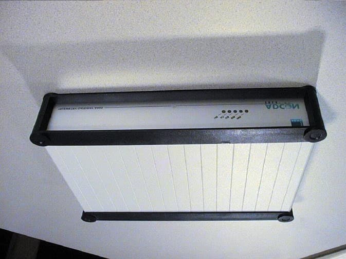
MQXA840
Jan 16, 2002Telemetry Gateway
Equipment Class
JBP - Part 15 Class B Computing Device Peripheral
MQXB900SS-500
Jan 01, 2002FM Radio Transceiver Module
Equipment Class
DSS - Part 15 Spread Spectrum Transmitter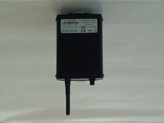
MQXSMLIP
Nov 14, 2001Wireless Modem
Equipment Class
DSS - Part 15 Spread Spectrum Transmitter
MQX550660-001
Oct 29, 2001Wireless STAT TX
Equipment Class
DXX - Part 15 Low Power Communication Device Transmitter
MQX550205-001
Oct 29, 2001Wireless TTX
Equipment Class
DXX - Part 15 Low Power Communication Device Transmitter