MQXSMLIPWireless Modem
Adcon Telemetry Inc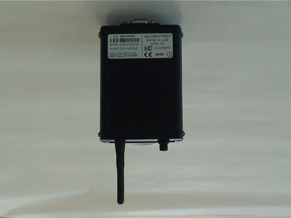
Click to zoom
Application Details
- Equipment Class
- DSS - Part 15 Spread Spectrum Transmitter
- Date of Grant
- Nov 14, 2001
- Application Purpose
- Original Equipment
- Date of Application
- Nov 14, 2001
- Equipment Note
- Wireless Modem
- Frequency Range
- 2410.00000000 - 2470.00000000
- Company
- Adcon Telemetry Inc
- Country
- United States
Documents & Files
Document Text
Text extracted from the exhibit documents filed with the FCC. Open a document above to read the original.
External Photos
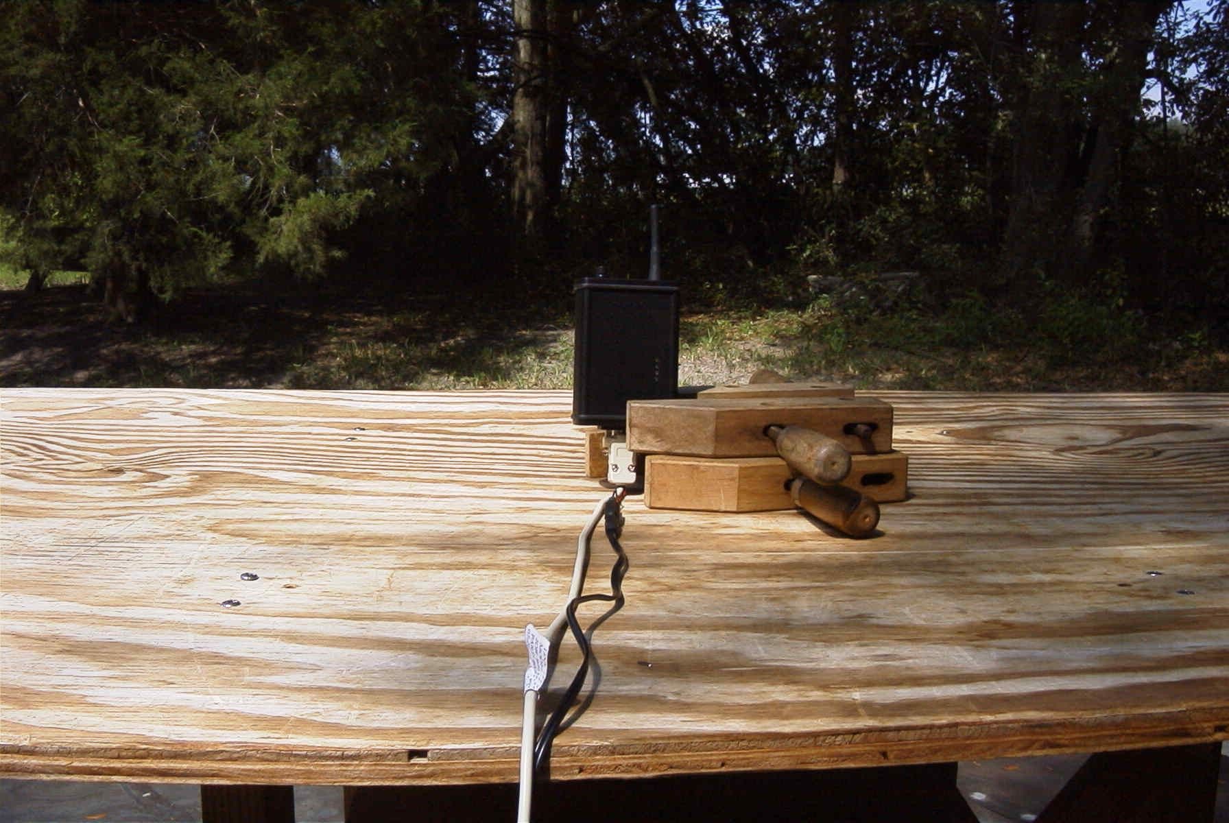
TRM SML2400_V1_3.docpage 9 of 2008/27/01 4:46 PM CONFIDENTIAL ADCON RF Technology Zekeringstraat 40, 1014 BT AMSTERDAM, THE NETHERLANDS tel +31 20 4204200 fax +31 4209652 3 Photographs of SML2400 3.1 SML2400, Front view TRM SML2400_V1_3.docpage 10 of 2008/27/01 4:46 PM CONFIDENTIAL ADCON RF Technology Zekeringstraat 40, 1014 BT AMSTERDAM, THE NETHERLANDS tel +31 20 4204200 fax +31 4209652 3.2 SML2400, Back view TRM SML2400_V1_3.docpage 12 of 2008/27/01 4:46 PM CONFIDENTIAL ADCON RF Technology Zekeringstraat 40, 1014 BT AMSTERDAM, THE NETHERLANDS tel +31 20 4204200 fax +31 4209652 3.4 SML2400, Top view 3.5 SML2400, Bottom view TRM SML2400_V1_3.docpage 13 of 2008/27/01 4:46 PM CONFIDENTIAL ADCON RF Technology Zekeringstraat 40, 1014 BT AMSTERDAM, THE NETHERLANDS tel +31 20 4204200 fax +31 4209652 3.6 SML2400, Left view 3.7 SML2400, Right view
ID Label/Location Info
This device complies with Part 15 of the FCC rules.Operation is subject to the following two conditions: (1)this device may not cause harmful interference and (2)this device must accept any interference received, including interference that may cause undesired operation. M. Coenen 13-11-2001 SML2400IP Polyester Sticker M2400SMLIP (64 X 25) SIZE Project Nr. DWG NO REV A4 245 V2 SCALE mm. SHEET 1 OF 1 DRAWN: DATE: Sizes in: (C) 2001 Adcon RF TECHNOLOGY B.V. Zekeringstraat 40, 1014 BT AMSTERDAM THE NETHERLANDS Tel: +31 (0)20 4204200 Fax: +31 (0)20 420 9652 Internet: www.adcon.com ?? mm Uitvoering sticker: - Gemetaliseerd polyester met mat polyester laminaat.- Bedrukt in : 1 Kleur, zwart.- Uitvoering : 1 Soort- Wikkeling : 1- Kerndiameter: 76 mm- Roldiameter: ca. 110 mm- Hoeken: Rond 1mm, gelijk aan vorige versie.- Oplopend serienummer.- Barcode geeft serienummer weer ( SML000004 ).- Barcode type: 128 64 mm FCC Opmerkingen over veranderingen:Zwarte omlijning is voor het aangeven van debuitenmaat, moet niet geprint worden.FCC logo is veranderd in de volgende tekst:FCC IDLetter type tekst: grootte als "www.adcon.com".De grootte in deze tekening is nu 6pt,Lettertype: ArialDe hoogte van de sticker is nog niet ingevuld.Dit is afhankelijk van de extra tekst.
ID Label/Location Info
TRM SML2400_V1_3.docpage 11 of 2008/27/01 4:46 PM CONFIDENTIAL ADCON RF Technology Zekeringstraat 40, 1014 BT AMSTERDAM, THE NETHERLANDS tel +31 20 4204200 fax +31 4209652 3.3 SML2400, Label Information
Internal Photos
TRM SML2400_V1_3.docpage 14 of 2008/27/01 4:46 PM CONFIDENTIAL ADCON RF Technology Zekeringstraat 40, 1014 BT AMSTERDAM, THE NETHERLANDS tel +31 20 4204200 fax +31 4209652 3.8 SML2400 RF-PCB, top view with screen 3.9 SML2400 RF-PCB, top view with screen & lid TRM SML2400_V1_3.docpage 15 of 2008/27/01 4:46 PM CONFIDENTIAL ADCON RF Technology Zekeringstraat 40, 1014 BT AMSTERDAM, THE NETHERLANDS tel +31 20 4204200 fax +31 4209652 3.10 SML2400 RF-PCB, bottom view TRM SML2400_V1_3.docpage 16 of 2008/27/01 4:46 PM CONFIDENTIAL ADCON RF Technology Zekeringstraat 40, 1014 BT AMSTERDAM, THE NETHERLANDS tel +31 20 4204200 fax +31 4209652 3.11 SML2400 Digital-PCB, top view 3.12 SML2400 Digital-PCB, bottom view TRM SML2400_V1_3.docpage 17 of 2008/27/01 4:46 PM CONFIDENTIAL ADCON RF Technology Zekeringstraat 40, 1014 BT AMSTERDAM, THE NETHERLANDS tel +31 20 4204200 fax +31 4209652 3.13 SML2400, RF-PCB & Digital PCB
Operational Description
9 Chapter 1. Introduction The SML2400 IP is a complete spread spectrum transceiver module, that operates in the license-free, 2.4 GHz ISM band. The spread spectrum technology in combination with an intelligent protocol ensures safe, robust and reliable transmissions. Especially in difficult or hostile environ- ments where interfering and reflective signals can occur, the SML2400 IP offers a solution where other products fail. The SML2400 IP is approved under ETSI and FCC and may be used worldwide. The SML2400 IP fea- tures the ability to change the system settings with AT-commands via RS- 232 port communication. This makes it possible to change both system and communication protocols instantly. Description The SML2400 IP consists of a black metal case with one connector, four LED indicators, a fixed antenna and an on/off switch. The LEDs indicate the different status of the SML2400 IP. On the bottom of the SML2400 IP is a RS-232 DB9 female connector. CHAPTER 1 Introduction 10 Figure 1. The SML2400 IP The product also contains: •a RS-232 male-female connector with an integrated power supply connector •a 220V – 9V DC power adapter (110V – 9V for the U.S.) •A CD-ROM containing the manual and the SML2400 IP Configuration Program System Indicators The SML2400 IP is equipped with four LEDs: 1. On: This LED turns off when the system powers down (Standby/Sleep). 2. Link: It indicates if a link is established in Secured Mode. 3. Tx: It indicates that data is being transmitted. 4. Rx: It indicates that data is being received. SML 2400 IP W IRELESS MODEM Fixed Antenna On/Off-Switch LED Indicators RS-232 Female Connector with Integrated Power Supply Connector CHAPTER 1 Applications 11 Figure 2. LED Indicators Applications In many cases the SML2400 IP is used to connect a fixed device (PC, sen- sor, modem) to a portable device (PDA, laptop, remote control unit). Some sample applications for the SML2400 IP are: 1. Point to Point configuration 2. Remote control 3. Telemetry applications for sensors and indicators 4. Wireless NULL modem connection 5. Wireless baud rate converter The SML2400 IP is equipped with a number of factory templates. For connecting fixed devices to portable devices, you can use factory setting #2 (this is the default setting). This enables the portable device to com- municate with the PC using either the SML2400 IP Configuration Pro- gram or HyperTerminal. It gives you the opportunity to become familiar with the SML2400 IP and permits, for instance, the measuring of the cov- erage field by the signal quality at different locations. This can be done simply by walking around with a laptop and testing the quality of the PC link from various points. LED #1: On LED #2: Link LED #3: Tx LED #4: Rx CHAPTER 1 Introduction 12 General Specifications •Channel frequencies: 2410 – 2470 MHz •Number of channels: 16 •RF bandwidth: 6 MHz (99% of power) •Frequency selection: 4 MHz step •Spread spectrum type : Direct Sequence Spread Spectrum •Modulation: DBPSK •Air data rate: 260 kbps •Spread code length: 15 chips •Chip rate: 3.8 Mcps •Radio power output: 14 dBm (max.) EIRP •Receiver sensitivity: –95 dBm •Data interface: RS-232 DB9 female connector •RS-232 data rate: 2400 ... 57600 bps •Range: 1000 m (line of sight) •Unit is IP64-Compliant: - Dust tight - Water splashed on the unit from any direction will have no harmful effect. •Conformity testing: - ETSI 300 328 - ETSI 300 826 - FCC part 15 Electrical Specifications •External power supply : 8.5 V to 10 V •Internal battery pack: 1600 mAh Rechargeable NiMH Batteries. Batteries need to be charged before first use. •Power consumption - with external power supply (including battery charging current): - Transmission: < 360 mA - Reception: < 265 mA - Standby: < 160 mA - Sleep: < 140 mA - battery powered - Transmission: < 310 mA CHAPTER 1 Embedded Software Features 13 - Reception: < 190 mA - Standby: < 25 mA - Sleep: < 210 μA •Operating temperature: –20° C to +60° C [–4° F to 140° F] Embedded Software Features •Point to Point - Burst Mode - Secured Mode •Sleep Mode (DTR down operated) •Power-Saving Interval Mode •ACK/NACK error correction with CRC error detection •Hayes-compatible command set Dimensions •Weight:380g •Length: 115 mm •Width:82mm •Height:32mm CHAPTER 1 Introduction 14 T Figure 3. Dimensions 0WARNING Do not use adapters other than the one(s) supplied with the product. These adapters are designed to supply 9 V. There are adapters in existence, which supply more than 9 V without a load. This device complies with Part 15 of the FCC Rules. Operation is subject to the following conditions: 1.The device may not cause harmful interference. 2.The device must accept any interference received, including interference that may cause undesired operation. 3.The antennas used for the transmitter must be installed as to provide a separation distance of at least 20 cm from all persons and must not be co-located or operated in conjunction with any other antenna or transmitter. End-users and any person responsible for installation must be provided with antenna installation instructions and transmitter operating conditions for satisfying RF exposure compliance. SML2400 IP WIRELESS MODEM 32 mm 115 mm 82 mm
Test Report
APPLICANT: ADCON TELEMETRY, INC. FCC ID: MQXSMLIP REPORT #: A\ADCON\818AU1\818AU1RPT.DOC PAGE #: TABLE OF CONTENTS APPLICANT: ADCON TELEMETRY, INC. FCC ID: MQXSMLIP TABLE OF CONTENTS TEST REPORT CONTAINING: PAGE 1.............TEST EQUIPMENT LIST & TEST PROCEDURE PAGE 2.............TEST PROCEDURES CONTD. PAGE 3.............6.0dB BANDWIDTH PAGE 4.............BANDEDGE PLOT PAGE 5.............POWER OUTPUT & MEHTOD OF MEASURING RF POWER OUTPUT PAGE 6.............METHOD OF MEASURING RF CONDUCTED SPURIOUS EMISSIONS & SPURIOUS EMISSIONS AT ANTENNA TERMINALS PAGE 7.............RADIATION INTERFERENCE TEST DATA PAGE 8.............METHOD OF MEASURING RADIATION INTERFERENCE PAGE 9-10..........POWER SPECTRAL DENSITY PAGE 11............PROCESSING GAIN EXHIBIT ATTACHMENTS: EXHIBIT 1...........CONFIDENTIALITY LETTER EXHIBIT 2...........FCC ID LABEL SAMPLE & LOCATION EXHIBIT 3A-3D.......EXTERNAL PHOTOGRAPHS EXHIBIT 4A-4D.......INTERNAL PHOTOGRAPHS EXHIBIT 5...........BLOCK DIAGRAM EXHIBIT 6A-6J.......SCHEMATICS EXHIBIT 7A-7F.......CIRCUIT DESCRIPTION EXHIBIT 8...........INSTRUCTION MANUAL EXHIBIT 9A-9I.......PROCESSING GAIN DATA EXHIBIT 10..........TEST SETUP PHOTOGRAPH APPLICANT: ADCON TELEMETRY, INC. FCC ID: MQXSMLIP REPORT #: A\ADCON\818AU1\818AU1RPT.DOC PAGE #: 1 OF 13 TEST EQUIPMENT LIST 1. Spectrum Analyzer: HP 8566B-Opt 462, S/N 3138A07786, w/ preselector HP 85685A, S/N 3221A01400, Quasi-Peak Adapter HP 8565OA, S/N 3303A01690 & Preamplifier HP 8449B-OPT H02, S/N 3008A00372 2. Biconnical Antenna: Eaton Model 94455-1, S/N 1057 3. Biconnical Antenna: Electro-Metrics Model BIA-25, S/N 1171 4. Log-Periodic Antenna: Electro-Metrics Model EM-6950, S/N 632 5. Log-Periodic Antenna: Electro-Metrics Model LPA-30, S/N 409 6. Double-Ridged Horn Antenna: Electro-Metrics Model RGA-180, 1-18 GHz, S/N 2319 7. 18-26.3GHz Systron Donner Standard Gain Horn #DBE-520-20 8. Horn 40-60GHz: ATM Part #19-443-6R 9. Line Impedance Stabilization Network: Electro-Metrics Model EM-7820, w/NEMA Adapter S/N 2682 10. Temperature Chamber: Tenney Engineering Model TTRC, S/N 11717-7 11. Frequency Counter: HP Model 5385A, S/N 3242A07460 12. Peak Power Meter: HP Model 8900C, S/N 2131A00545 13. Open Area Test Site #1-3meters 14. Signal Generator: HP 8640B, S/N 2308A21464 15. Signal Generator: HP 8614A, S/N 2015A07428 16. Passive Loop Antenna: EMCO Model 6512, 9KHz to 30MHz, S/N 9706-1211 17. Dipole Antenna Kit: Electro-Metrics Model TDA-30/1-4, S/N 153 18. AC Voltmeter: HP Model 400FL, S/N 2213A14499 19. Digital Multimeter: Fluke Model 8012A, S/N 4810047 20. Digital Multimeter: Fluke Model 77, S/N 43850817 21. Oscilloscope: Tektronix Model 2230, S/N 300572 TEST PROCEDURE GENERAL: This report shall NOT be reproduced except in full without the written approval of TIMCO ENGINEERING, INC. Shielded interface cables were used in all cases except for cables connecting to the telephone line and the power cords. A test program was run which simulated a normal data transmission on a network. APPLICANT: ADCON TELEMETRY, INC. FCC ID: MQXSMLIP REPORT #: A\ADCON\818AU1\818AU1RPT.DOC PAGE #: 2 OF 11 TEST PROCEDURES CONTINUED BANDWIDTH 6.0dB: The measurements were made with the spectrum analyz- er's resolution bandwidth(RBW)=1.0MHz and the video bandwidth(VBW) =3.0MHz and the span set as shown on the plot. POWER OUTPUT: The RF power output was measured at the antenna feed point using a peak power meter. ANTENNA CONDUCTED EMISSIONS: The RBW=100KHz, VBW=300KHz and the span set to 10.0MHz and the spectrum was scanned from 30MHz to the 10th Harmonic of the fundamental. Above 1.0GHz the resolution bandwidth was 1.0MHz and the VBW = 3.0MHz and the span to 50MHz. RADIATION INTERFERENCE: The test procedure used was ANSI STANDARD C63.4-1992 using a HEWLETT PACKARD spectrum analyzer with a prese- lector. The bandwidth(RBW) of the spectrum analyzer was 100kHz up to 1GHz and 1.0MHz above 1GHz with an appropriate sweep speed. The VBW above 1.0GHz was = 3.0MHz. The analyzer was calibrated in dB above a microvolt at the output of the antenna. The ambient temperature of the UUT was 83°F with a humidity of 65%. PRODUCT DESCRIPTION: 2.4 GHz DSSS transceiver using a fixed antenna. APPLICANT: ADCON TELEMETRY, INC. FCC ID: MQXSMLIP REPORT #: A\ADCON\818AU1\818AU1RPT.DOC PAGE #: 3 OF 11 APPLICANT: ADCON TELEMETRY, INC. FCC ID: MQXSMLIP NAME OF TEST: 6.0dB BANDWIDTH RULES PART NUMBER: 15.247(a)(2) REQUIREMENTS: The 6.0dB bandwidth must be greater than 500 kHz. MEASUREMENT: The 6.0dB bandwidth measured @ 2470.00MHz was 3.48MHz. THE 6.0dB bandwidth measure @ 2408.00MHz was 4.12MHz. MEASUREMENT DATA: See plot below 6.0 dB BANDWIDTH PLOT APPLICANT: ADCON TELEMETRY, INC. FCC ID: MQXSMLIP REPORT #: A\ADCON\818AU1\818AU1RPT.DOC PAGE #: 4 OF 11 APPLICANT: ADCON TELEMETRY, INC. FCC ID: MQXSMLIP NAME OF TEST: RADIATED SPURIOUS EMISSIONS INTO ADJACENT RESTRICTED BAND REQUIREMENTS: Emissions that fall in the restricted bands (15.205). These emissions must be less than or equal to 500 uV/m (54 dBuV/m). TEST PROCEDURE: An in band field strength measurement of the fundamental emissions using the RBW and detector function required by C63.4-2000 and FCC rules. The procedure was repeated with an average detector and a plot made. The calculated field strength in the adjacent restricted band is presented below. .10 dBuV - from Plot + 29.21 dB - ACF + 1.10 dB - Coax Loss ___________ 30.41 dBuV Bandedge Plot APPLICANT: ADCON TELEMETRY, INC. FCC ID: MQXSMLIP REPORT #: A\ADCON\818AU1\818AU1RPT.DOC PAGE #: 5 OF 11 APPLICANT: ADCON TELEMETRY, INC. FCC ID: MQXSMLIP NAME OF TEST: POWER OUTPUT RULES PART NUMBER: 15.247(b) 1.0Watt or +30dBm MEASUREMENT: 0.013 WATTS 15.247(c) Method of Measuring RF Power output: The Peak power Sensor was connected in place of the antenna. /--------\ |HP | |PEAK | |PWR MTR | |8900C | \--------/ | /-----------\ /-----------------\ | | UUT | | PEAK POWER | | | Mounted |------| SENSOR HP84811A |------------------/ | in | \-----------------/ | Laptop | | computer | \-----------…
Text truncated - open the document above for the full version.
Test Report
Measurement report on Processing Gain SML2400IP Version 1.0 October 15 th 2001 SML2400IP processing gain measurement V1.0 Page 2 of 910/16/01 © Adcon RF Technology B.V. Zekeringstraat 40 1014 BT Amsterdam The Netherlands tel +31 20 4204200 fax +31 20 4209652 e-mail [email protected] http://www.adcon.com confidential Processing gain measurement SML2400IP .................................................................................................... 3 1.Scope................................................................................................................................................... 3 2.Summary results.................................................................................................................................. 3 3.Description of test ............................................................................................................................... 4 3.1. Equipment list .................................................................................................................................. 4 3.2. Test setup ......................................................................................................................................... 4 3.3. Justification of 250kHz measurement bandwidth ............................................................................ 5 4.Measurement results ........................................................................................................................... 8 5.Conclusions......................................................................................................................................... 9 SML2400IP processing gain measurement V1.0 Page 3 of 910/16/01 © Adcon RF Technology B.V. Zekeringstraat 40 1014 BT Amsterdam The Netherlands tel +31 20 4204200 fax +31 20 4209652 e-mail [email protected] http://www.adcon.com confidential Processing gain measurement SML2400IP 1. Scope For the purpose of FCC type approval (FCC part 15, section 15.247(e)) the processing gain has been measured. Processing gain is defined as the difference in signal to noise ratio between the input and output of the demodulator. This difference can be measured by measuring the difference in signal to noise ratio with the despreading switched on and off. The theoretical processing gain of the SML2400IP is 11.7dB (10*Log(Codelength=15)). 2. Summary results The processing gain was found to be between 10.2dB and 12.7dB. SML2400IP processing gain measurement V1.0 Page 4 of 910/16/01 © Adcon RF Technology B.V. Zekeringstraat 40 1014 BT Amsterdam The Netherlands tel +31 20 4204200 fax +31 20 4209652 e-mail [email protected] http://www.adcon.com confidential 3. Description of test In FCC part 15, section 15.247(e) two measurement methods are described to measure the processing gain of the unit under test. For the measurement of the processing gain of the SML2400IP method (1) is used. “15.247(e) The processing gain of a direct sequence system shall be at least 10 dB. The processing gain represents the improvement to the received signal-to-noise ratio, after filtering to the information bandwidth, from the spreading/despreading function. The processing gain may be determined using one of the following methods: (1) As measured at the demodulated output of the receiver: the ratio in dB of the signal-to- noise ratio with the system spreading code turned off to the signal-to-noise ratio with the system spreading code turned on.” 3.1. Equipment list - Rohde Schwarz SMIQ03B signal generator with I/Q modulation inputs - Yokogawa FC300 arbitrary signal generator (used to modulate the SMIQ03B) - Rohde Schwarz FPS30 Spectrum Analyzer - Adcon SML2400IP unit 3.2. Test setup The SMIQ03B was modulated by the FC300 that generated the PN sequence. This combination served as a reference transmitter. The SML2400IP under test was set at a fixed AGC level. The output of the despreader was monitored with the spectrum analyzer. The measurements of this document were taken after the despreader, but before the digital filtering occurs. There’s no signal physically available to monitor after the digital filtering, so the unfiltered signal was measured in a bandwidth equal to the digital filtering bandwidth to include the effects of digital filtering (see later chapter “Justification of 250kHz measurement bandwidth”). The SML2400IP was setup in such a way that the despreading could be switched on and off. All measurements were carried out well above the noise floor of the used equipment. SMIQ03B FC300 SML2400IP -50dBm PN Fixed AGC SA SML2400IP processing gain measurement V1.0 Page 5 of 910/16/01 © Adcon RF Technology B.V. Zekeringstraat 40 1014 BT Amsterdam The Netherlands tel +31 20 4204200 fax +31 20 4209652 e-mail [email protected] http://www.adcon.com confidential The following picture shows the output spectrum of the reference transmitter measured at the SML2400IP RF input: A Att10dBRef -39.3dBm RBW100 kHz VBW300 kHz * * *1RM CLRWR SWT2.5ms Center2.41GHzSpan12.12MHz1.212MHz/ PRN -130 -120 -110 -100 -90 -80 -70 -60 -50 -40 Bandwidth6MHz Reference0.00dBm NONETxChannel Power-53.30dBm Marker1[T1] -6 4.44dBm 2.410000000 GHz 1 C0 C0 Figure 1. Output spectrum of the reference transmitter 3.3. Justification of 250kHz measurement bandwidth As mentioned before, the measurements were carried out in a 250kHz bandwidth to include the effects of the digital filter. The following section describes why this is necessary. A received signal is multiplied by a reference (PN code) with the same code and (assuming that the transmitter’s code and the receiver’s code are synchronous) the carrier inversions transmitted are removed and the original carrier is restored. This narrow band restored carrier can then flow through the band pass filter designed to pass only the baseband-modulated carrier. Undesired signals are also treated in the same process of multiplication by the receiver’s reference, that…
Text truncated - open the document above for the full version.
Contact Information
Applicant
Lix Paulian(R&D Systems Designer)
Test Firm
Timco Engineering, Inc.S Sanders
Technical Specifications
| # | Rule Parts | Frequency Range | Power Output |
|---|---|---|---|
| 1 | 15C | 2.41 GHz - 2.47 GHz | 13.00 mW |
Other Applications from Adcon Telemetry Inc
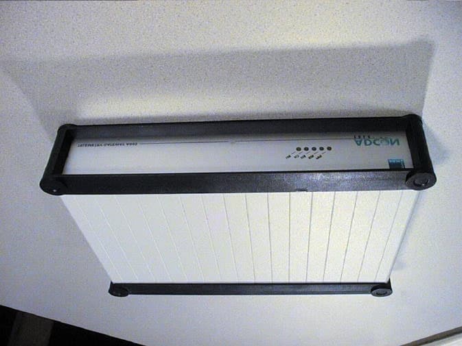
MQXA840
Jan 16, 2002Telemetry Gateway
Equipment Class
JBP - Part 15 Class B Computing Device Peripheral
MQXB900SS-500
Jan 01, 2002FM Radio Transceiver Module
Equipment Class
DSS - Part 15 Spread Spectrum Transmitter
MQX550660-001
Oct 29, 2001Wireless STAT TX
Equipment Class
DXX - Part 15 Low Power Communication Device Transmitter
MQX550205-001
Oct 29, 2001Wireless TTX
Equipment Class
DXX - Part 15 Low Power Communication Device Transmitter
MQXD900SS-20-A
Aug 27, 2001DSS - Part 15 Spread Spectrum Transmitter
Equipment Class
DSS - Part 15 Spread Spectrum Transmitter