MQXA840Telemetry Gateway
Adcon Telemetry Inc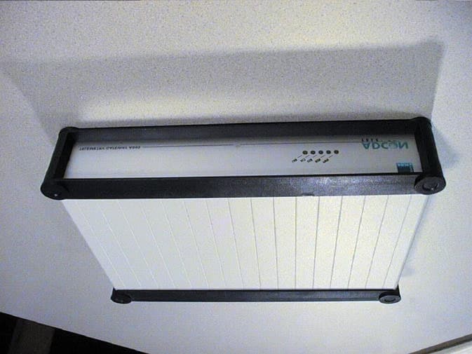
Click to zoom
Application Details
- Equipment Class
- JBP - Part 15 Class B Computing Device Peripheral
- Date of Grant
- Jan 16, 2002
- Application Purpose
- Original Equipment
- Date of Application
- Jan 16, 2002
- Equipment Note
- Telemetry Gateway
- Company
- Adcon Telemetry Inc
- Country
- United States
Documents & Files
Document Text
Text extracted from the exhibit documents filed with the FCC. Open a document above to read the original.
Users Manual
ADCON TELEMETRY Base Station Telemetry Gateway A840 and Wireless Modem A440 User Guide SMART WIRELESS SOLUTIONS ADCON TELEMETRY ADCON TELEMETRY AG INKUSTRASSE 24 A-3400 KLOSTERNEUBURG AUSTRIA TEL: +43 (2243) 38 280-0 FAX: +43 (2243) 38 280-6 http://www.adcon.at ADCON TELEMETRY INC 1001 YAMATO ROAD SUITE #305, BOCA RATON FL 33431 USA TEL: +1 (561) 989-5309 FAX: +1 (561) 989-5310 http://www.adcon.com ADCON TELEMETRY SRL BD. ION IONESCU DELABRAD 8 R-71592 BUCHAREST ROMANIA TEL: +40 (1) 490-6083 FAX: +40 (1) 490-6086 http://www.adcon.ro Proprietary Notice: The Adcon logo, the A720 and A730 series, addIT™, addWAVE™, the A840 series and Teleme- try Gateway, addVANTAGE®, and addVANTAGE Lite are trademarks or registered trademarks of Adcon Telemetry. All other registered names used throughout this publication are trademarks of their respective owners. Neither the whole nor any part of the information contained in this publication may be repro- duced in any material form except with the prior written permission of Adcon Telemetry. This publication is intended only to assist the reader in the use of the product. Adcon Telemetry shall not be liable for any loss or damage arising from the use of any information in this publica- tion, or any error or omission in such information, or any incorrect use of the product. Document Release 1.2, September 2001 Copyright ©2001 by Adcon Telemetry. All rights reserved. 3 Table of Contents Chapter 1. Introduction _________________________________7 Chapter 2. System Setup ________________________________9 Package Contents _______________________________________9 Installation _____________________________________________9 Installing the Outdoor Unit __________________________ 12 Installing the Indoor Unit ____________________________ 13 Initializing the Base Station __________________________ 14 LED Indicators ________________________________________ 15 Linux Mode ________________________________________ 15 LAN and ACT ___________________________________ 15 USR and RUN ___________________________________ 15 PWR ___________________________________________ 16 Hermit Mode ______________________________________ 16 Chapter 3. Advanced Functions________________________ 17 Administrative Tasks at the System Level _________________ 17 Stopping and Starting the telemetry gateway __________ 18 4 Changing Passwords ________________________________ 19 Losing a Password __________________________________ 20 Software Upgrades__________________________________ 21 Upgrading the bootloader ________________________ 21 To upgrade the system ___________________________ 22 Operations at the Application Level ______________________ 23 Commands Accepted by the emu3ap Emulator_________ 23 Configuration Commands____________________________ 24 INSERT _________________________________________ 24 REPLACE _______________________________________ 24 DELETE_________________________________________ 24 ROUTE _________________________________________ 25 MASTER ________________________________________ 26 EXTEND ________________________________________ 26 SET Commands__________________________________ 26 SET TIME _______________________________________ 27 SET FREQ_______________________________________ 27 SET OWNID_____________________________________ 28 SET SLOT _______________________________________ 28 SET DELAY ______________________________________ 28 SET ECHO/NOECHO ____________________________ 29 Data Commands____________________________________ 29 GETBLOCK _____________________________________ 29 Administrative Commands ___________________________ 31 VER ____________________________________________ 31 TYPE ___________________________________________ 31 INSPECT________________________________________ 31 UPTIME_________________________________________ 32 NOP ___________________________________________ 32 HELP ___________________________________________ 32 QUIT ___________________________________________ 32 Direct Radio Commands _____________________________ 32 PING ___________________________________________ 33 REQUEST _______________________________________ 34 RSETIO _________________________________________ 35 PORT___________________________________________ 36 ANALOG _______________________________________ 36 5 B ______________________________________________ 36 RB _____________________________________________ 37 RBLIST _________________________________________ 37 RSET ___________________________________________ 38 Error Messages_____________________________________ 38 Frame Types _______________________________________ 39 The A730MD frames _____________________________ 39 Type 9__________________________________________ 39 The A720 (addIT) Frames _________________________ 42 Type 38 ________________________________________ 42 The A723 (addIT series 3) Frames __________________ 43 Type 39 ________________________________________ 44 The A733 (addWAVE) Frames _____________________ 45 Type 37 ________________________________________ 46 Frame Parsing Example _____________________________ 48 6 7 Chapter 1. Introduction This manual describes the use of the A840 Telemetry Gateway and A440 Wireless Modem combination. Due to their general nature, either unit can also be used independently, but such uses are beyond the scope of this manual. The manual teaches you how to use the telemetry gateway and the wireless modem as a base sta- tion for an Adcon wireless network. To build a network, you need one or more A730MD, A733, A720, or A723 remote telemetry units (RTUs), an A840/A440 base sta- tion, and the addVANTAGE software. For additional information concerning the RTUs and the addVANTAGE software, consult the respective user manuals. The A840 Telemetry Gateway is a low-power, battery-backed device that acts as an interface between an Adcon wireless net- work and one or more hosts running addVANTAGE or similar data acquisition software. The gateway is based on a powerful 32-bit processor running the Lin…
Text truncated - open the document above for the full version.
Block Diagram
6 Hardware delivered with a modem pre-installed). For additional details, please refer to the at- tached schematic diagrams. Figure 1. A840 Telemetry Gateway Block Diagram 1.2.1.Power Supply The mains voltage (100-240V~) is converted to 12V/0.42ADC via the AC/DC con- verter PS1 (see also the Figure 4 on page 14). The 12V supply is used to charge the NiMH battery via Q1 and R2 in standard charge mode and via R1 and R2 in trickle charge mode. The battery voltage is measured via ADC U1. To prevent deep dis- charging of the battery, the power supply can be completely shut down via PORT PD7. Also the external communication unit can be shut off via PORT PD3. Once a complete shutdown has occurred, the system wakes up only when the mains input voltage is re-applied. The DC/DC converter U3 is used to provide the 3.3V system voltage. The CPU core voltage is provided by U9, a 2.5V low drop-out series voltage regulator. The 3.3V supply is monitored by U4, which releases the POR line at least 140ms after Vcc is CLPS7211 wide input range Power supply 110-230VAC ~ = 3.3V NiMh Accu D R A M D R A M 16MByte Flash ROM Flash ROM RJ45 Xformer RS485 Driver 4pin Con. 10Mb Ethernet Interface RS485 Interface 9pin DSUB RS232 Driver & Receiver RS232 Interface RAM UART/B UART/A DRAM IF RESET MAX809 RESET RX/TX Supply RX/TX Supply ARM tm Bank 1Bank2 32Bit ROM 2 x 8MByte Banks 32 Bit Cirrus Logic CS8900A Ethernet Controller 5V 3.3V 5V Bus Bridge Conexant SocketModem Tm 33k6 Data/Fax Modem RJ11 5V User Reset EEPROM Power User Run Act Lan 32,768kHz 3.6864MHz Proc. Freq: 73,728MHz Bus. Freq: 36,864MHz CLK P L L R T C 20MHz 28,2MHz
Cover Letter(s)
961109Brief_e.dot/221007 page 1 of 2 Federal Communications Comission EQUIPMENT APPROVAL SERVICES P.O. Box 358315 Pittsburgh, PA 15251-3315 USA Your ref.: Dated: Our ref.: Date: - - EMV01-792/MAL 17. 1. 2002 Subject: Application for Certification of a Telemetry Gateway A840 Ref.: FCC ID. MQXA840 Dear Gentlemen, Please accept the application for Certification from Adcon Telemetry AG for the equipment „Telemetry Gateway A840“. The following exhibits are uploaded to the electronic filing server: Exhibi t # Type of Exhibit File Name 1 This cover letter Cover letter.doc 2 Label + Label placement Label.pdf 3 External Photographs outsidefotos.p df 4 Block diagram blockdiagram.p df 5 Schematic Diagrams schematics2.pd f 6 Test report FCC Part 15 Modem Modem Part15.pdf Division Medical Technology/ Communication Technology/ EMC Testing Body for Communication Technology/ EMC Prüfzentrum Wien A-1230 Wien Deutschstraße 10 Telefon: +43 1 / 610 91 Fax: Ext. 6505 eMail:pzw@tuev. or.at Accredited Testing Laboratory, Inspection Body, Certification Body, Calibration Body Notified Body 0408 Head Office: A-1015 Vieanna/ Austria Krugerstraße 16 Tel.: +43 1/514 07-0 Fax: Ext. 240 eMail:office@tu ev.or.at http://www.tuev .or.at Branch Office in Dornbirn, Eisenstadt, Graz, Innsbruck, Klagenfurt, Lauterach, Linz, Salzburg, Wels, Vienna; Tehran (Iran) Our ref.: EMV01-792/MAL 961109Brief_e.dot/221007 page 2 of 2 Test report FCC Part 68 Modem Part 1 Part68-t1.pdf Test report FCC Part 68 Modem Part 2 Part68-t2.pdf Test report FCC Part 15 Telemetry Gateway 02-104.pdf 7 Test setup photographs testsetupfotos .pdf 8 User’s manual A840UserManual .pdf 9 Internal Photographs insidefotos.pd f 10 Operational description description2.p df
External Photos
Appendix 2 Photodocumentation Description:Front view Medizintechnik/Nach- richtentechnik/EMV Department:EMC Testreportreference: M /EMV-02/104 Page: 1 of 11 Date: 14. 1. 2002 checked by: _______ Appendix 2 Photodocumentation Description:Backside view Medizintechnik/Nach- richtentechnik/EMV Department:EMC Testreportreference: M /EMV-02/104 Page: 2 of 11 Date: 14. 1. 2002 checked by: _______
ID Label/Location Info
Appendix 2 Photodocumentation Description:Type plate Medizintechnik/Nach- richtentechnik/EMV Department:EMC Testreportreference: M /EMV-02/104 Page: 3 of 11 Date: 14. 1. 2002 checked by: _______
Internal Photos
Appendix 2 Photodocumentation Description:Inside view #1 Medizintechnik/Nach- richtentechnik/EMV Department:EMC Testreportreference: M /EMV-02/104 Page: 4 of 11 Date: 14. 1. 2002 checked by: _______ Appendix 2 Photodocumentation Description:Inside view #2 Medizintechnik/Nach- richtentechnik/EMV Department:EMC Testreportreference: M /EMV-02/104 Page: 5 of 11 Date: 14. 1. 2002 checked by: _______ Appendix 2 Photodocumentation Description:Inside detail #1 Medizintechnik/Nach- richtentechnik/EMV Department:EMC Testreportreference: M /EMV-02/104 Page: 6 of 11 Date: 14. 1. 2002 checked by: _______ Appendix 2 Photodocumentation Description:Inside detail #2 Medizintechnik/Nach- richtentechnik/EMV Department:EMC Testreportreference: M /EMV-02/104 Page: 7 of 11 Date: 14. 1. 2002 checked by: _______ Appendix 2 Photodocumentation Description:Modem view #1 Medizintechnik/Nach- richtentechnik/EMV Department:EMC Testreportreference: M /EMV-02/104 Page: 8 of 11 Date: 14. 1. 2002 checked by: _______ Appendix 2 Photodocumentation Description:Modem view #2 Medizintechnik/Nach- richtentechnik/EMV Department:EMC Testreportreference: M /EMV-02/104 Page: 9 of 11 Date: 14. 1. 2002 checked by: _______
Operational Description
5 1. Hardware 1.1.About the A840 The A840 is a low power gateway intended primarily as base station for the Adcon Telemetry’s networks. The device is capable of controlling a telemetry network via an external wireless communicator (e.g. an A440 wireless modem), store the data on its flash memory based local file system and provides access to/from a TCP/IP net- work. To withstand power failure conditions, the A840 is equipped with a 7 cell NiMH re- chargeable battery. The battery is managed by the integrated charger unit. An A840 can typically run for one day on the built-in battery. With Linux as the operating system, the A840 is open for many different applications and interfaces. 1.2.Description The complete electronics is situated on the main board (A840MB) except for the op- tional modem board, which can be installed if desired (most systems are however 6 Hardware delivered with a modem pre-installed). For additional details, please refer to the at- tached schematic diagrams. Figure 1. A840 Telemetry Gateway Block Diagram 1.2.1.Power Supply The mains voltage (100-240V~) is converted to 12V/0.42ADC via the AC/DC con- verter PS1 (see also the Figure 4 on page 14). The 12V supply is used to charge the NiMH battery via Q1 and R2 in standard charge mode and via R1 and R2 in trickle charge mode. The battery voltage is measured via ADC U1. To prevent deep dis- charging of the battery, the power supply can be completely shut down via PORT PD7. Also the external communication unit can be shut off via PORT PD3. Once a complete shutdown has occurred, the system wakes up only when the mains input voltage is re-applied. The DC/DC converter U3 is used to provide the 3.3V system voltage. The CPU core voltage is provided by U9, a 2.5V low drop-out series voltage regulator. The 3.3V supply is monitored by U4, which releases the POR line at least 140ms after Vcc is CLPS7211 wide input range Power supply 110-230VAC ~ = 3.3V NiMh Accu D R A M D R A M 16MByte Flash ROM Flash ROM RJ45 Xformer RS485 Driver 4pin Con. 10Mb Ethernet Interface RS485 Interface 9pin DSUB RS232 Driver & Receiver RS232 Interface RAM UART/B UART/A DRAM IF RESET MAX809 RESET RX/TX Supply RX/TX Supply ARM tm Bank 1Bank2 32Bit ROM 2 x 8MByte Banks 32 Bit Cirrus Logic CS8900A Ethernet Controller 5V 3.3V 5V Bus Bridge Conexant SocketModem Tm 33k6 Data/Fax Modem RJ11 5V User Reset EEPROM Power User Run Act Lan 32,768kHz 3.6864MHz Proc. Freq: 73,728MHz Bus. Freq: 36,864MHz CLK P L L R T C 20MHz 28,2MHz 7 Description above 3.08V. The 12V supply is monitored by Q4 and enables the system to recog- nize power failures. A special reset circuitry is used to wake up the CPU after a USER RESET or POR. This unit is build around U10, U19 and Q5. 1.2.2.CPU A low power high performance ARM CPU from Cirrus Logic (EP7211) is the heart of the A840 (see also the Figure 5 on page 15). The core-logic functionality of the EP7211 is build around an ARM720T processor. 1.2.2.1. Booting Two operating modes are used. These modes are BOOT mode and NORMAL mode. Jumper JP1 must be set to enable the BOOT mode. In BOOT mode, after RESET, the CPU waits for code to be downloaded via the serial interface (RS232). Af- ter finishing the transmission, the CPU executes this code. After this procedure, the jumper JP1 has to be removed to enable the NORMAL mode. Note: A complete POWER OFF/ON cycle is required after changing the mode, oth- erwise the mode change will not be recognized by the CPU. 1.2.2.2. Boot Options The desired Boot Option can be configured via R32/R33 and R35/36, see “DS352PP1 Functional Description” for further details. The 32-bit Boot option is used on the A840MB. 1.2.2.3. User Reset Button The User Reset Button is located on the back of the unit. Pushing the button resets and wakes up the CPU. The DRAM refresh will not be disturbed. If the unit is jum- pered for NORMAL mode, booting the operating system will occur next. 1.2.3.Clock oscillators Two clock oscillators are used for the CPU. The 32.768kHz oscillator, based on X1, is used for the RTC. The 3.6864MHz oscillator is the reference input of the on-chip PLL clock generator. The PLL clock generator provides all BUS and CPU clocks. For com- plete details on the Cirrus Logic CLPS7211 CPU refer to “DS352PP1 Functional de- scription”. The on-chip PLL mode is used on the A840MB, R34 must therefore be populated. The 20MHz crystal X3 provides the system clock for the ethernet control- ler U11. 8 Hardware 1.2.4.Memory The A840 includes 16 MB Flash, 16 MB RAM and an small 128 bytes serial EEPROM. 1.2.4.1. FLASH 16MB (mega byte) FLASH, organized in 2 banks of 2MB x 32 bits each is available on the A840MB. R13, R14, R39 and R40 must be populated to accommodate four Intel® TE28F320C3 chips. CS0 and CS1 are the related chip select signals. Accord- ing to the “flexible block locking feature” of the flashes, some or all blocks can be locked down and the signal WP is used to protect these blocks. Non locked down blocks are protected by software commands only. 1.2.4.2. EDO-DRAM 16MB EDO-DRAM, organized in 1 Bank of 4MB x 32, are available on the A840MB. RAS0 is the related chip select signal. Low power self-refreshing is supported by the DRAM chips, that means, even if the CPU is in “STANDBY-MODE”, the content of the DRAM is preserved. Due to the internal organization of the chips, the bank is split into 2 section of 8MB each. 1.2.4.3. SERIAL EEPROM 128 Bytes (64x16) of serial EEPROM (U2) are accessible via the ethernet controller U11. The first 8 words contains the MAC address, ethernet controller setup and a checksum. The remaining words can be used for other non-volatile data of the A840. For details of accessing this memory please consult the CS8900 Manual. 1.2.4.4. Memory Map Memories and peripherals are mapped according to the following table: 1.2.5.Ethernet controller CSnDeviceRemarks CS0FLASH, 8MBU12, U13, 1st FLASH bank CS1FLASH, 8MBU14, U15, 2nd FLASH bank RAS0DRAM, 16MBU5, U6 CS2ETHERNETU11, CS8900A CS3Mode…
Text truncated - open the document above for the full version.
Schematics
14 Hardware 1.2.12. Schematic Diagrams Figure 4.A840 Power Supply 15 Description Figure 5.A840 CPU 16 Hardware Figure 6.A840 Ethernet 17 Description Figure 7.A840 Interface
Test Report
FCC Class B Report Number: C00815H1 19121 EL TORO ROAD, SILVERADO, CALIFORNIA 92676 PHONE: (949) 589-0700 FAX: (949) 589-7700 Page 1 of 16 FCC PART 15, SUBPART B CLASS B TEST REPORT (MEASURED TO CISPR 22 B LIMITS) for SMARTSCM SOCKETMODEM PARALLEL MODEL: SC56H0, SC336H0, SC144H0 Prepared for CONEXANT SYSTEMS 4311 JAMBOREE ROAD NEWPORT BEACH, CALIFORNIA 92660 Prepared by: _____________________ CARLOS SANDOVAL Approved by: ____________________ JOHN ETHINGTON COMPATIBLE ELECTRONICS INC. 19121 EL TORO ROAD SILVERADO, CALIFORNIA 92676 (949) 589-0700 DATE: APRIL 2, 2001 REPORT APPENDICES TOTAL BODY A B C D - PAGES 16 2 2 10 13 - 43 This report shall not be reproduced except in full, without the written approval of Compatible Electronics. FCC Class B Report Number: C00815H1 19121 EL TORO ROAD, SILVERADO, CALIFORNIA 92676 PHONE: (949) 589-0700 FAX: (949) 589-7700 Page 2 of 16 TABLE OF CONTENTS Section / Title PAGE GENERAL REPORT SUMMARY 4 1. PURPOSE 6 2. ADMINISTRATIVE DATA 7 2.1 Location of Testing 7 2.2 Traceability Statement 7 2.3 Cognizant Personnel 7 2.4 Date Test Sample was Received 7 2.5 Disposition of the Test Sample 7 2.6 Abbreviations and Acronyms 7 3. APPLICABLE DOCUMENTS 8 4. Description of Test Configuration 9 4.1 Description of Test Configuration - EMI 9 4.1.1 Cable Construction and Termination 10 5. LISTS OF EUT, ACCESSORIES AND TEST EQUIPMENT 11 5.1 EUT and Accessory List 11 5.2 EMI Test Equipment 12 6. TEST SITE DESCRIPTION 13 6.1 Test Facility Description 13 6.2 EUT Mounting, Bonding and Grounding 13 7. Test Procedures 14 7.1 RF Emissions 14 7.1.1 Conducted Emissions Test 14 7.1.2 Radiated Emissions Test 15 8. CONCLUSIONS 16 FCC Class B Report Number: C00815H1 19121 EL TORO ROAD, SILVERADO, CALIFORNIA 92676 PHONE: (949) 589-0700 FAX: (949) 589-7700 Page 3 of 16 LIST OF APPENDICES APPENDIX TITLE A Modifications to the EUT B Additional Models Covered Under This Report C Diagrams, Charts and Photos • Test Setup Diagrams • Antenna and Effective Gain Factors • Radiated and Conducted Emissions Photos D Data Sheets LIST OF FIGURES FIGURE TITLE 1 Conducted Emissions Test Setup 2 Plot Map And Layout of Test Site FCC Class B Report Number: C00815H1 19121 EL TORO ROAD, SILVERADO, CALIFORNIA 92676 PHONE: (949) 589-0700 FAX: (949) 589-7700 Page 4 of 16 GENERAL REPORT SUMMARY This electromagnetic emission and immunity test report is generated by Compatible Electronics Inc., which is an independent testing and consulting firm. The test report is based on testing performed by Compatible Electronics personnel (except where specified) according to the measurement procedures described in the test specifications given below and in the "Test Procedures" section of this report. The measurement data and conclusions appearing herein relate only to the sample tested and this report may not be reproduced in any form unless done so in full with the written permission of Compatible Electronics. The immunity data included in this report are not covered by NVLAP accreditation. This report must not be used to claim product endorsement by NVLAP or any other agency of the U.S. Government. Device Tested: SmartSCM Socketmodem Parallel MODEL: SC56H0 S/N: Prototype Product Description: This device is used to add connectivity to telephone lines, configured via the internal bus of a PC. Modifications: Modifications made to the EUT can be found in Appendix A. Manufacturer: Conexant Systems 4311 Jamboree Road Newport Beach, CA. 92660 Test Date: August 15, 2000 Test Specifications: EMI requirements FCC Title 47, Part 15 Subpart B, CLASS B per CISPR 22 Limits Test Procedure: ANSI C63.4: 1992. Test Deviations: The test procedure was not deviated from during the testing. FCC Class B Report Number: C00815H1 19121 EL TORO ROAD, SILVERADO, CALIFORNIA 92676 PHONE: (949) 589-0700 FAX: (949) 589-7700 Page 5 of 16 SUMMARY OF TEST RESULTS TEST DESCRIPTION RESULTS 1 Conducted RF Emissions, 150 kHz - 30 MHz. Complies with the Class B requirements of FCC Title 47, Part 15 Subpart B, as measured to the limits described in CISPR Publication 22: 1993. 2 Radiated RF Emissions, 30 MHz – 1000 MHz. Complies with the Class B requirements of FCC Title 47, Part 15 Subpart B, as measured to the limits described in CISPR Publication 22: 1993. FCC Class B Report Number: C00815H1 19121 EL TORO ROAD, SILVERADO, CALIFORNIA 92676 PHONE: (949) 589-0700 FAX: (949) 589-7700 Page 6 of 16 1. PURPOSE This document is a qualification test report based on the Electromagnetic Interference (EMI) tests performed on the Conexant, SmartSCM Socketmodem Parallel, MODEL: SC56H0. The EMI measurements were performed according to the measurement procedure described in ANSI C63.4: 1992. The tests were performed in order to determine whether the electromagnetic emissions from the equipment under test, referred to as EUT hereafter, are within the Class B specification limits defined by C.I.S.P.R. Publication 22 for Information Technology Equipment from 150 kHz to 1 GHz. Title 47, part 15 of the FCC rules, the FCC accepts the international standards set forth in C.I.S.P.R. Publication 22. FCC Class B Report Number: C00815H1 19121 EL TORO ROAD, SILVERADO, CALIFORNIA 92676 PHONE: (949) 589-0700 FAX: (949) 589-7700 Page 7 of 16 2. ADMINISTRATIVE DATA 2.1 Location of Testing The EMI tests described herein were performed at the test facility of Compatible Electronics, 19121 El Toro Road, Silverado, California 92676. 2.2 Traceability Statement The calibration certificates of all test equipment used during the test are on file at the location of the test. The calibration is traceable to the National Institute of Standards and Technology (NIST) . 2.3 Cognizant Personnel Conexant Systems C. J. Bowes Engineer Compatible Electronics Inc John Ethington Test Engineer Victor Ratinoff Lab Manager 2.4 Date Test Sample was Received The test sample was received on August 14, 2000. 2.5 Disposition of the Test Sample The test sample was returned to Conexant, August 26, 2000. 2.6 Abbreviation…
Text truncated - open the document above for the full version.
Test Report
Page: 1 of 17 IC CS-03 & FCC PART 68 REPORT: G09120T1 1433 E. Borchard Ave., Santa Ana, CA 92705 Phone: 714-550-6004 Fax: 714-550-9424 GTGT Global Testing Your Compliance Solution INDUSTRY CANADA CS-03 (ISSUE 8) AND FCC PART 68 (10/1/98 Edition) TEST REPORT FOR TERMINAL EQUIPMENT SOCKET MODEM (EXTERNAL) TRADE NAME: CONEXANT MODEL: SC56H1 (P/N: SC90-D100-031) Prepared for CONEXANT SYSTEMS INC. 4311 JAMBOREE ROAD NEWPORT BEACH, CA 92660, USA. Sample Received date: 09/11/2000 Test Date(s): 09/11-12/2000 The results in this report apply only to the equipment tested. Do not copy except in full, without written permission from Global Testing. This report may not be used to claim product endorsement by NVLAP or any other agencies. Total pages: 17 Test Location GLOBAL TESTING 1433 E. BORCHARD AVE. SANTA ANA, CA 92705, USA Lab Code: 200436-0 CAB # US0126 Page: 2 of 17 IC CS-03 & FCC PART 68 REPORT: G09120T1 1433 E. Borchard Ave., Santa Ana, CA 92705 Phone: 714-550-6004 Fax: 714-550-9424 GTGT Global Testing Your Compliance Solution TABLE OF CONTENTS IC Section FCC Section Title Page # 1.6 1.6 Connecting Arrangements 4 1.7 1.7 Operational Check 4 1.8 68.312(d)(1) Ringer Equivalence Numbers 4 2.0 ELECTRICAL AND MECHANICAL STRESSES 4 2.1 68.302(a) Mechanical Shock 4 2.2 68.304 Dielectric Strength 5 2.3 68.306 Hazardous Voltage Limitations 5 2.3.1 68.306(a) General Requirements 5 2.3.6 68.306(b) Connection of Non-Registered Equipment to Registered TE or Registered protective Circuitry 6 2.3.7 68.306(c) Non-hazardous Voltage Sources 6 2.3.9 68.306(e) Hazards due to Intentional Paths to Ground 7 2.4 68.302 Surge Voltage 8 2.4.1 68.302(b)(1) Metallic Voltage Surge [Type A] 8 2.4.2 68.302(b)(2) Longitudinal Voltage Surge [Type A] 8 68.302(c)(1) Metallic Voltage Surge [Type B] 9 68.302(c)(2) Longitudinal Voltage Surge [Type B] 9 2.5 68.302(d) Power Line Surge 10 3.0 NETWORK PROTECTION REQUIREMENTS 10 3.1 68.308(a) General 10 3.1.1 Laboratory Environment 10 3.3 Extraneous AC Energy 10 3.3.1 68.314(b)(1) Metallic AC Energy 10 3.3.3 68.308(d)&(e)(2) Longitudinal AC Signals 11 3.4 68.308 Transmitted Signal Power 11 3.4.1 68.308(b)(1) In Band Transmitted Signal Power - Metallic 11 3.4.1 68.308(b)(1) In Band Transmitted Signal Power - Recorded 12 3.4.3 68.308(b)(2) Network Control Signaling 13 Page: 3 of 17 IC CS-03 & FCC PART 68 REPORT: G09120T1 1433 E. Borchard Ave., Santa Ana, CA 92705 Phone: 714-550-6004 Fax: 714-550-9424 GTGT Global Testing Your Compliance Solution TABLE OF CONTENTS (continued) IC Section FCC Section Title Page # 3.4.6 68.308(c),(e)(1) Out-of-Band Transmitted Signal Power - Metallic 13 3.5 68.314 Billing Protection 14 68.314(a)(2) Billing Delay 14 3.5.1 68.314(c)(2) Voice and data (Loop Current Limitations) 14 3.5.2 68.314(d) Signaling Interference 14 3.6 68.310 Transverse Balance 15 3.7 68.312 On-Hook Terminal Resistance And Impedance 16 3.7.1 68.312(b)(i & ii) Metallic and Longitudinal DC Resistance 16 3.7.2 68.312(b)(iii) DC Current during Ringing 16 3.7.3 68.312(b)(iv & v) Metallic and Longitudinal AC Impedance 17 Measurement Uncertainty: The estimated uncertainty of measurement in this test report is as follows: For dB, dBm or dBV +2 dB, for the voltage/current/time +5% & for frequency + 5 ppm. Calibration Vendor: This report contains data which were produced by Test & Measurement equipment Calibrated by ISO 9002 approved Vendor but Not Accredited by NVLAP. Additional EUT Information: (1) Firmware Version: ATi3 = P2109-V90. (2) PCB # SC90-D105-003, S/N: 63418. (3) Ati6 = RCV56DPF-PLL L8773A Rev. 14.00/34.00. (4) Tested with Conexant with Base board card TE28-D410-001; S/N: 16006. (5) FCI AC Adaptor M/N: MW48-0500800. List of modification to the EUT during the testing: (1) None. Test Result Summary: The EUT meets the FCC Part 68 & IC CS-03 test requirements. Page: 4 of 17 IC CS-03 & FCC PART 68 REPORT: G09120T1 1433 E. Borchard Ave., Santa Ana, CA 92705 Phone: 714-550-6004 Fax: 714-550-9424 GTGT Global Testing Your Compliance Solution 1.6 CONNECTING ARRANGEMENTS: The TE connects to the PSTN using the following method. Connection Method RJ11 1.7 OPERATIONAL CHECK: The TE was checked for its operation before and after the exposure. Results Before Exposure Fully Functional After Exposure Fully Functional 1.8 [68.312(d)(1)] RINGER EQUIVALENCE NUMBERS: The TE was checked for its operation before and after the exposure. Ringer Type Formula REN A 5X1400/min. AC Impedance for 20 Hz 0.1 A 5X1000/min. AC Impedance for 30 Hz 0.1 B 5X1600/min. AC Impedance for 15 – 68 Hz 0.1 AC REN to be shown on the label (1) IC CS-03 0.1 (2) FCC Part 68 0.1B 2.0 ELECTRICAL AND MECHANICAL STRESSES: 2.1 [68.302(a)] MECHANICAL SHOCK: (1) Hand - Held items Normally Used at Head Height: Performed 18 random drops of unpacked TE from a height of 1.5 m onto concrete covered with 3 mm asphalt or similar surface. (2) Table (Desk) Top Equipment 0-5 Kilograms: Performed six random drops of unpacked TE from a height of 750 mm onto concrete covered with 3 mm asphalt or similar surface. One face drops on each normal or designated rest face. One drop on all other faces. One corner drops on each corner. Type of unit Drop height No. of drops Results Hand-held 1.5 m 18 Random N/A Table top (0-5kg.) 750 mm 6 Random No Cover. Page: 5 of 17 IC CS-03 & FCC PART 68 REPORT: G09120T1 1433 E. Borchard Ave., Santa Ana, CA 92705 Phone: 714-550-6004 Fax: 714-550-9424 GTGT Global Testing Your Compliance Solution 2.2 [68.304] DIELECTRIC STRENGTH: The voltage source was connected between the applicable leads on the TE and the voltage was increased to 1000 or 1500 volts over a period of 30 seconds and held for 60 seconds. The reading shown in the table is the highest of on-hook and off-hook states. The TE has the following leads: (a) All telephone connections (b) All power connections (c) Exposed conductive surfaces (d) Connections to non-registered equipment (computers) (e) All auxiliary leads Points Test Voltage Vac Max. Current Limit (mA) BE L…
Text truncated - open the document above for the full version.
Test Report
Page: 1 of 17 IC CS-03 & FCC PART 68 REPORT: G09120T2 1433 E. Borchard Ave., Santa Ana, CA 92705 Phone: 714-550-6004 Fax: 714-550-9424 GTGT Global Testing Your Compliance Solution INDUSTRY CANADA CS-03 (ISSUE 8) AND FCC PART 68 (10/1/98 Edition) TEST REPORT FOR TERMINAL EQUIPMENT SOCKET MODEM (INTERNAL) TRADE NAME: CONEXANT MODEL: SC56H0 (P/N: SC90-D300-011) Prepared for CONEXANT SYSTEMS INC. 4311 JAMBOREE ROAD NEWPORT BEACH, CA 92660, USA. Sample Received date: 09/11/2000 Test Date(s): 09/12/2000 The results in this report apply only to the equipment tested. Do not copy except in full, without written permission from Global Testing. This report may not be used to claim product endorsem…
Text truncated - open the document above for the full version.
Contact Information
Applicant
Lix Paulian(R&D Systems Designer)
Technical Contact
Adcon Telemetry AGLix Paulian
[email protected]+43 2243 38280
Inkustrasse 24 · Klosterneuburg · Austria
Non-Technical Contact
Adcon Telemetry AGLix Paulian
[email protected]+43 2243 38280
Test Firm
TUV AustriaIng Wilhelm Seier
Technical Specifications
| # | Rule Parts | Frequency Range | Power Output |
|---|---|---|---|
| 1 | 15B | - | - |
Other Applications from Adcon Telemetry Inc

MQXB900SS-500
Jan 01, 2002FM Radio Transceiver Module
Equipment Class
DSS - Part 15 Spread Spectrum Transmitter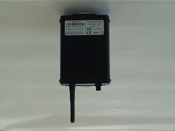
MQXSMLIP
Nov 14, 2001Wireless Modem
Equipment Class
DSS - Part 15 Spread Spectrum Transmitter
MQX550660-001
Oct 29, 2001Wireless STAT TX
Equipment Class
DXX - Part 15 Low Power Communication Device Transmitter
MQX550205-001
Oct 29, 2001Wireless TTX
Equipment Class
DXX - Part 15 Low Power Communication Device Transmitter
MQXD900SS-20-A
Aug 27, 2001DSS - Part 15 Spread Spectrum Transmitter
Equipment Class
DSS - Part 15 Spread Spectrum Transmitter