MQXD900SS-20-A
Adcon Telemetry Inc
Click to zoom
Application Details
- Equipment Class
- DSS - Part 15 Spread Spectrum Transmitter
- Date of Grant
- Aug 27, 2001
- Application Purpose
- Original Equipment
- Date of Application
- Jun 05, 2001
- Frequency Range
- 902.80000000 - 910.15000000
- Company
- Adcon Telemetry Inc
- Country
- United States
Documents & Files
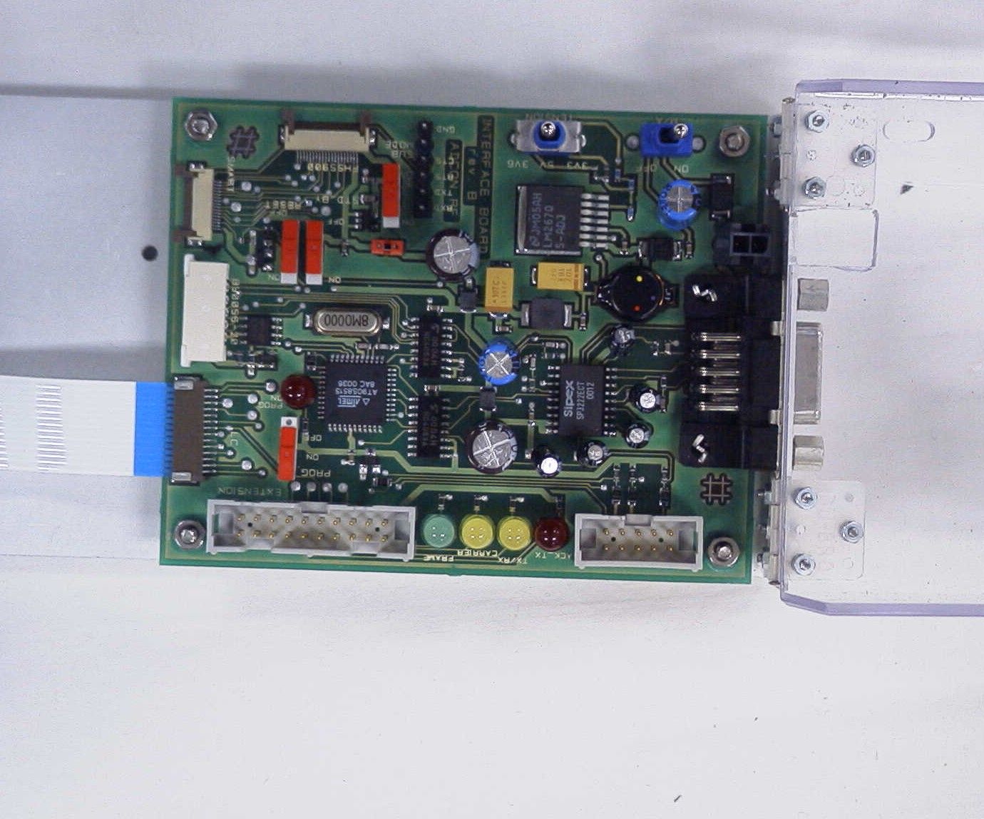
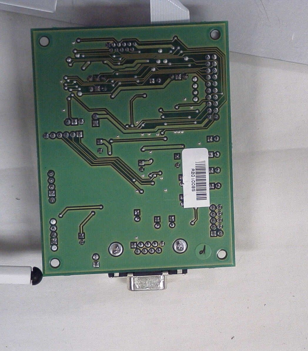
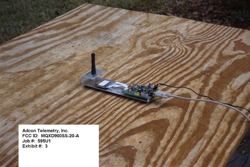
Document Text
Text extracted from the exhibit documents filed with the FCC. Open a document above to read the original.
Users Manual
Technical Manual Technical ManualTechnical Manual Technical Manual EDITION: 0. EDITION: 0.EDITION: 0. EDITION: 0.7 77 7 UPDATED: August 7, 2001 B900ss-20 Radio Modem Card Spread Spectrum (FCC Approved Part 15.247) 2 ADCON AG Adcon Telemetry, Inc. 1001 Yamato Road Suite 305 Boca Raton, Florida 33431 Tel: 561-989-5309 Fax: 561-989-5310 Internet Site http://www.adcon.com E-mail [email protected] The information within this document may be modified without notice. No part of this manual can be duplicated or transferred, electronically or mechanically in any way, without ADCON AG.'s strict and written consent. 3 INDEX Chapter 1. Objective ................................ ................................................................ ................................................................ ................................................................ ................................................................ ................................................................ .............................................. ............................ .............. 5 55 5 Chapter 2. Module introduction ................................ ................................................................ ................................................................ ................................................................ ........................................................... ...................................................... ........................... 6 66 6 2.1. Description................................ ................................................................ ................................................................ ................................................................ ................................................................ ................................................................ ................................................................ ................................................................ ................................ 6 66 6 2.2. Specifications ................................ ................................................................ ................................................................ ................................................................ ................................................................ ................................................................ ............................................................ ........................................................ ............................ 7 77 7 2.2.1. General ............................................................................................................................................. 7 2.2.2. Specifications of the B900ss-20 ...................................................................................................... 7 2.2.3. Schematic ......................................................................................................................................... 9 2.3. Available Configuration ................................ ................................................................ ................................................................ ................................................................ ................................................................ ................................................................ ......................................... .................. ......... 10 1010 10 2.3.1. Software Configuration ................................................................................................................. 10 2.3.2. Hardware Configuration................................................................................................................ 10 Chapter 3. Basic Operation ................................ ................................................................ ................................................................ ................................................................ ................................................................ ................................................................ ................................. .. .11 1111 11 3.1. General................................ ................................................................ ................................................................ ................................................................ ................................................................ ................................................................ ................................................................ ................................................................ .................................... ........ .... 11 1111 11 3.2. "Hayes" Mode ................................ ................................................................ ................................................................ ................................................................ ................................................................ ................................................................ ........................................................ ................................................ ........................ 11 1111 11 3.3. "Point-to-Point" Mode................................ ................................................................ ................................................................ ................................................................ ................................................................ ................................................................ ........................................... ...................... ........... 12 1212 12 3.4. "Network" Mode................................ ................................................................ ................................................................ .............................…
Text truncated - open the document above for the full version.
Cover Letter(s)
Timco Engineering Inc. Adcon Telemetry Inc. 849 NW State Road 45 FCC ID: MQXD900SS-20-A Newberry FL 32669 Corresp. Number : 20075 731Conf. Number: EA101242 Page 1 Enclosed are the replies to your questions some of the answers are based on a conversation of the questions between yourself and Adcon. 1. 1) Verify the requested frequency range should be 902.8-910.15 MHz. The frequency range should 902 – 911 MHz not 902-928. 2. Confidential letter. I have uploaded the confidentiality letter. 3. Submit appropriate fees. I have submitted the payment for this job. The remittance number is 150542 and the authorization number 123285. 4. Indicate compliance with the RF safety requirements. The RF exposure statement is included in the revised user’s manual, which has been uploaded to you. Page number 5 of the revised users manual. 5. Why was the device tested without the enclosure shown in the external photos? The corrected test setup photograph is included as page 5 of this letter and has been uploaded. The one originally sent with this job was the wrong photo. 6. Provide a bandwidth plots on a low, middle and high channel. Bandwidth plots on low middle and high channels are included as pages 7,8, and 9. 7. External photo of the top of the device. The top photograph is included as page 4 and has been uploaded to you. 8. The device has an RS232 port for connecting to a computer. File a composite application for the peripheral portion. Or if it DOC approved, provide the DOC certificate and correct the label to include the DOC label requirements. The D900SS-20-A is an evaluation tool for engineers and is not going to be used in the home or available for sale to the general public for home use, and as such falls under a Class A peripheral. The test report has been updated to reflect this and uploaded to you included in this report as page 6. 9. The manual indicates the use of other antennas that were not tested. Please correct the manual accordingly. This is addressed partially in item 8 above and in revision 0.6 of the users manual has been uploaded to you. See page 6 of this report. 10. How does the device comply with Section 15.203? The antenna is permanently attached and is addressed on page 3 of the test report. 11. The transmitter cannot coordinate its hopping sequence with the hopping sequence of other transmitters, or vice versa, for the purpose of avoiding the simultaneous occupancy of individual hopping frequencies Timco Engineering Inc. Adcon Telemetry Inc. 849 NW State Road 45 FCC ID: MQXD900SS-20-A Newberry FL 32669 Corresp. Number : 20075 731Conf. Number: EA101242 Page 2 by multiple transmitters. Provide a description on how the device complies with this rule. Once the radios have been configured and completed the “acquisition procedure”, the radios in the network operate completely independently of any other radios in the local area. Eight different hopping tables are available for each network, and this provides an additional method to minimize collisions between networks. 12. The system shall hop to channel frequencies that are selected at the system hopping rate from a pseudorandomly ordered list of hopping frequencies. Indicate how the pseudorandom hopping sequence is derived. The 8 pseudorandom hopping tables are burned into the EEPROM memory, and do not change. All 8 tables have the following characteristics: they use each channel only once per 50 hops, and they move randomly both in direction and in number of channels hopped. They were derived with the following procedure: The first three tables were created with an algorithm “maximal-length pseudo- random linear feedback shift register (LFSR)” based on maximum lengths of 6,7,8 bits, with rejection of frequencies already used. The other tables (tables 4-8) were created with an algorithm based on the RANDOM () function, with rejection of frequencies already used. 13. Each frequency must be used equally on the average by each transmitter. Except for voice systems, each new transmission must start at a different point in the sequence so that on average the full sequence is used. Therefore, Describe where the next transmission starts when all frequencies are not used for a previous message. This is required because some transmissions may need only a few frequency hops to be completed. i.e. If the transmission started on the same frequency each time, this frequency would be used more than the others if many short transmissions were sent. The next transmission starts with the next channel in the hopping table sequence. For example, if a short transmission starts with the first channel in the hopping table and needs only 8 hops to complete the transmission, the next transmission will start with the ninth channel in the hopping table sequence. 14. Section 15.247(a) 1 indicates that the system receivers shall have input bandwidths that match the hopping channel bandwidths of their corresponding transmitters and shall shift frequencies in synchronization with the transmitted signals. Please explain how the device complies with this rule when a packet is repeated or when multiple packets are sent. What is the receiver input bandwidth? How does the receiver shift frequencies and determine which frequency to shift to in order to synchronize with this transmitter? The receiver uses a VCO to rapidly shift frequencies in synchronization with the transmitted signals, based on the hopping table that was chosen during the acquisition procedure. Timco Engineering Inc. Adcon Telemetry Inc. 849 NW State Road 45 FCC ID: MQXD900SS-20-A Newberry FL 32669 Corresp. Number : 20075 731Conf. Number: EA101242 Page 3 When a packet is repeated, it is transmitted on the next hopping channel, which is a different frequency. The receiver input bandwidth is limited by the filters on the receiver, which have a pass band of +/- 50kHz at 3dB. The adjacent channel rejection is 20dB. The receiver shifts frequencies with the following procedure: After changing to a new hop…
Text truncated - open the document above for the full version.
Cover Letter(s)
Timco Engineering Inc.Adcon Telemetry Inc. 849 NW State Road 45FCC ID: MQXD900SS-20-A Newberry FL 32669Corresp. Number : 20075 731Conf. Number: EA101242 Enclosed are the replies to your questions. 1. Confidential letter. I have uploaded the confidentiality letter. 2. Provide a bandwidth plots on a low, middle and high channel. Bandwidth plots on low middle and high channels are included as pages 2, 3, & 4. 3. Users Manual I have uploaded the revised users manual. Timco Engineering Inc.Adcon Telemetry Inc. 849 NW State Road 45FCC ID: MQXD900SS-20-A Newberry FL 32669Corresp. Number : 20075 731Conf. Number: EA101242 Timco Engineering Inc.Adcon Telemetry Inc. 849 NW State Road 45FCC ID: MQXD900SS-20-A Newberry FL 32669Corresp. Number : 20075 731Conf. Number: EA101242 Timco Engineering Inc.Adcon Telemetry Inc. 849 NW State Road 45FCC ID: MQXD900SS-20-A Newberry FL 32669Corresp. Number : 20075 731Conf. Number: EA101242
Test Report
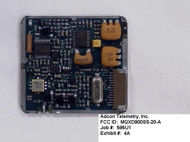
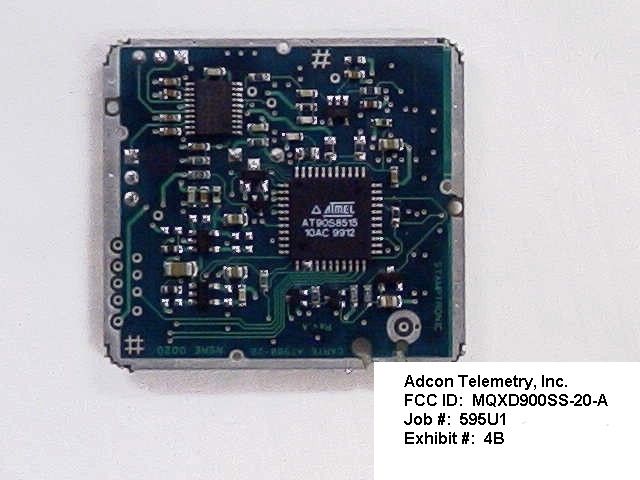
APPLICANT: ADCON TELEMETRY, INC. FCC ID: MQXD900SS-20-A TABLE OF CONTENTS TEST REPORT CONTAINING: PAGE 1.............TEST PROCEDURES PAGE 2.............TEST PROCEDURES CONTD. & EQUIPMENT LIST PAGE 3.............GENERAL INFORMATION & PRODUCT DESCRIPTION PAGE 4.............POWER LINE CONDUCTED EMISSIONS TEST DATA PAGE 5.............POWER OUTPUT PAGE 6.............SPURIOUS EMISSIONS AT ANTENNA TERMINALS PAGE 7.............RADIATION INTERFERNECE TEST DATA PAGE 8.............METHOD OF MEASURING RADIATION INTERFERENCE EXHIBIT ATTACHMENTS: EXHIBIT 1...........FCC ID LABEL SAMPLE EXHIBIT 2...........SKETCH OF FCC ID LABEL LOCATION EXHIBIT 3...........TEST SETUP PHOTOGRAPH EXHIBIT 4A..........INTERNAL COMPONENT VIEW - RF BOARD EXHIBIT 4B..........INTERNAL SOLDER SIDE - RF BOARD EXHIBIT 4C-4D.......INTERNAL PRINTED CIRCUIT BOARD EXHIBIT 5...........BLOCK DIAGRAM EXHIBIT 6A-6I.......SCHEMATICS EXHIBIT 7...........INSTRUCTION MANUAL EXHIBIT 8A-8B.......PSEUDORANDUM FREQUENCY HOPPING DESCRIPTION EXHIBIT 9A-9B.......POWER LINE CONDUCTED PLOTS EXHIBIT 10..........FREQUENCY RANGE OF HOPS EXHIBIT 11..........CHANNEL SEPARATION OF HOPS EXHIBIT 12..........DWELL TIME OF HOPS EXHIBIT 13..........20dB BANDWIDTH PLOT APPLICANT: ADCON TELEMETRY, INC. FCC ID: MQXD900SS-20-A REPORT NO.: T:\CUS\A\ADCON\595U1\595U1TestReport.doc PAGE #: TABLE OF CONTENTS TEST PROCEDURE GENERAL: This report shall NOT be reproduced except in full without the written approval of TIMCO ENGINEERING, INC. The UUT was transmit- ting a test signal during the testing. 15.247(a)(1) CARRIER FREQUENCY SEPARATION & NUMBER OF CHANNELS: A near field probe was used to sense the signal of the UUT. The UUT was made to hop its full range. The spectrum analyzer was set to view the frequency range from 902 to 910MHz and placed in the memory mode. A plot (Exhibit #9) was then made of the display showing the number of channels, 50 and the separation of the channels, 152 kHz. 15.247(a)(1)(i) CARRIER FREQUENCY DWELL TIME: A near field probe was used to sense the signal of the UUT. The UUT was made to hop its full range. The spectrum analyzer was set to view the frequency range from 902 to 928 MHz and the center of the HOPPING RANGE was centered on the Spectrum Analyzer. The SPAN was then set to ZERO(0) and the SWEEP TIME was set to 20 seconds. Then by analyzing the plot of the total ON TIME of the UUT during the 20 seconds it was determined the dwell time on any frequency was less than 0.4 seconds, 23.70 mseconds. See exhibit #11. 15.247(b)(2) POWER OUTPUT: The RF power output was measured at the antenna feed point by removing the permanent antenna and connecting the UUT to a peak power meter, HP Model No. 8900C. 15.247(c) ANTENNA CONDUCTED EMISSIONS: The RBW=100kHz, VBW =1.0MHz up to 1000MHz and RBW=1.0MHz & VBW=3.0MHz above 1.0GHz. The spectrum was scanned from 30MHz to the 10th Harmonic of the fundamental. RADIATION INTERFERENCE: The test procedure used was ANSI STANDARD C63.4-1992 using a HEWLETT PACKARD spectrum analyzer with a prese- lector. The analyzer was calibrated in dB above a microvolt at the output of the antenna. The resolution bandwidth was 100kHz and the video bandwidth was 300 kHz up to 1.0GHz and 1.0MHz with a video BW of 3.0MHz above 1.0 GHz. The ambient temperature of the UUT was 72.2°F with a humidity of 54.2%. The hopping was stopped at the low end, middle and high end of the band in order to test the radiated emis- sions. POWER LINE CONDUCTED INTERFERENCE: The procedure used was ANSI STAN- DARD C63.4-1992 using a 50uH LISN. Both lines were observed. The bandwidth of the spectrum analyzer was 10kHz with an appro- priate sweep speed. The ambient temperature of the UUT was 74°F with a humidity of 54%. APPLICANT: ADCON TELEMETRY, INC. FCC ID: MQXD900SS-20-A REPORT #: T:\CUS\A\ADCON\595U1\595U1TestReport.doc PAGE #: 1 TEST PROCEDURES CONTINUED FORMULA OF CONVERSION FACTORS: The Field Strength at 3m was estab- lished by adding the meter reading of the spectrum analyzer (which is set to read in units of dBuV) to the antenna correction factor sup- plied by the antenna manufacturer. The antenna correction factors are stated in terms of dB. The gain of the Preselector was accounted for in the Spectrum Analyzer Meter Reading. Example: Freq (MHz) METER READING + ACF = FS 33 20 dBuV + 10.36 dB = 30.36 dBuV/m @ 3m TEST EQUIPMENT LIST 1._X_Spectrum Analyzer: HP 8566B-Opt 462, S/N 3138A07786, w/ preselector HP 85685A, S/N 3221A01400, Quasi-Peak Adapter HP 8565OA, S/N 3303A01690 & Preamplifier HP 8449B-OPT H02, S/N 3008A00372 Cal. 10/17/00 2._X_Biconnical Antenna: Eaton Model 94455-1, S/N 1057 3.___Biconnical Antenna: Electro-Metrics Model BIA-25, S/N 1171 4._X_Log-Periodic Antenna: Electro-Metrics Model EM-6950, S/N 632 5.___Log-Periodic Antenna: Electro-Metrics Model LPA-30, S/N 409 6._X__Double-Ridged Horn Antenna: Electro-Metrics Model RGA-180, 1-18 GHz, S/N 2319 7.___18-26.3GHz Systron Donner Standard Gain Horn #DBE-520-20 8.___Horn 40-60GHz: ATM Part #19-443-6R 9.___Line Impedance Stabilization Network: Electro-Metrics Model ANS-25/2, S/N 2604 Cal. 2/9/00 10.___Temperature Chamber: Tenney Engineering Model TTRC, S/N 11717-7 11.___Frequency Counter: HP Model 5385A, S/N 3242A07460 Cal 10/6/00 12.___Peak Power Meter: HP Model 8900C, S/N 2131A00545 13._X_Open Area Test Site #1-3meters Cal. 12/22/99 14.___Signal Generator: HP 8640B, S/N 2308A21464 Cal. 9/23/00 15.___Signal Generator: HP 8614A, S/N 2015A07428 16.___Passive Loop Antenna: EMCO Model 6512, 9KHz to 30MHz, S/N 9706-1211 Cal. 6/10/00 17.___Dipole Antenna Kit: Electro-Metrics Model TDA-30/1-4, S/N 153 Cal. 11/24/00 18.___AC Voltmeter: HP Model 400FL, S/N 2213A14499 Cal. 9/21/00 19.___Digital Multimeter: Fluke Model 8012A, S/N 4810047 Cal 9/21/00 20.___Digital Multimeter: Fluke Model 77, S/N 43850817 Cal 9/21/00 21.___Oscilloscope: Tektronix Model 2230, S/N 300572 Cal 9/23/00 APPLICANT: ADCON TELEMETRY, INC. FCC ID: MQXD900SS-20-A REPORT #: T:\CUS\A\ADCON\595U1\595U1TestReport.doc PAGE #: …
Text truncated - open the document above for the full version.
Contact Information
Applicant
Lix Paulian(R&D Systems Designer)
Technical Contact
Timco Engineering, Inc.Mario R de Aranzeta
[email protected]352-472-5500
849 N.W. State Road 45 · Newberry, Florida · United States
Non-Technical Contact
Timco Engineering, Inc.Sharon A Hoffman
[email protected]352-472-500
Test Firm
Timco Engineering, Inc.Sid Sanders
Technical Specifications
| # | Rule Parts | Frequency Range | Power Output |
|---|---|---|---|
| 1 | 15C | 902.8 MHz - 910.15 MHz | 20.00 mW |
Other Applications from Adcon Telemetry Inc
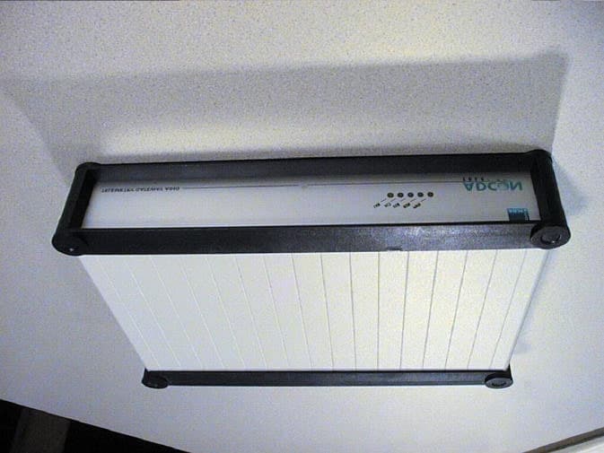
MQXA840
Jan 16, 2002Telemetry Gateway
Equipment Class
JBP - Part 15 Class B Computing Device Peripheral
MQXB900SS-500
Jan 01, 2002FM Radio Transceiver Module
Equipment Class
DSS - Part 15 Spread Spectrum Transmitter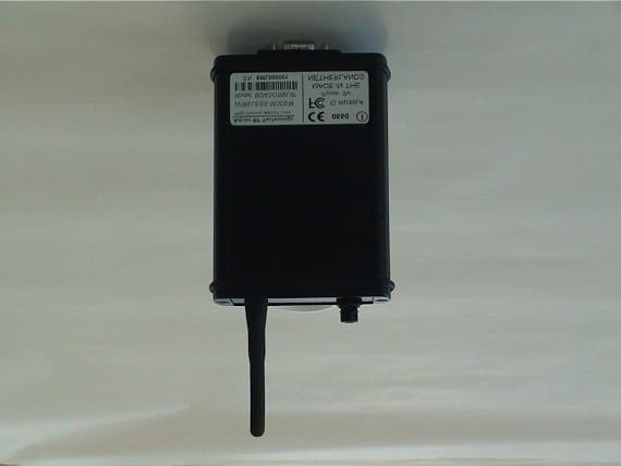
MQXSMLIP
Nov 14, 2001Wireless Modem
Equipment Class
DSS - Part 15 Spread Spectrum Transmitter
MQX550660-001
Oct 29, 2001Wireless STAT TX
Equipment Class
DXX - Part 15 Low Power Communication Device Transmitter
MQX550205-001
Oct 29, 2001Wireless TTX
Equipment Class
DXX - Part 15 Low Power Communication Device Transmitter