MSAB15BFLCD Monitor
Hansol LCD Inc.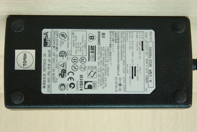
Click to zoom
Application Details
- Equipment Class
- JBP - Part 15 Class B Computing Device Peripheral
- Date of Grant
- Jul 05, 2001
- Application Purpose
- Original Equipment
- Date of Application
- Jul 05, 2001
- Equipment Note
- LCD Monitor
- Company
- Hansol LCD Inc.
- Country
- South Korea
Documents & Files
Document Text
Text extracted from the exhibit documents filed with the FCC. Open a document above to read the original.
Users Manual
Parts 3 Connection to Computer 4 How to Adjust Monitor Angle 5 Installing Monitor Driver 6 Name and Function of Front 8 Power Management Feature 10 Adjusting OSD 11 Standard Signal Table 17 Specification 18 Troubleshooting 19 Warning 21 Table of Contents INFORMATION TO USER: This equipment has been tested and found to comply with the limits of a Class B digital device, pursuant to Part 15 of the FCC Rules. These limits are designed to provide reasonable protection against harmful interference in a residential installation. This equipment generates, uses and can radiate radio frequency energy and, if not installed and used in accordance with the instructions, may cause harmful interference to radio communications. However, there is no guarantee that interference will not occur in a particular installation; if this equipment does cause harmful interference to radio or television reception, which can be determined by turning the equipment off and on, the user is encouraged to try to correct the interference by one or more of the following measures: 1. Reorient / Relocate the receiving antenna. 2. Increase the separation between the equipment and receiver. 3. Connect the equipment into an outlet on a circuit difference from that to which the receiver is connected. 4. Consult the dealer or an experienced radio/TV technician for help. • Shielded interface cable has to be used to ensure product compliance. CAUTION: Changes or modifications not expressly approved by the manufacturer responsible for compliance could void the user’s authority to operate the equipment 3 2 Parts LCD Monitor Place the monitor to face the user and then adjust the monitor angle.Take a break (for about 10 minutes) at every hour during the work with monitor. Refer to the following figure to take the correct posture. about 50cm Look down the monitor below the horizon. Relax shoulders and arms, and sit back on the chair. Adjust the monitor to prevent reflection. Adjust the monitor stand to acquire required angle. Keep feet flat on the ground. Maintain the arms horizontally and place hands softly on the keyboard. Good Posture Guide 12V-DC Adapter User's Manual / Warranty Card Signal Cable AC Power Cable Installation Disk Installation Diskette 5 How to Adjust Monitor Angle How to Default Stand 4 Connection to Computer Basic Connection 1. Use 220 V or 110 V. (Free Voltage)2. Connect monitor and computer via computer cable (See figure ) 3. Switch on power to monitor and computer.4. Installation is finished. 12V DC connection terminal Computer cable For PC For Macintosh Use adapter. Adapter for Macintosh (Optional)Refer to the table on the rear side ofthe optional Macintosh adapter andadjust DIP switch by the resolution ofthe monitor. 7 6 Click 'Finish'. Click 'Next>'. Click 'Advanced..'. Click 'Next>'. Click 'Monitor'. Click 'Display a list of all...'.Click 'Next>'. Click 'Have Disk..'. Select the driver and click 'OK'. Click 'Next>'. 3. Select Exit if the monitor model is changed, and then reboot Windows. Installing Monitor Driver 1. Insert the Diskette in the Floppy driver. 2. Double-click Install.exe in the Floppy driver folder using search function. 3. Select the model and click "OK".4. Select inf file of the model in Floppy driver, and then click "OK" button.5. Click "Exit" to close the installation. Automatic Installation Manual Installation 1. Insert the Diskette in the Floppy driver.2. Click 'My Computer' and follow the procedure below. Click 'Control Panel'. Click 'Display'. Click 'Settings'. Run (Click) Install at Floppy driver and select the product model to set theoptimum display in Window 95, 98 or 2000. Use the Driver Floppy provided. 9 8 Power Switch Power switch is located in the lower center of the monitor stand.You can push the switch to turn on/off the power. Power Saving LED If the green LED around the power switch turns into blinking amber, it indicates the monitor is in power saving mode. On Screen Display (OSD) Function Button OSD buttons on the front of the monitor perform the following functions. MENU : Press this button to display menus.SELECT/ AUTO : Press this button, when OSD is not displayed, to perform automatic setting. When OSD is displayed, You can select the Item. POWER : Power switch. : By pressing this button when OSD is displayed, You can move cursor into the menus which You want.After press the select button, You can change the gauge level and items. Functions Name and Function of Front Front panel SELECT/ AUTO KEY MENU KEY + KEY - KEY POWER KEY 11 Horizontal Position Adjusting OSD Brightness Contrast MENU 1. Press the Menu button.2. Use to move Brightness ICON. 3. Use SELECT button to select it.4. Use to adjust the brightness. SELECT MENU SELECT MENU SELECT 1. Press the Menu button.2. Use to move Contrast ICON. 3. Use SELECT button to select it.4. Use to adjust the contrast. 1. Press the Menu button.2. Use to move H-Position ICON. 3. Use SELECT button to select it.4. Use to adjust display left or right. 10 No image is displayed with LED blinking. Monitor is in power saving mode.Use mouse or keyboard to release power saving mode. No image is displayed without LED on. Power cable plug must be pulled out.Check the power plugs on monitor and on the wall. "Out of range" displayed on the screen. This message is displayed when the signal from video card exceeds themaximum frequency of the monitor. Readjust resolution and frequency inaccordance with the monitor capacity. (Refer to Standard Signal Table) Power Management Feature When not in use for a long period of time, the monitor automatically reduces its power consumption, meeting power savingstandards of EPA and NUTEK. The monitor is equipped with a power saving circuit that conforms to the world-standard Display Power Manager Signalling(DPMS) mode of Video Electronics Standard Association (VESA).The power management feature requires that the video card of thecomputer should support DPMS function. Status Color of LED Power Consumption Normal…
Text truncated - open the document above for the full version.
Block Diagram
ANALOG RGB (PC) BlockDiagram Block-Diagram(A/D)
External Photos
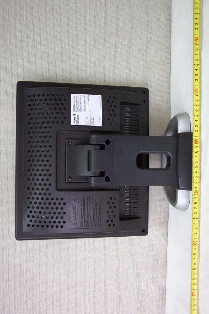
EUT External Photos Certitek Standards Laboratory Co., Ltd. VCCI Registration No. R-948, C-986 FCC Registration No. 93250 Page 1 of 6 www.certitek.com Certitek Standards Laboratory Co., Ltd. 386-1, Ho-Dong, Yongin-City, Kyunggi-Do, KOREA 449-100 EUT External Photos Front EUT External Photos Certitek Standards Laboratory Co., Ltd. VCCI Registration No. R-948, C-986 FCC Registration No. 93250 Page 2 of 6 www.certitek.com Certitek Standards Laboratory Co., Ltd. 386-1, Ho-Dong, Yongin-City, Kyunggi-Do, KOREA 449-100 Rear EUT External Photos Certitek Standards Laboratory Co., Ltd. VCCI Registration No. R-948, C-986 FCC Registration No. 93250 Page 5 of 6 www.certitek.com Certitek Standards Laboratory Co., Ltd. 386-1, Ho-Dong, Yongin-City, Kyunggi-Do, KOREA 449-100 Adaptor (Front) EUT External Photos Certitek Standards Laboratory Co., Ltd. VCCI Registration No. R-948, C-986 FCC Registration No. 93250 Page 6 of 6 www.certitek.com Certitek Standards Laboratory Co., Ltd. 386-1, Ho-Dong, Yongin-City, Kyunggi-Do, KOREA 449-100 Adaptor (Rear)
ID Label/Location Info
EUT External Photos Certitek Standards Laboratory Co., Ltd. VCCI Registration No. R-948, C-986 FCC Registration No. 93250 Page 3 of 6 www.certitek.com Certitek Standards Laboratory Co., Ltd. 386-1, Ho-Dong, Yongin-City, Kyunggi-Do, KOREA 449-100 Label (Format) EUT External Photos Certitek Standards Laboratory Co., Ltd. VCCI Registration No. R-948, C-986 FCC Registration No. 93250 Page 4 of 6 www.certitek.com Certitek Standards Laboratory Co., Ltd. 386-1, Ho-Dong, Yongin-City, Kyunggi-Do, KOREA 449-100 Label (Location) Location : Rear Side of EUT
Internal Photos
EUT Internal Photos Certitek Standards Laboratory Co., Ltd. VCCI Registration No. R-948, C-986 FCC Registration No. 93250 Page 1 of 10 www.certitek.com Certitek Standards Laboratory Co., Ltd. 386-1, Ho-Dong, Yongin-City, Kyunggi-Do, KOREA 449-100 EUT Internal Photos EUT (Inside) EUT Internal Photos Certitek Standards Laboratory Co., Ltd. VCCI Registration No. R-948, C-986 FCC Registration No. 93250 Page 2 of 10 www.certitek.com Certitek Standards Laboratory Co., Ltd. 386-1, Ho-Dong, Yongin-City, Kyunggi-Do, KOREA 449-100 Taping EUT Internal Photos Certitek Standards Laboratory Co., Ltd. VCCI Registration No. R-948, C-986 FCC Registration No. 93250 Page 3 of 10 www.certitek.com Certitek Standards Laboratory Co., Ltd. 386-1, Ho-Dong, Yongin-City, Kyunggi-Do, KOREA 449-100 Main Board (Front) EUT Internal Photos Certitek Standards Laboratory Co., Ltd. VCCI Registration No. R-948, C-986 FCC Registration No. 93250 Page 4 of 10 www.certitek.com Certitek Standards Laboratory Co., Ltd. 386-1, Ho-Dong, Yongin-City, Kyunggi-Do, KOREA 449-100 Main Board (Rear) EUT Internal Photos Certitek Standards Laboratory Co., Ltd. VCCI Registration No. R-948, C-986 FCC Registration No. 93250 Page 5 of 10 www.certitek.com Certitek Standards Laboratory Co., Ltd. 386-1, Ho-Dong, Yongin-City, Kyunggi-Do, KOREA 449-100 LCD (Front) EUT Internal Photos Certitek Standards Laboratory Co., Ltd. VCCI Registration No. R-948, C-986 FCC Registration No. 93250 Page 6 of 10 www.certitek.com Certitek Standards Laboratory Co., Ltd. 386-1, Ho-Dong, Yongin-City, Kyunggi-Do, KOREA 449-100 LCD (Rear) EUT Internal Photos Certitek Standards Laboratory Co., Ltd. VCCI Registration No. R-948, C-986 FCC Registration No. 93250 Page 7 of 10 www.certitek.com Certitek Standards Laboratory Co., Ltd. 386-1, Ho-Dong, Yongin-City, Kyunggi-Do, KOREA 449-100 DC-DC Converter (Front) EUT Internal Photos Certitek Standards Laboratory Co., Ltd. VCCI Registration No. R-948, C-986 FCC Registration No. 93250 Page 8 of 10 www.certitek.com Certitek Standards Laboratory Co., Ltd. 386-1, Ho-Dong, Yongin-City, Kyunggi-Do, KOREA 449-100 DC-DC Converter (Rear) EUT Internal Photos Certitek Standards Laboratory Co., Ltd. VCCI Registration No. R-948, C-986 FCC Registration No. 93250 Page 9 of 10 www.certitek.com Certitek Standards Laboratory Co., Ltd. 386-1, Ho-Dong, Yongin-City, Kyunggi-Do, KOREA 449-100 Adaptor Main Board (Front) EUT Internal Photos Certitek Standards Laboratory Co., Ltd. VCCI Registration No. R-948, C-986 FCC Registration No. 93250 Page 10 of 10 www.certitek.com Certitek Standards Laboratory Co., Ltd. 386-1, Ho-Dong, Yongin-City, Kyunggi-Do, KOREA 449-100 Adaptor Main Board (Rear)
Test Report
Test Report No. CTK01 – F097 Certitek Standards Laboratory Co., Ltd. VCCI Registration No. R-948, C-986 FCC Registration No. 93250 Issue: 2001-07-06 Page 1 of 10 www.certitek.com Certitek Standards Laboratory Co., Ltd. 386-1, Ho-Dong, Yongin-City, Kyunggi-Do, KOREA 449-100 Model: B15BF FCC ID MSAB15BF Product type LCD Monitor Serial No. - Applicant Hansol Electronics Inc. Address 27-29, Hanchon-Ri, Ducksan-Myun, Jinchon-Gun, Chungbuk, 365-840, Korea. Manufacturer Hansol Electronics Inc. Address 27-29, Hanchon-Ri, Ducksan-Myun, Jinchon-Gun, Chungbuk, 365-840, Korea. Test specification (Standard) : FCC Part15 Subpart B Class B Test Result : In compliance Tested by (Test engineer) 2001-07-06 Young Joon, Park Date Name Signature Reviewed by (EMC Technical Manager) 2001-07-06 James, Hong Date Name Signature Definition : Applicable, : Not Applicable, N/A : Not Applicable, - : Not Applicable The test result only responds to the tested sample. No single part of this document may be reproduced without permission from Certitek Standards Laboratory Co., Ltd. Tel: +82-31-339-9970, Fax: +82-31-339-9972 E E E M M M C C C - - - T T T e e e s s s t t t R R R e e e p p p o o o r r r t t t ( ( ( F F F C C C C C C ) ) ) Test Report No. CTK01 – F097 Certitek Standards Laboratory Co., Ltd. VCCI Registration No. R-948, C-986 FCC Registration No. 93250 Issue: 2001-07-06 Page 2 of 10 www.certitek.com Certitek Standards Laboratory Co., Ltd. 386-1, Ho-Dong, Yongin-City, Kyunggi-Do, KOREA 449-100 Table of contents 1. EUT description................................................................................................................................3 Introduction..............................................................................................................................................................3 Identification............................................................................................................................................................3 Electrical rating.......................................................................................................................................................3 2. Test Set-up............................................................................................................................................4 Test Mode..................................................................................................................................................................4 Cable configuration................................................................................................................................................4 Cable description....................................................................................................................................................5 Auxiliary equipment..............................................................................................................................................5 Test software.............................................................................................................................................................5 Measurement Procedures.....................................................................................................................................6 3. Test Result............................................................................................................................................7 Test summary...........................................................................................................................................................7 Radiated emission...................................................................................................................................................8 Conducted emission...............................................................................................................................................9 Test Report No. CTK01 – F097 Certitek Standards Laboratory Co., Ltd. VCCI Registration No. R-948, C-986 FCC Registration No. 93250 Issue: 2001-07-06 Page 3 of 10 www.certitek.com Certitek Standards Laboratory Co., Ltd. 386-1, Ho-Dong, Yongin-City, Kyunggi-Do, KOREA 449-100 1. EUT description Introduction B15BF is a LCD type 15" color monitor. Identification Receipt date : 2001-06-04 Model : B15BF Manufacturer : Hansol Electronics Inc. Address : 27-29, Hanchon-Ri, Ducksan-Myun, Jinchon-Gun, Chungbuk, 365-840, Korea. Contact person : Sun-Pil, Yang Telephone : +82 - 43 - 530 - 8503 Serial No : - EUT Size : 358mm(W) x 128mm(D) x 346mm(H) Peripheral Device Ports Port name Description VIDEO Connect to PC Video port DC IN Connect to adaptor Electrical rating Input : 12Vdc, 3A Output : - Test Report No. CTK01 – F097 Certitek Standards Laboratory Co., Ltd. VCCI Registration No. R-948, C-986 FCC Registration No. 93250 Issue: 2001-07-06 Page 4 of 10 www.certitek.com Certitek Standards Laboratory Co., Ltd. 386-1, Ho-Dong, Yongin-City, Kyunggi-Do, KOREA 449-100 2. Test Set-up Test Mode - Normal operation mode : 1024 x 768 @ 75Hz 1. Emission : Scrolling 'H' character. Cable configuration EUT LCD Monitor (B15BF) PC A E C AC Power 1 2 3 MOUSE (PS/2) PRINTER AC Power GAME PAD HEAD SET KEYBOARD MOUSE (SERIAL) 4 7 8 10 9 11 12 AC Power 5 6 D G H K B MOUSE (USB) Adaptor 13 I J F Test Report No. CTK01 – F097 Certitek Standards Laboratory Co., Ltd. VCCI Registration No. R-948, C-986 FCC Registration No. 93250 Issue: 2001-07-06 Page 5 of 10 www.certitek.com Certitek Standards Laboratory Co., Ltd. 386-1, Ho-Dong, Yongin-City, Kyunggi-Do, KOREA 449-100 Cable description Cable name Type Length (m) Remark 1 Video Cable Shielded 1.6 Ferrite core 2 EUT Power Cable Unshielded 2.0 - 3 PC Power Cable Unshielded 2.0 - 4 Parallel Cable Shielded 2.0 - 5 Printer Power Cable Unshielded 2.0 - 6 Game Pad Cable Unshielded 2.0 - 7 Head Set Cable Unshielded 2.0 - 8 Line in Cable Unshielded 2.0 - 9 Keyboard Cable Unshielded 2…
Text truncated - open the document above for the full version.
Test Setup Photos
TEST Setup Photos Certitek Standards Laboratory Co., Ltd. VCCI Registration No. R-948, C-986 FCC Registration No. 93250 Page 1 of 4 www.certitek.com Certitek Standards Laboratory Co., Ltd. 386-1, Ho-Dong, Yongin-City, Kyunggi-Do, KOREA 449-100 TEST Setup Photos Radiated Emission (Front) TEST Setup Photos Certitek Standards Laboratory Co., Ltd. VCCI Registration No. R-948, C-986 FCC Registration No. 93250 Page 2 of 4 www.certitek.com Certitek Standards Laboratory Co., Ltd. 386-1, Ho-Dong, Yongin-City, Kyunggi-Do, KOREA 449-100 Radiated Emission (Rear) TEST Setup Photos Certitek Standards Laboratory Co., Ltd. VCCI Registration No. R-948, C-986 FCC Registration No. 93250 Page 3 of 4 www.certitek.com Certitek Standards Laboratory Co., Ltd. 386-1, Ho-Dong, Yongin-City, Kyunggi-Do, KOREA 449-100 Conducted Emission (Front) TEST Setup Photos Certitek Standards Laboratory Co., Ltd. VCCI Registration No. R-948, C-986 FCC Registration No. 93250 Page 4 of 4 www.certitek.com Certitek Standards Laboratory Co., Ltd. 386-1, Ho-Dong, Yongin-City, Kyunggi-Do, KOREA 449-100 Conducted Emission (Rear)
Contact Information
Applicant
Sun-pil Yang(Assistant Manager)
Test Firm
CTK Co., Ltd.Jang-Hee Hong
Technical Specifications
| # | Rule Parts | Frequency Range | Power Output |
|---|---|---|---|
| 1 | 15B | - | - |
Other Applications from Hansol LCD Inc.
MSAB15AC
May 12, 200415" CCTV MONITOR
Equipment Class
JBP - Part 15 Class B Computing Device Peripheral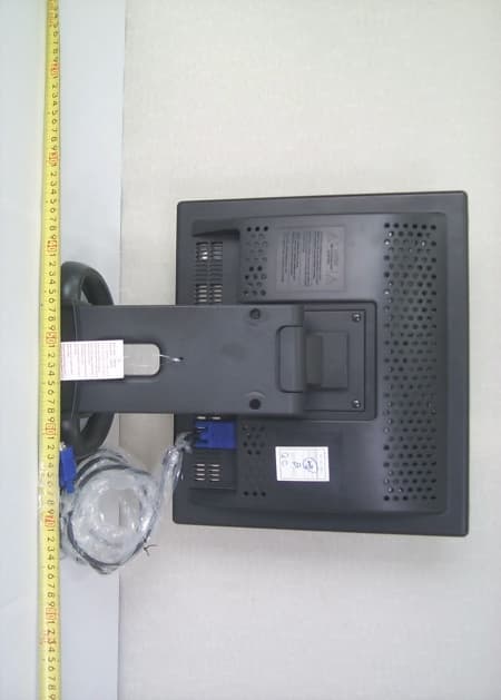
MSAB19AC
Oct 23, 200319" CCTV MONITOR
Equipment Class
JBP - Part 15 Class B Computing Device Peripheral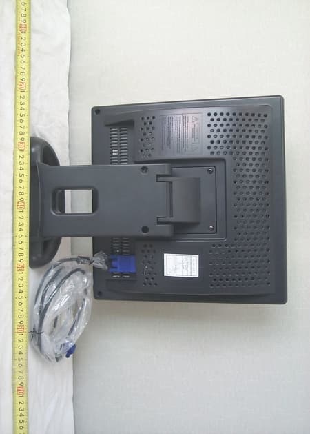
MSAB17AC
Oct 23, 200317" CCTV MONITOR
Equipment Class
JBP - Part 15 Class B Computing Device Peripheral
MSAD17DL-1
Aug 26, 200317" CRT MONITER
Equipment Class
JBP - Part 15 Class B Computing Device Peripheral
MSAB17DF-1
Aug 20, 200317" LCD MONITER
Equipment Class
JBP - Part 15 Class B Computing Device Peripheral