MTF09000Cellular Alarm Transmission System
Telular Corporation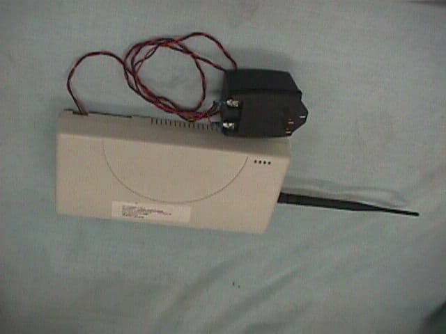
Click to zoom
Application Details
- Equipment Class
- TNB - Licensed Non-Broadcast Station Transmitter
- Date of Grant
- Jan 04, 2001
- Application Purpose
- Original Equipment
- Date of Application
- Jan 04, 2001
- Equipment Note
- Cellular Alarm Transmission System
- Frequency Range
- 824.00000000 - 849.00000000
- Company
- Telular Corporation
- Country
- United States
Documents & Files
Document Text
Text extracted from the exhibit documents filed with the FCC. Open a document above to read the original.
Users Manual
56019201© 2000 Telular Corporation TELGUARD ® Cellular Alarm Transmission System Using Microburst ™ Control Channel Technology MODEL T100C001 U L R INSTALLATION AND OPERATING INSTRUCTIONS COMPANY CONFIDENTIAL For use by TELGUARD ® customers only. Distribution to others strictly prohibited. December 21, 2000 TELGUARD ® is a registered trademark of Telular Corporation. Products are protected under one or more of the following U.S. patents: 4,658,096 4,737,975 4,775,997 4,868,519 4,922,517 © 2000 Telular Corporation C O R P O R A T I O N ® Corporate Headquarters 647 North Lakeview Parkway Vernon Hills, Illinois 60061 847-247-9400 Fax: 847-247-0021 T E L U L A R 56019201 Pag e © 2000 Telular Corporation i FOREWORD Many customers purchase the Telguard because they prefer its price and features, but do not intend to use it in an application that requires UL Grade A Burglary or Fire Listings. If such UL Listings are not required, it is possible to use model T100C001 that is UL Listed for Supplemental Use only. This means that the T100C001 will not enhance the grade of service. Also, the T100C001 is not to be used as a main or secondary line for a fire or burglar alarm system. NOTICES A BOUT T HIS M ANUAL This manual assumes that you have basic security system installation skills such as measuring voltages, stripping w ire, properly connecting w ires together, connecting w ires to terminals, and checking phone lines. It also assumes that you have a familiarity with the proper installation and programming tasks related to various Control/Communicator panels. The material and instructions covered in this manual have been carefully checked for accuracy and are presumed to be reliable. However, Telular assumes no responsibility for inaccuracies and reserves the right to modify and revise this manual without notice. It is our goal at Telular to always supply accurate and reliable documentation. If a discrepancy is found in this documentation, please mail or fax a photocopy of the corrected material to: Telular Security Products Technical Services Department 420 Thornton Road, Suite 109 Lithia Springs, GA 30122 Fax: 678-945-1651 © 2000 Telular Corporation. Lithia Springs, GA U.S.A. All rights reserved. FCC Notices E XPOSURE TO R ADIO F REQUENCY E NERGY In 1991, the Institute of Electrical and Electronics Engineers (IEEE), and in 1992, the American National Standards Institute (ANSI), updated the 1982 ANSI Standard for safety levels with respect to human exposure to RF energy. Over 120 scientists, engineers and physicians from universities, government health agencies and industry, after reviewing the available body of research, developed this updated Standard. In March, 1993, the U.S. Federal Communications Commission (FCC) proposed the adoption of this updated Standard. The design of your Telular Telguard DataBurst complies with this updated Standard. Of course, if you want to limit RF exposure even further than the updated ANSI Standard, you may choose to install the unit in a manner that locates its antenna at an even greater distance from the general public than is recommended as a mi ni mum b y the s ta nd a r d . To insure compliance with the standard, when selecting a mounting location for your Telguard DataBurst do not mount it (or its associated antenna) in an area where the general public could reasonably be within 8 inches (20 centimeters) of the antenna. 56019201 Pag e © 2000 Telular Corporation ii E FFICIENT O PERAT ION Do not operate your Telular product when holding the antenna. Be sure to mount the unit such that its antenna is a minimum of eight (8) inches (20 centimeters) is maintained from the general public. For the best service quality, keep the antenna free from obstructions and point the antenna straight up. A NT ENNA C ARE AND R EPLACEMENT Do not use the unit with a damaged antenna. If a damaged antenna comes into contact with the skin, a minor burn may result. Have your antenna replaced by a qualified technician immediately. Use only a manufacturer- approved antenna. Non-approved antennas, modifications, or attachments could impair service quality, damage the Telguard and violate FCC regulations. E LECT RONIC D EVICES Most modern electronic equipment is shielded from RF energy. However, RF energy from cellular devices may affect inadequately shielded electronic equipment. RF energy may affect improperly installed or inadequately shielded electronic equipment operating in homes and businesses. Check with the manufacturer or its representative to determine if these systems are adequately shielded from external RF energy. Consult the manufacturer of any personal medical devices (such as pacemakers, hearing aids, etc.) to determine if they are adequately shielded from external RF energy. B LASTING A REAS To avoid interfering with blasting operations, turn OFF your unit when in a “blasting area” or in areas posted: “Turn off two-way radio.” Construction crews often use remote control RF devices to set off explosives. P OTENTIALLY E XPLOSIVE A TMOSPHERES Turn OFF your unit when in any area with a potentially explosive atmosphere. It is rare, but your Telguard DataBurst or its accessories could generate sparks. Sparks in such areas could cause an explosion or fire resulting in bodily injury or even death. Areas with a potentially explosive atmosphere are often, but not always, clearly marked. They include fueling areas such as gas stations; below deck on boats; fuel or chemical transfer or storage facilities; areas where the air contains chemicals or particles, such as grain, dust, or metal powders; and any other area w here you w ould normally be advised to turn off your vehicle engine. Do not transport or store flammable gas, liquid or explosives in the area of your Telguard DataBurst or accessories. Vehicles using liquefied petroleum gas (such as propane or butane) must comply with the National Fire Protection Standard (FPA-58). For a copy of this standard, contact the National F…
Text truncated - open the document above for the full version.
Users Manual
56020801© 2000 Telular Corporation TELGUARD ® Cellular Alarm Transmission System Using Microburst ™ Control Channel Technology MODELS T200C001; T300C001 U L R INSTALLATION AND OPERATING INSTRUCTIONS COMPANY CONFIDENTIAL For use by TELGUARD ® customers only. Distribution to others strictly prohibited. December 21, 2000 TELGUARD ® is a registered trademark of Telular Corporation. Products are protected under one or more of the following U.S. patents: 4,658,096 4,737,975 4,775,997 4,868,519 4,922,517 © 2000 Telular Corporation C O R P O R A T I O N ® Corporate Headquarters 647 North Lakeview Parkway Vernon Hills, Illinois 60061 847-247-9400 Fax: 847-247-0021 T E L U L A R 56020801 Pag e © 2000 Telular Corporation i FOREWORD A word about the significance of our UL Listings: These UL Listings allow the Telguard models to meet certain requirements of insurance companies, fire marshals, building inspectors and other regulatory authorities in burglary and fire alarm service as follows: 1. In Burglary Alarm Service : When used in conjunction with a Listed central station burglary alarm control unit with integral or Listed DACT that is connected to a Listed Grade A bell and bell housing, the combined control/communicator and Telguard T300C001 is suitable for Grade A central station service. This is one grade higher than a Listed control/communicator can obtain on its own without some type of external line supervision, such as is involved in UL AA service. A UL Grade A Listing is available in installations where the host Listed burglary alarm control/communicator transmits through the T300C001 solely on cellular ("Cellular only": No Telco; Cellular primary). Also, where the control/communicator is switched to transmit over cellular when it can not reach the central station over telco ("Cellular backup for Telco": Telco primary; Cellular secondary). The specific UL Listings for the T300C001 with respect to burglary alarm service are Residential Burglary, UL1023. Central Station Burglar Alarm Systems, UL1610; Police Station Connected Alarm Systems, UL365; and Digital Alarm Communicators, UL1635. 2. In Fire Alarm Service: When used in conjunction with a Listed central station fire alarm control unit with a two- telco line integral or Listed DACT, the combined control/communicator and Telguard T200C001 meet the requirements for commercial fire alarm usage under UL 864 and NFPA. This enables the T200C001 to be the second "phone line" in commercial fire installations. In UL/NFPA Listed fire alarm installations, the Listed two-line fire alarm control communicator must always use telco as the primary transmission path, switching to cellular only when and if it can not reach the central station over telco. Also, the T200C001 may be employed in residential fire, UL985 applications. Appendices A3.1 through A3.3.1 (burglary alarm service) and A3.4 through A3.5.1 (fire alarm service) show the installation configurations and the connections that must be made to meet various UL Listing requirements. 56020801 Pag e © 2000 Telular Corporation ii NOTICES A BOUT T HIS M ANUAL This manual assumes that you have basic security system installation skills such as measuring voltages, stripping w ire, properly connecting w ires together, connecting w ires to terminals, and checking phone lines. It also assumes that you have a familiarity with the proper installation and programming tasks related to various Control/Communicator panels. The material and instructions covered in this manual have been carefully checked for accuracy and are presumed to be reliable. However, Telular assumes no responsibility for inaccuracies and reserves the right to modify and revise this manual without notice. It is our goal at Telular to always supply accurate and reliable documentation. If a discrepancy is found in this documentation, please mail or fax a photocopy of the corrected material to: Telular Security Products Technical Services Department 420 Thornton Road, Suite 109 Lithia Springs, GA 30122 Fax: 678-945-1651 © 2000 Telular Corporation. Lithia Springs, GA U.S.A. All rights reserved. FCC Notices E XPOSURE TO R ADIO F REQUENCY E NERGY In 1991, the Institute of Electrical and Electronics Engineers (IEEE), and in 1992, the American National Standards Institute (ANSI), updated the 1982 ANSI Standard for safety levels with respect to human exposure to RF energy. Over 120 scientists, engineers and physicians from universities, government health agencies and industry, after reviewing the available body of research, developed this updated Standard. In March, 1993, the U.S. Federal Communications Commission (FCC) proposed the adoption of this updated Standard. The design of your Telular Telguard DataBurst complies with this updated Standard. Of course, if you want to limit RF exposure even further than the updated ANSI Standard, you may choose to install the unit in a manner that locates its antenna at an even greater distance from the general public than is recommended as a mi ni mum b y the s ta nd a r d . To insure compliance with the standard, when selecting a mounting location for your Telguard DataBurst do not mount it (or its associated antenna) in an area where the general public could reasonably be within 8 inches (20 centimeters) of the antenna. E FFICIENT O PERAT ION Do not operate your Telular product when holding the antenna. Be sure to mount the unit such that its antenna is a minimum of eight (8) inches (20 centimeters) is maintained from the general public. For the best service quality, keep the antenna free from obstructions and point the antenna straight up. A NT ENNA C ARE AND R EPLACEMENT Do not use the unit with a damaged antenna. If a damaged antenna comes into contact with the skin, a minor burn may result. Have your antenna replaced by a qualified technician immediately. Use only a manufacturer- approved antenna. Non-approved antennas, modifications, or attachments could impair service quality, damage the Telguard an…
Text truncated - open the document above for the full version.
External Photos
Exterior – T100C001
External Photos
Exterior – T200C001
External Photos
Exterior – T300C001
ID Label/Location Info
ES025A (6-94) DRAWNBY: DRAWING NUMBER: APPROVEDBY: DES. ENG.MFG.MECH. DESIG. TITLE: DATE: SHT. OF 11 LABEL, SERNO TELGUARD 3 96025700 9/05/00 D. TOBIAS P. WOJCIK REV DESCRIPTION BY DATE APPROVED XA RELEASE FOR PROTOTYPE xxx 9/XX/00 NOTE:1. MATERIAL: 2“ x 0.6” ADHESIVE-BACKED POLYESTER (INTERMEC P/N E13861) OR APPROVED EQUIVALENT PER THE DURABILITY TEST OF 1.7.15 OFBS EN 60950:1992 (BS 7002: 1992). 2. TEXT FONTS, SIZE AND LOCATION SHALL BE APPROVED BY THE MARKETING DEPARTMENT PRIOR TO VOLUME PRODUCTION. 3. BARCODES TO BE CODE 128.4. AAAAAAAA TO BE REPLACED WITH ESN OF MICROBURST RADIO.5. LPPYWWXXXX TO COMPLY WITH TELULAR SPEC. 90006501.6. NNN TO BE REPLACED WITH TELULAR MODEL NUMBER (ie 100, 200, 300).7. ZZZZZZZZ TO BE REPLACED WITH TELULAR PART NUMBER OF UNIT.8. RR TO BE REPLACED WITH UNIT TELULAR PART NUMBER REVISION IDENTIFIER. R. Nathanson --- D. Tobias P/N 96025701 Telguard ESN: AAAAAAAAAAAAAAAA S/N: LPPYWWXXXX Model TG-NNN P/N 96025701 REV. RR P/N: ZZZZZZZZ FCC ID: MTF09000
ID Label/Location Info
LABEL WITH FCC ID
ID Label/Location Info
LABEL WITH FCC ID
ID Label/Location Info
LABEL WITH FCC ID
Internal Photos
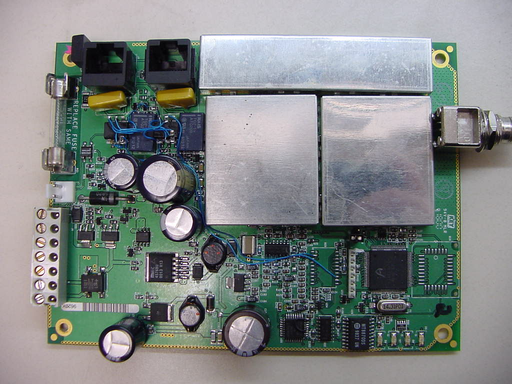
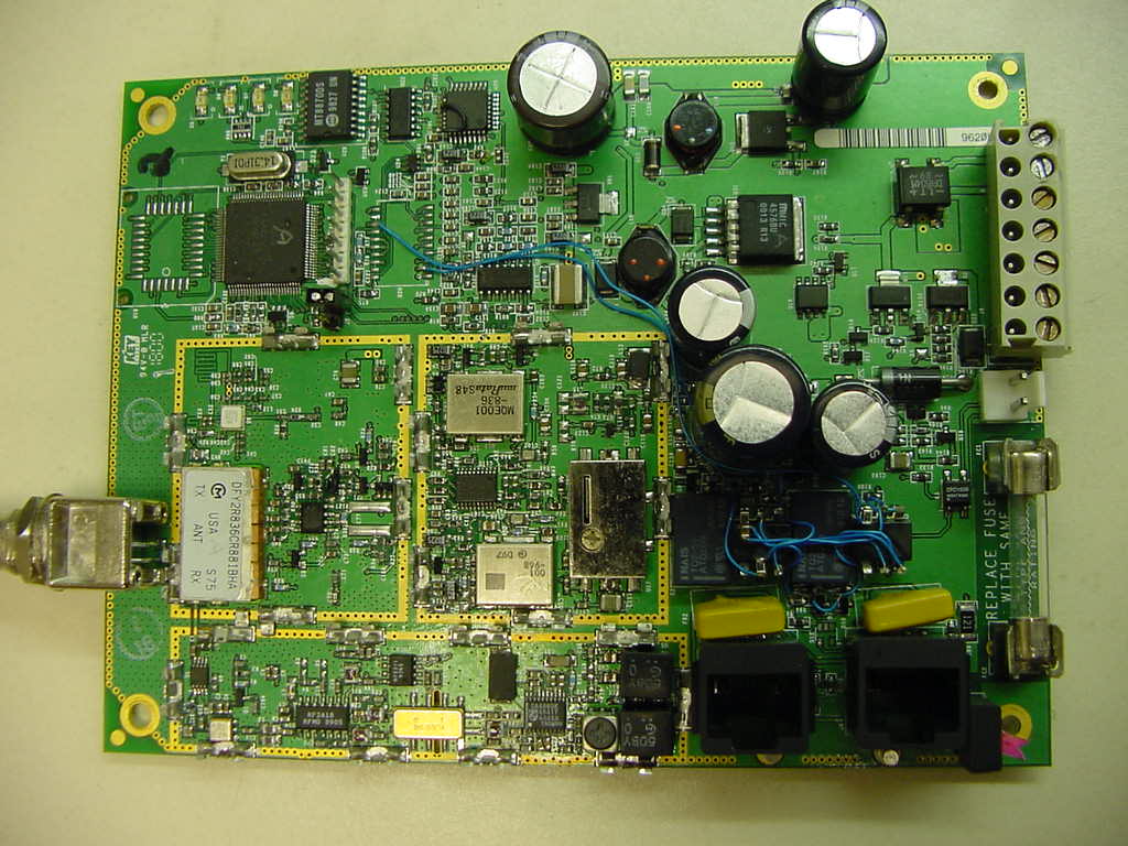
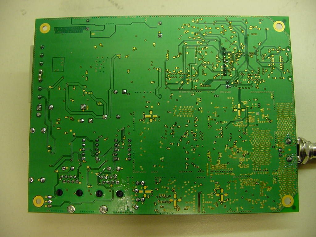
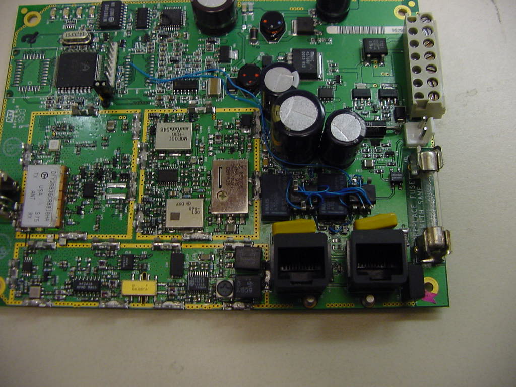
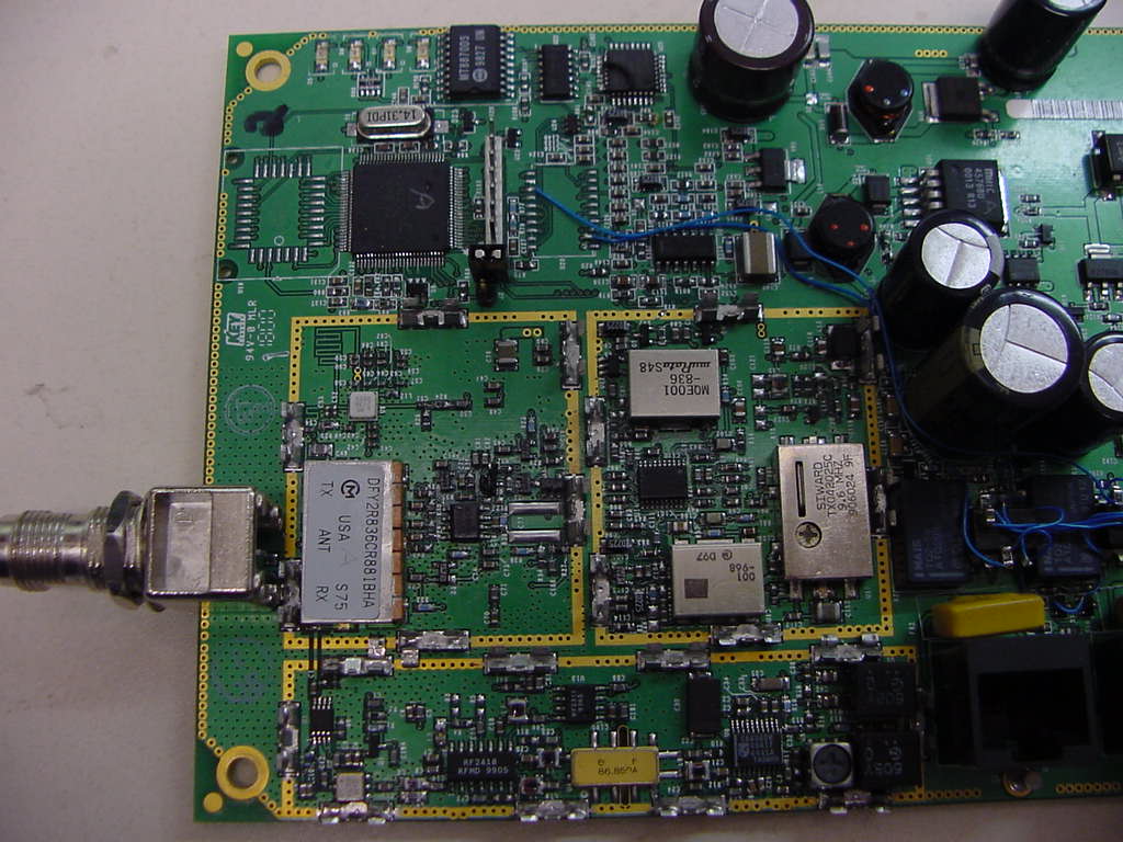
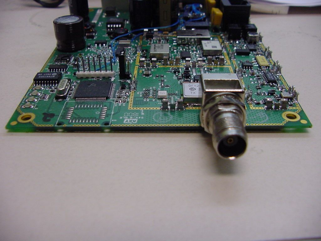
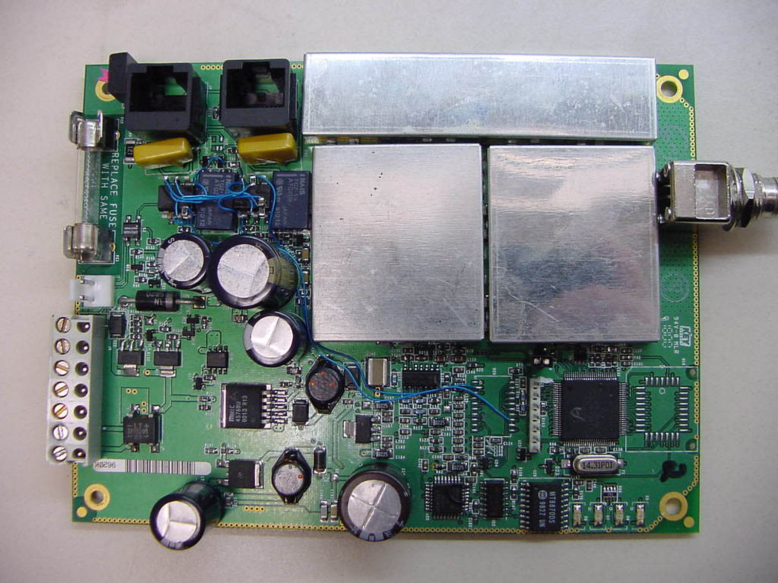
Assembly – T100C001
Internal Photos
Assembly – T100C001
Internal Photos
Assembly – T200C001
Operational Description
Ge ne ral De script io n (fro m Inst ructio n Ma nua l) All Telguard models come w ith a special Microburst™ compatible 3-w att cellular transceiver (without handset), antenna, interface w ith integrated control and pow er module, connecting cable, and plug-in transformer. The installer to provide backup times that range from twenty-four to seventy-two hours must supply a rechargeable 12V battery, 7.0AH or 14.0AH. Type of enclosure and type of antenna included are the only differences among the three models available. Economy model T100C001, UL Listed for Supplemental Use only, comes in a flame-retardant plastic enclosure (9½in.x4½in.x1¾in.) with w hip antenna. Model T200C001, UL Listed for residential and commercial fire, as well as residential burglary, comes in a standard metal enclosure (12in.x12in.x3½in.) with keylock and magnetic mount antenna with 12ft. of cable. Model T300C001, UL Listed for all residential burglary and fire, commercial burglary and fire, and bank applications comes in an attack-resistant enclosure with keylock, tamper switch, and magnetic mount antenna.
RF Exposure Info
RF Exposure Requirements The EUT is considered as a mobile device. Therefore the Electromagnetic Field Strength (E) was calculated and compared with FCC Maximum Permissive Exposure (MPE) limit. The Power Density (S) can be calculated using the formula S = (30 × EIRP) / (120 × π) / D2 (W/m2) The maximum EIRP in dBm equal P + G −cl= 35.6 + 5 −2=38.6 dBm or 7.24 W. Therefore, S = 0.576/ D2 (W/m2) The Duty Cycle can be taking into account. S = 0.576 × DC/ D 2 According Microburst protocol, the worst case of Duty Cycle (DC) is 16.7%, (e.g. the transmitter in ON for 3 s, and OFF for 15 s). However, in practice in back-up mode, once an hour the resulting transmitter DC would be approximately 0.08%. In the Table below is shown the MPE calculated data for different distances, for DC=0.167, DC=0.0008, and the FCC Limit, which for uncontrolled environment equal F/1500 (mW/cm 2 ) or F/150 (W/m 2 ) where F is a frequency in MHz. F=836.5 MHz Distance. mCalculated S, W/ m 2 DC=0.167 Calculated S, W/ m 2 DC=0.0008 MPE Limit W/ m 2 0.19.620.0465.58 0.22.400.0125.58 0.31.070.0055.58 0.40.600.0035.58 0.50.380.0025.58 For a 16.7% Duty Cycle the power density at a distance of 0.2 meters is 3.6 dB below the MPE limit. Therefore, to comply with MPE requirements, the maximum permissible antenna gain shall not exceed 8.6 dBi. In actual usage environment in backup mode as justified by customer the duty cycle would be approximately 0.08%. The calculated Power density is 0.012 W/ m 2 . This is 26.7 dB below the MPE limit of 5.58 W/ m 2 . The maximum permissible antenna gain shall be 31.7 dBi.
Test Report
Spurious Emissions Attenuation Measured by Substitution Method Company: Telular Inc EUT: Telgurad FCC ID: MTF 09000 Model:T100C001 Frequency MHz Field Strength Measured from EUT dBuV/m Signal Generator Level required to generate same field as EUT, dBm ERP * dBm Sp urio us Emissi o n Attenuation dB 824.04131.928.3- 1648.0869.9-40.30-35.463.7 2472.1267.5-36.50-31.0059.30 3296.1671.3-32.70-26.7055.00 4120.2065.1-39.00-33.0061.30 4944.2469.7-34.50-27.9056.20 5768.2859.1-47.40-40.8069.10 6592.3265.7-39.40-31.5059.80 7416.3665.1-39.60-31.8060.10 8240.4065.1-40.10-31.2059.50 *Numbers in this column were obtained by adding gain of Double Ridged Antenna (in dBd) relative to Half Wave dipole to the Signal Generator level required to obtain same field as EUT (Previous Column). Spurious Emissions Attenuation Measured by Substitution Method Company: Telular Inc EUT: Telgurad FCC ID: MTF 09000 Model:T100C001 Frequency MHz Field Strength Measured from EUT dBuV/m Signal Generator Level required to generate same field as EUT, dBm ERP * dBm Sp urio us Emissi o n Attenuation dB 836.47131.928.3- 1672.9466.3-43.00-38.166.4 2509.4161.3-46.20-40.7069.00 3345.8861.5-43.20-37.2065.50 4182.3566.5-37.30-31.3059.60 5018.8264.7-40.60-34.0062.30 5855.2965.8-39.70-33.1061.40 6691.7665.8-40.00-32.1060.40 7528.2367.8-37.40-29.6057.90 8364.7066.2-40.60-31.7060.00 *Numbers in this column were obtained by adding gain of Double Ridged Antenna (in dBd) relative to Half Wave dipole to the Signal Generator level required to obtain same field as EUT (Previous Column). Spurious Emissions Attenuation Measured by Substitution Method Company: Telular Inc EUT: Telgurad FCC ID: MTF 09000 Model:T100C001 Frequency MHz Field Strength Measured from EUT dBuV/m Signal Generator Level required to generate same field as EUT, dBm ERP * dBm Sp urio us Emissi o n Attenuation dB 848.97131.928.3- 1697.9465.3-45.20-40.368.6 2546.9161.9-41.20-35.7064.00 3395.8862.5-43.90-37.9066.20 4244.8568.9-40.10-34.1062.40 5093.8260.4-45.10-38.5066.80 5942.7965.6-41.00-34.4062.70 6791.7665.1-41.00-33.1061.40 7640.7366.5-40.10-32.3060.60 8489.7066.4-41.20-32.3060.60 *Numbers in this column were obtained by adding gain of Double Ridged Antenna (in dBd) relative to Half Wave dipole to the Signal Generator level required to obtain same field as EUT (Previous Column).
Test Setup Photos
Telular Technology FCC ID: MTF09000 Test Setup Photos (Radiated Emission) Telular Technology FCC ID: MTF09000 Test Setup Photos (Line Conducted Emission)
Test Setup Photos
Telular Technology FCC ID: MTF09000 Test Setup Photos (With Dipole Antenna) Telular Technology FCC ID: MTF09000 Test Setup Photos (With 3dB MAG Antenna) Telular Technology FCC ID: MTF09000 Test Setup Photos (With 5dB MAG Antenna)
Contact Information
Applicant
Jerry Talen(Director - Quality Assurance)
Technical Contact
Intertek Testing ServicesDavid Chernomordik
[email protected]650-463-2900
1365 Adams Court · Menlo Park, California · United States
Non-Technical Contact
Telular CorporationRex Nathanson
[email protected]631-232-6070
Test Firm
Intertek Testing Services NA Inc.John Quigley
Technical Specifications
| # | Rule Parts | Frequency Range | Power Output | Emission | Tolerance |
|---|---|---|---|---|---|
| 1 | 22H | 824 MHz - 849 MHz | 3.6 W | 40K0F1D | 2.5000000000 ppm |
Other Applications from Telular Corporation
MTFST1002
Dec 01, 2025Telematic Gateway for Communicating Measurement Data
Equipment Class
DTS - Digital Transmission SystemMTFSHB6510
Jul 24, 2022Asset Tracking
Equipment Class
DTS - Digital Transmission System
MTFSHB1000
Nov 12, 2020SkyHub Wireless Telematics Hub
Equipment Class
PCB - PCS Licensed Transmitter
MTFTL9XC
Jan 03, 2016Wireless Tank Monitor Model TL9X, Client
Equipment Class
DTS - Digital Transmission System
MTFTG5112597A
Nov 14, 2007Residential & Business Cellular Alarm Communicator
Equipment Class
PCB - PCS Licensed Transmitter