MTFGSMUSDUALPhoneCell SX5
Telular Corporation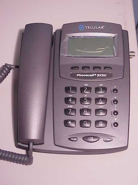
Click to zoom
Application Details
- Equipment Class
- PCB - PCS Licensed Transmitter
- Date of Grant
- Sep 30, 2003
- Application Purpose
- Original Equipment
- Date of Application
- Sep 30, 2003
- Equipment Note
- PhoneCell SX5
- Frequency Range
- 1850.20000000 - 1909.80000000
- Company
- Telular Corporation
- Country
- United States
Documents & Files
Document Text
Text extracted from the exhibit documents filed with the FCC. Open a document above to read the original.
Users Manual
7/28/03Part Number 56029701 PHONECELL ® SX5D GSM • Fixed Wireless Phone • Fixed Wireless Fax Phone • Fixed Wireless LCR Phone 850/1900 MH ZGSM (DUALBAND) USERMANUAL Phonecell ® SX5D GSMiUser Manual QUICK CONNECTION GUIDE Fixed Wireless Phone Fixed Wireless FAX Phone Phonecell ® SX5D GSMiiUser Manual Fixed Wireless Personal Least Cost Routing (LCR) Phone Phonecell ® SX5D GSMiiiUser Manual SX5D MENU STRUCTURE Phonebook View Names Add Name Settings Messages Received Messages Saved Messages Create Message Message Settings Voicemail Info Message Clock Set Alarm Clock Settings Set Time Set Date Set Time Zone Settings Phone Settings Audio Settings Call Settings Data Settings Fax Settings* Extension Settings* Dial Settings Network Settings Security Settings Restore Defaults Service Settings** Call Log All Calls Missed Calls Received Calls Dialed Numbers Clear Logs Call Time GPRS Info Call Divert All Calls When Busy No Answer Not Found Cancel All Diverts * Not available on all models ** Requires password Menu Phonecell ® SX5D GSMivUser Manual Before installing your Phonecell ® SX5D, carefully remove the contents from the shipping carton and check for evidence of shipping damage. If damage is found, contact your Authorized Telular Distributor or shipping agent immediately. SAFE OPERATION INSTRUCTIONS IMPORTANT!Before installing or operating this product, read the SAFETY INFORMATION section of this manual. •• Install unit indoors. •• Install unit on hard, flat surface for proper ventilation. •• Do not expose unit to rain or moisture. •• Do not place unit on or close to sources of heat IMPORTANT NOTICES TERMS AND CONDITIONS FOR USE OF PHONECELL ® PRODUCTS ("Product") These Terms and Conditions are a legal contract between you and Telular Corporation for the title to and use of the Product. BY RETAINING AND USING THE PRODUCT AFTER RECEIPT OF IT, YOU AGREE TO THE TERMS AND CONDITIONS INCLUDING WARRANTY DISCLAIMERS, LIMITATIONS OF LIABILITY AND INDEMNIFICATION PROVISIONS BELOW. IF YOU DO NOT AGREE TO THE TERMS AND CONDITIONS, DO NOT USE THE PRODUCT AND IMMEDIATELY RETURN THE UNUSED PRODUCT FOR A COMPLETE REFUND. You agree to accept sole responsibility for any misuse of the Product by you; and, in addition, any negligent or illegal act or omission of your or your agents, contractors, servants, employees, or other users of the Product so long as the Product was obtained from you, in the use and operation of the Product. INDEMNIFICATION OF TELULAR CORPORATION ("TELULAR") YOU SHALL INDEMNIFY, DEFEND AND HOLD HARMLESS TELULAR FOR ANY OF THE COST, INCLUDING REASON- ABLE ATTORNEYS' FEES, AND FROM CLAIMS ARISING OUT OF YOU, YOUR CLIENTS' OR OTHER THIRD PARTIES' USE OR OPERATION OF THE PRODUCT: (i) FOR MISUSE OR IN A MANNER NOT CONTEMPLATED BY YOU AND TELULAR OR INCONSISTENT WITH THE PROVISIONS OF THIS MANUAL; (ii) IN AN ILLEGAL MANNER OR AGAINST PUBLIC POLICY; (iii) IN A MANNER SPECIFICALLY UNAUTHORIZED IN THIS MANUAL; (iv) IN A MANNER HARMFUL OR DANGEROUS TO THIRD PARTIES; (v) FROM CLAIMS BY ANYONE RESPECTING PROBLEMS, ERRORS OR MIS- TAKES OF THE PRODUCT; OR (vi) COMBINATION OF THE PRODUCT WITH MATERIAL, MODIFICATION OF THE PRODUCT OR USE OF THE PRODUCT IN AN ENVIRONMENT NOT PROVIDED, OR PERMITTED, BY TELULAR IN WRIT- ING. THE PARTIES SHALL GIVE EACH OTHER PROMPT NOTICE OF ANY SUCH COST OR CLAIMS AND COOPER- ATE, EACH WITH THE OTHER, TO EFFECTUATE THIS INDEMNIFICATION, DEFENSE AND HOLD HARMLESS. TELULAR CORPORATION Corporate Headquarters 647 North Lakeview Parkway Vernon Hills, Illinois 60061, USA Technical Support Tel: 847-247-9400 • Fax: 847-247-0021 E-mail: [email protected] • http://www.telular.com Power Supply Phonecell ® SX5D GSM Desktop Phone Spike Antenna PLEASE SEE THE IMPORTANT NOTICES SECTION OF THIS MANUAL FOR IMPORTANT INFORMATION ON USE, WARRANTY AND INDEMNIFICATION CONTENTS AC Power Cord Part Number 56029801©2003 Telular Corporation, All Rights Reserved Phonecell ® SX5D GSMvUser Manual TABLE OF CONTENTS Quick Connection Guide..................................................................................................i SX5D Menu Structure ....................................................................................................iii Contents .........................................................................................................................iv Safe Operation Instructions ...........................................................................................iv Important Notices ...........................................................................................................iv SX5D Setup ....................................................................................................................1 SIM Card Installation .................................................................................................1 Emergency Batteries .................................................................................................1 Location and Setup....................................................................................................2 Connect the Handset .................................................................................................2 Desk-Mounting...........................................................................................................3 Wall-Mounting ............................................................................................................4 Connect the SX5D to AC Power................................................................................5 Getting to Know Your SX5D ...........................................................................................6 Function Keys ............................................................................................................6 LCD Screen Icons......................................................................................................7 Hearing Aid Compatibility...............................................…
Text truncated - open the document above for the full version.
Users Manual
7/31/03 Part Number 56029901 PHONECELL ® SX5e GSM • Fixed Wireless Terminal • Fixed Wireless Terminal with Fax • Fixed Wireless PBX Terminal • Fixed Wireless Modem 850/1900 MHZGSM (DUALBAND) USERMANUAL Phonecell ® SX5e GSMiiUser Manual QUICK CONNECTION GUIDE SX5e Fixed Wireless Terminal with Optional Analog Fax SX5e Fixed Wireless Terminal Phonecell ® SX5e GSMiiiUser Manual Extension Side Trunk Side SX5e Fixed Wireless PBX Terminal (attached to Extension side of PBX) SX5e Fixed Wireless PBX Terminal (attached to Trunk side of PBX) Phonecell ® SX5e GSMivUser Manual SX5e Fixed Wireless Modem Phonecell ® SX5e GSMvUser Manual Before installing the Phonecell ® SX5e, carefully remove the contents from the shipping carton and check for evidence of shipping damage. If damage is found, contact your Authorized Telular Distributor or shipping agent immediately. SAFE OPERATION INSTRUCTIONS IMPORTANT!Before installing or operating this product, read the SAFETY INFORMATION section of this manual. •• Install the unit indoors. •• Install the unit on a hard, flat surface for proper ventilation. •• Do not expose the unit to rain or moisture. •• Do not place the unit on or close to sources of heat. IMPORTANT NOTICES TERMS AND CONDITIONS FOR USE OF PHONECELL ® PRODUCTS ("Product") These Terms and Conditions are a legal contract between you and Telular Corporation for the title to and use of the Product. BY RETAINING AND USING THE PRODUCT AFTER RECEIPT OF IT, YOU AGREE TO THE TERMS AND CONDITIONS INCLUDING WARRANTY DISCLAIMERS, LIMITATIONS OF LIABILITY AND INDEMNIFICATION PROVISIONS BELOW. IF YOU DO NOT AGREE TO THE TERMS AND CONDITIONS, DO NOT USE THE PRODUCT AND IMMEDIATELY RETURN THE UNUSED PRODUCT FOR A COMPLETE REFUND. You agree to accept sole responsibility for any misuse of the Product by you; and, in addition, any negligent or illegal act or omission of your or your agents, contractors, servants, employees, or other users of the Product so long as the Product was obtained from you, in the use and operation of the Product. INDEMNIFICATION OF TELULAR CORPORATION ("TELULAR") YOU SHALL INDEMNIFY, DEFEND AND HOLD HARMLESS TELULAR FOR ANY OF THE COST, INCLUDING REASON- ABLE ATTORNEYS' FEES, AND FROM CLAIMS ARISING OUT OF YOU, YOUR CLIENTS' OR OTHER THIRD PARTIES' USE OR OPERATION OF THE PRODUCT: (i) FOR MISUSE OR IN A MANNER NOT CONTEMPLATED BY YOU AND TELULAR OR INCONSISTENT WITH THE PROVISIONS OF THIS MANUAL; (ii) IN AN ILLEGAL MANNER OR AGAINST PUBLIC POLICY; (iii) IN A MANNER SPECIFICALLY UNAUTHORIZED IN THIS MANUAL; (iv) IN A MANNER HARMFUL OR DANGEROUS TO THIRD PARTIES; (v) FROM CLAIMS BY ANYONE RESPECTING PROBLEMS, ERRORS OR MIS- TAKES OF THE PRODUCT; OR (vi) COMBINATION OF THE PRODUCT WITH MATERIAL, MODIFICATION OF THE PRODUCT OR USE OF THE PRODUCT IN AN ENVIRONMENT NOT PROVIDED, OR PERMITTED, BY TELULAR IN WRITING. THE PARTIES SHALL GIVE EACH OTHER PROMPT NOTICE OF ANY SUCH COST OR CLAIMS AND COOP- ERATE, EACH WITH THE OTHER, TO EFFECTUATE THIS INDEMNIFICATION, DEFENSE AND HOLD HARMLESS. PLEASE SEE THE IMPORTANT NOTICESSECTION OF THIS MANUAL FOR IMPORTANT INFORMATION ON USE, WARRANTY AND INDEMNIFICATION CONTENTS Telular Corporation Corporate Headquarters 647 North Lakeview Parkway Vernon Hills, Illinois 60061, USA Technical Support Tel: 847-247-9400 • Fax: 847-247-0021 E-mail: [email protected] • http://www.telular.com Phonecell ® SX5e GSM FWTSpike Antenna Part Number 56029901©2003 Telular Corporation, All Rights Reserved Power Supply AC Power Cord Phonecell ® SX5e GSMviUser Manual TABLE OF CONTENTS QUICK CONNECTION GUIDE ......................................................................................ii IMPORTANT NOTICES..................................................................................................v Technical Support.......................................................................................................v SETUP............................................................................................................................1 Install the SIM Card ...................................................................................................1 Emergency Batteries..................................................................................................2 SX5e Location and Installation ..................................................................................3 Wall Mounting.............................................................................................................3 Connect the SX5e to AC Power.................................................................................4 Attach a Telephone to the SX5e ................................................................................4 GETTING TO KNOW YOUR SX5e ................................................................................5 LED Status Indicators ................................................................................................5 Important Dial Tones ..................................................................................................6 CALL FUNCTIONS ........................................................................................................7 Making Calls...............................................................................................................7 Receiving Calls ..........................................................................................................7 Ending Calls ...............................................................................................................7 In-Call Features..........................................................................................................7 SX5e USER FEATURES................................................................................................8 Messages (Voice Mail and Text Messages)...............................................................8 Audio Settings .....................................................…
Text truncated - open the document above for the full version.
Cover Letter(s)
August 1, 2003 Reviewing Engineer Federal Communications Commission 7435 Oakland Mills Road Columbia, MD 21046 Subject: Confidentiality Request FCC ID: MTFGSMUSDUAL Products: SX5D GSM 850/1900 Deskphone SX5e GSM 850/1900 Fixed Wireless Terminal It is requested that the following items associated with this submission be held confidence in accordance with FCC Rule Section 0.459: a) Schematics b) Block diagram c) Parts List The reasons for withholding the above materials from inspection are trade secrets and substantial competitive harm. The above exhibits contain designs and information proprietary to Telular. This information is available only for internal company use, and is not available publicly. Public release of this information would allow competitors to copy key elements of Telular’s design, and also provide them with engineering specifications that have been based on Telular’s many years of experience. We feel that this material should be held confidential in perpetuity, because the trade secrets that are based on Telular’s years of experience will always be applicable to the design of a similar product. Sincerely, Daniel Giacopelli Executive Vice President
Cover Letter(s)
August 1, 2003 Reviewing Engineer Federal Communications Commission 7435 Oakland Mills Road Columbia, MD 21046 Subject: Letter of Agent Authorization FCC ID: MTFGSMUSDUAL Products: SX5D GSM 850/1900 Deskphone SX5e GSM 850/1900 Fixed Wireless Terminal We, the undersigned, hereby authorize Intertek Laboratories, Inc. to act on our behalf in all matters relating to application for equipment authorization, including the signing of all documents relating to these matters. We also hereby certify that no party to the application authorized hereunder is subject to the denial of benefits, including FCC benefits, pursuant to Section 5301 of the Anti-Drug Abuse Act of 1988,21 U.S.C.853(a). This agreement expires one year from the current date. Sincerely, Daniel Giacopelli Executive Vice President
Cover Letter(s)
-----Original Message----- From: David Schramm ES-Atl Sent: Monday, September 22, 2003 5:59 PM To: Roland Gubisch ES-Box Cc: Danielle Fontaine ES-Box Subject: FW: SX5 US Dual Band(FCC ID: MTFGS MUSDUAL) Roland, The client has answered Administrative items 1 and 2 below. I believe all that is left is Administrative item 3, which I will send shortly. Best regards, David Schramm -----Original Message----- From: John Papson To: David Schramm ES-Atl Cc: Matthew McKiernan Sent: 9/22/2003 9:12 AM Subject: RE: SX5 US Dual Band(FCC ID: MTFGS MUSDUAL) David: RE: Questions concerning Telular's 850/1900 GSM radio: > 1) Please provide information on DC voltage/current into final RF stage, > per 2.1033(c)(8). 3.6 volts at 2000 milliamperes maximum for 824 to 849 MHz power amp; 3.6 volts at 1500 milliamperes maximum for 1850 to 1919 MHz power amplifier. > 2) Please provide tune-up information, per 2.1033(c)(9). There are no mechanical tuning adjustments within the radio. Automated factory calibration program adjusts internal frequency standard, receive AGC, and transmit power levels, which are stored in non volatile RAM. John C Papson, Principal RF Engineer Telular Corporation 580 Old Willets Path Hauppauge, NY, USA 11788 Voice: (631) 232-6070 ex213 Fax: (631) 232 6082 Email: [email protected] From: David Schramm ES-Atl Sent: Thursday, September 11, 2003 4:58 PM To: Roland Gubisch ES-Box Cc: Danielle Fontaine ES-Box Subject: RE: Certification Review of Telular FCC ID: MTFGSMUSDUAL Roland, Please see my responses below. ADMINISTRATIVE 1) Request sent to customer. 2) Request sent to customer. 3) Request sent to customer. 4) Attached. 5) Request sent to Brian Tucker. Photographs and testing were performed. TECHNICAL 1) A base station simulator was used and was set to command the EUT to its maximum power level. 2) Table 3-1 contained a typo. 936.4 MHz is incorrect and should be 836.4 MHz. 3) a) The RBW was set to 3 kHz, which is greater than 1% of the emission bandwidth (i.e. 260 kHz x 0.01 = 2.6 kHz). b) For Part 24E, the RBW = VBW = 1 MHz. c) Request sent to customer. 4) a) 1.673 GHz was the intended frequency, not 1673 GHz. -----Original Message----- From: Roland Gubisch ES-Box Sent: Friday, September 05, 2003 2:15 PM To: David Schramm ES-Atl Cc: Brian Tucker ES-Lex; Danielle Fontaine ES-Box Subject: Certification Review of Telular FCC ID: MTFGSMUSDUAL David: Review of this application is complete, and the following points are noted: ADMINISTRATIVE 1) Information on DC voltage/current into final RF stage cannot be found, per 2.1033(c)(8); please indicate location or provide. 2) Tune-up information cannot be found, per 2.1033(c)(9); please indicate location or provide. 3) The parts list provided in the application is a top-level assembly list, and contains no information about the components in the RF circuitry; please provide. 4) External photos of the SX5E model cannot be found; please indicate location or provide. 5) Setup photos of the SX5E model cannot be found; please provide, or submit a justification why testing was not done. TECHNICAL 1) Conducted and radiated output power, test report sections 3 and 4: please describe the method used to set maximum power. Was a base station simulator used, or an internal program? 2) Table 3-1, conducted output power; the frequency 936.4 MHz appears as a typo; please confirm it should be 836.4 MHz. 3) Out of band emissions, report section 6: a) please indicate the specific RBW values used for measurements within 1 MHz from the outside of the block edge; they are not shown in the report. b) the RBW value of 100 kHz listed in 6.1 for emissions beyond 1 MHz from the block edge is only valid for Part 22H. What RBW value was used for 22E data? 5) Table 7-1, spurious radiated emissions a) the frequency 1673 MHz appears as an apparent typo; please confirm that 1.673 MHz was intended. Once these issues are resolved, the application can proceed to certification. Thank you, Roland Gubisch Intertek TCB
External Photos
Figure 1: Overview Figure 2: Rear view Figure 3: Rear view
External Photos
External Photographs of the SX5E FCC ID: MTFGSMUSDUAL Figure 1: Top View External Photographs of the SX5E FCC ID: MTFGSMUSDUAL Figure 2: Close-up View of LEDs External Photographs of the SX5E FCC ID: MTFGSMUSDUAL Figure 3: View of I/O ports and dc input port External Photographs of the SX5E FCC ID: MTFGSMUSDUAL Figure 4: Antenna port External Photographs of the SX5E FCC ID: MTFGSMUSDUAL Figure 5: Bottom view
ID Label/Location Info
ES025A (6-94) DRAWNBY: DRAWING NUMBER: APPROVEDBY: DES. ENG.MFG.MECH. DESIG. TITLE: DATE: SHT. OF 11 LABEL, PHONECELL SX5 GSM 850/1900 ASSEMBLY 96027305 08/01/03 D. TOBIAS P. WOJCIK NOTE:1.2. TEXT FONTS, SIZE AND LOCATION SHALL BE APPROVED BY THE MARKETING DEPARTMENT PRIOR TO VOLUME PRODUCTION. 3. BARCODES TO BE CODE 128.4. AAAAAAAA TO BE REPLACED WITH IMEI OF UNIT.5. YYWWLTXXXX TO COMPLY WITH TELULAR SPEC. 90006502.6. NNNNNNNN TO BE REPLACED WITH TELULAR MODEL NUMBER.7. DDDDDDDDDDD TO BE REPLACED WITH ABBREVIATED PRODUCT MODEL DESCRIPTION. 8. RR TO BE REPLACED WITH PRODUCT REVISION IDENTIFIER.9. MMMMMM TO BE REPLACED WITH COUNTRY OF MANUFACTURE. MATERIAL: 2“ x 1” ADHESIVE-BACKED WHITE POLYESTER: ZEBRA #65598 (Z-ULTIMATE 3000 WHITE LABEL)ZEBRA #5095BK (06045 2.36” X 450 METER BLACK RESIN RIBBON) N. JOSLYN D. KRASOWSKI D. TOBIAS FCC ID: MTFGSMUSDUAL Model No.: NNNNNNNN IMEI: AAAAAAAAAAAAAAAA S/N: YYWWLTXXXX MADE IN MMMMMM DESC: DDDDDDDDDDDDDD REV.: RR
Internal Photos
Figure 1: Inside view of top and bottom cover – SX5D Figure 2: Inside top cover – SX5D Figure 3: Bottom cover wit circuit boards installed – SX5D Figure 4: Inside bottom cover with circuit board details – SX5D Figure 5: Inside top cover – SX5e Figure 6: Inside bottom cover – SX5e Figure 7: Inside bottom cover with circuit board details – SX5e
Operational Description
R R CORPORATION Technology Center Technical Description SX5 GSM 850/1900 RADIO August 1, 2003 z Page 2 This document details the functional description of the GSM 850/1900 Mobile Stations (MS). This assembly consists of two major sub-systems: The RF/IF processor The GSM processor and Baseband codec The RF/IF processor is based on the Analog Devices “Othello” radio and the baseband platform is comprised of the Analog Devices “430” chip set . The chip set contains four ICs, The AD6523 Transceiver, the AD 6524 Frequency Synthesizer, the AD6522 GSM processor and the AD6521 baseband codec. A functional block diagram of the Radio is depicted in figure 1. This is a GSM Phase 2 compliant MS, that provides voice and data/fax capability. The RF part of the assembly operates in the GSM 850 frequency band (uplink 824 - 849 MHz, downlink 869 - 894 MHz) and forms a Class 1 MS, capable of delivering 2 Watts at the RF connector. It also operates in the GSM1900 frequency band (uplink 1850-1910 MHz, downlink 1930-1990 MHz) and forms a Class 1 MS, capable of delivering 1 Watts at the RF connector. Figure 1.GSM Radio architecture GSM Mobile Terminal Block Diagram Flash Loader Control AT Interface GSM Clock Out Power 03/19/02 SX5 techdesc 1900.doc Reset SRAM EE PROM FLASH ROM SIM Logic VBC AD6521 RF Section Synthesizer AD6524ARU T/R External SIM Interface Radio Comand Interface Audio Signals GPIO 5 RF Antenna Interface Rx Filter & LNA RF/IF Processor AD6523ARU "Othello" Power Control PA GSM Processor AD6522 Serial Port 1 Serial Port 3 Serial Port 2 IQ TX VCO AFC ramp Power AUDIO LPF Reset LO VCO 13 MHz FREQ REF August 1, 2003 z Page 3 1. Local Oscillator The entire radio module uses a single frequency reference of 13.000 MHz. A Voltage Controlled Variable Crystal Oscillator (TCVCXO) with AFC capability is employed to utilize the frequency stability of the GSM link. The baseband processor chip supplies the AFC control voltage. All frequency sources are derived coherently from this crystal reference. Common to the transmitter and receiver is a Phase Locked Loop (PLL) controlled Local Oscillator that operates at exactly 3/4ths of the current transmit or receive channel center frequency in the 1900 band. The channel frequency is set by programming counters within the Synthesizer IC via a digital word from the baseband processor. 2. Transmitter The transmit path of the system consists of a burst store, a GMSK modulator and two high- speed DACs with output spectrum shaping FIR filters. These filters provide the 0.3 GMSK waveform required for the GSM system. The RF chip contains a vector modulator, a phase detector, down-converter mixer and two dividers. The Vector Modulator is used as a reverse-modulator in a translation loop, which in turn modulates the transmit VCO. This architecture is illustrated in figures 2a and 2b. Figure 2a. RF Transmitter architecture – GSM 1900 I&Q MOD 1850-1910 MHz VCO 1850 –1910 MHz PLL 1387.65 – 1432.35 MHz VCO 13 MHz TCVCXO ANTENNA SWITCH / LOW PASS FILTER I Q 462.55 to 477.45 RAMP Pwr Cntrl AFC Divide by 6 Divide by 2 462.55 to 477.45 231.275 to 238.725 MHz Chan TXIF August 1, 2003 z Page 4 Figure 2b. RF Transmitter architecture – GSM 850 The Vector Modulators Carrier input is fed with a down converted version of the transmitter output (called the TXIF) containing the full GMSK modulation index. The I and Q baseband GMSK transmit modulation signals from the D/A converter are applied to the Vector Modulator. The resulting output from the Vector Modulator is a carrier at exactly 1/4 th the AFRCN carrier frequency, with some residual error signal. (The loop drives the output from the Vector Modulator to as pure a carrier signal as possible, in the process impresses an exact copy of the I-Q transmit waveform onto the main Transmit VCO.) This resulting carrier plus residual error signal is divided by two and then applied to a phase/frequency detector which uses a pure carrier signal counted down from the Local Oscillator as it’s reference. The Phase Frequency Detector drives a Charge Pump and Loop Filter. The error voltage is then used to tune the transmit VCO to the exact ARFCN channel frequency. (It should be noted that the TXIF is always exactly one fourth the transmit frequency.) The output of the transmit VCO carries the original GMSK information and is fed to RF power amplifier. The peak output power and the profile of the transmitted burst are controlled by means of a closed feedback loop, which is directed by the baseband processor. I&Q MOD 824 - 849 MHz VCO 824 – 869 MHz PLL 1236.30 – 1273.20 MHz VCO 13 MHz TCVCXO ANTENNA SWITCH / LOW PASS FILTER I Q 412.10 to 424.40 RAMP Pwr Cntrl AFC Divide by 6 Divide by 2 412.10 to 424.40 206.05 to 212.20 MHz Chan TXIF August 1, 2003 z Page 5 The final RF output passes to the antenna connector through an integrated TX/RX switch and lowpass filter to attenuate the harmonics generated by the power amplifier. 3. Receiver The receiver subsystem is a direct conversion receiver to baseband. The pictorial presentation is illustrated in figures 3a and 3b below. The RF signal enters the receiver through the TX/RX switch. This is followed by a 881.5 MHz or 1960 MHz SAW bandpass filter and a low–noise amplifier. The signal passes via a BALUN transformer to the receive down-converter. The receiver Local Oscillator, operating at exactly 3/2 (or 3/4 th for PCS Band) of the channel frequency is converted to 0 and –90 degree oscillator signals needed by the Down- Converter, exactly on channel via a regenerative divider internal to the Receiver IC. Use of this internal regenerative divider solves the problems of local oscillator leakage paths upsetting the balance of the following mixers. The mixer multiplies the RF frequency with the 1 st LO, and produces I & Q baseband signals. DC offsets within the mixer are calibrated out. The Baseband outputs are then filtered and pass to the dual AGC amplifiers. A succession of L/C and digital filters internal to the r…
Text truncated - open the document above for the full version.
Operational Description
Phonecell ® SX5D Fixed Wireless F·A·X Phone • Voice • GPRS Packet Data • Circuit Switched Data • Short Message Service (SMS) • Group 3 Analog Fax • Circuit Switched Computer Fax Also Featuring ✓Access the Internet and E-Mail ✓Dual RJ-11 connections for multiple extensions ✓Automatic end-of-dialing (no SEND key) ✓Caller ID, call waiting/call hold, call forwarding ✓Speakerphone ✓Large, easy to read LCD ✓PC keyboard can be attached for text messaging ✓Easy set up Models • Dual Band 900/1800 GSM Phase 2+ • Dual Band 850/1900 GSM Phase 2+ Compact design for voice, data, FAX AND MULTIPLE EXTENSIONS (F·A·X) Fixed Wireless F·A·X Phone Features •GPRS packet data, multi-slot Class 10 (up to 85.6 kbps)* • Circuit switched digital computer fax and data (up to 14.4 kbps)* •Short Message Service (SMS)* • Group 3 analog fax* •Compatible with popular supplementary services including caller ID, call waiting/call hold, call forwarding, call barring, multi-party calling, and more* • DTMF keypad with half duplex speakerphone, mute, redial and flash • Fully pixilated LCD display for text messaging, phone book, set up, signal-strength indication, etc. • Soft key access to menu, voice mail, SMS and phone book • Speed dial • Volume control and configurable rings per service •Call logs, clock and call timer • Extensive security control features • Built-in signal-strength indication • Single jack or dual jack for voice and fax operation •DTMF and pulse-dialing •Automatic end-of-dialing (no SEND key) • Supports up to five phones (5 REN) • Emergency battery backup • Simple desktop or wall-mount installation •Standard GSM Mini-SIM (Subscriber Identification Module) 3 volt and 5 volt compatible • Supports SIM Application Toolkit •Supports GSM personalization features (GSM 02.22) Connectivity Options Models •Dual Band 900/1800 GSM Phase 2+ •Dual Band 850/1900 GSM Phase 2+ Specifications Air Interface Standard • GSM 900/1800 Phase 2+ • GSM 850/1900 TIA/EIA J-STD-007 Transmit Power • GSM 850 & 900: 2 watts • GSM 1800 & 1900: 1 watt Frequency Ranges Transmit Receive • GSM 850824-849 MHz869-894 MHz •GSM 900890-915 MHz935-960 MHz •GSM 18001710-1785 MHz1805-1880 MHz • GSM 19001850-1910 MHz1930-1990 MHz FWT Dimensions and Weight • Metric (cm) 18.3 x 5.1 x 21.1 • U.S. (inches) 7.2 x 2.0 x 8.3 • 0.73 kg. (1.6 lb.) Environment • Operating temperature range: -10°C to +50°C • Storage temperature range: -40°C to + 60°C • Humidity: 5% to 95% Intelligent RJ-11 Interface • Ringer equivalence number (REN) 5.0A • Dynamic echo cancellation • PSTN Emulation LCD Display • Resolution: 64 pixels high x 132 pixels long • Characters: Icons and alphanumeric • Adjustable contrast Connectors • RJ-11 interface jack for telephone • RJ-11 interface jack for Group 3 analog fax • DB-9 port for GPRS or circuit switched digital PC fax/data •DIN connector for PC keyboard • TNC antenna connector (50 ohms) • DC power input jack Antenna • Dipole antenna (included) GSM 900/1800: 2 dBi dual band GSM 850/1900: 2 dBi dual band • Optional higher gain antennas available AC-to-DC Switching Power Supply (Included) • Voltage: 90 - 300 VAC • Frequency: 50/60 Hz • Plug options: U.S., U.K., Euro., Australia Emergency Battery Backup • 4 “AA” alkaline batteries provide up to 1 hour of air time. (Batteries not included.) External Battery Backup (Optional) • External battery backup unit/charger (provides up to 8 hours of air time or 14 hours of standby) Phonecell ® SX5D Copyright ©2003 Telular Corporation, all rights reserved. SX5DGSM V/PC FAX 05/03 • Specifications subject to change without notice. Drawings may vary from actual equipment supplied. Telular Corporation •Corporate Headquarters•647 North Lakeview Parkway •Vernon Hills, Illinois 60061 USA Phone: 847-247-9400 • Fax: 847-247-0021 • E-mail: [email protected] • http://www.telular.com Europe/Middle East/Africa• Phone: +44-1753-486-500 • [email protected] Latin America• Phone: +1-954-217-0522 • [email protected] Asia/Pacific• Phone: +65-6735-7728 • [email protected] * Subject to network availability. Computer (Internet, E-Mail, Fax, Data) Serial Port AC Power Power Supply External Battery Backup Unit w/Power Supply (optional) Phone (Voice) Phone Port Keyboard (SMS) Keyboard Port Fax Machine Fax Port
Operational Description
• …
Text truncated - open the document above for the full version.
Contact Information
Applicant
Jerry Talen(Director - Quality Assurance)
Technical Contact
IntertekDavid Schramm
[email protected]678 775 2413
1950 Evergreen Blvd. · Duluth, Georgia · United States
Non-Technical Contact
IntertekDavid Schramm
[email protected]978 775 2413
Test Firm
Intertek Testing ServicesDavid Schramm
Technical Specifications
| # | Rule Parts | Frequency Range | Power Output | Emission | Tolerance |
|---|---|---|---|---|---|
| 2 | 24E | 1.85 GHz - 1.91 GHz | 630.00 mW | 260KGXW | 211 Hz |
Other Applications from Telular Corporation
MTFST1002
Dec 01, 2025Telematic Gateway for Communicating Measurement Data
Equipment Class
DTS - Digital Transmission SystemMTFSHB6510
Jul 24, 2022Asset Tracking
Equipment Class
DTS - Digital Transmission System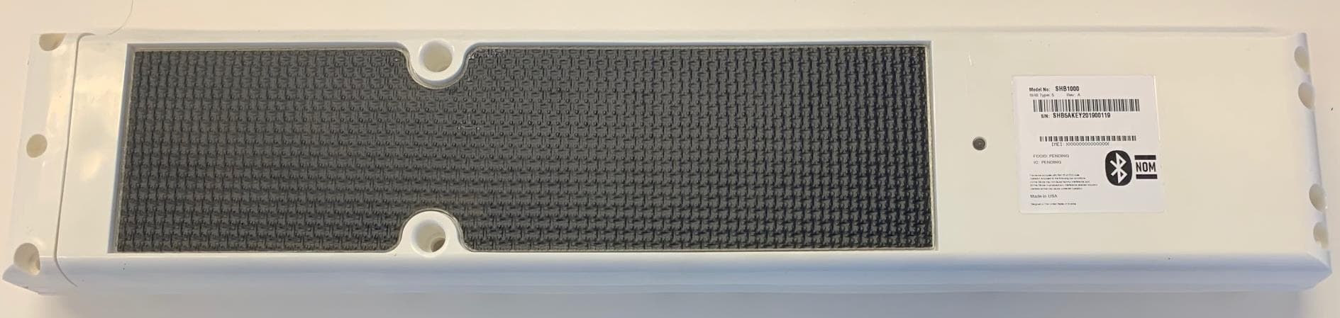
MTFSHB1000
Nov 12, 2020SkyHub Wireless Telematics Hub
Equipment Class
PCB - PCS Licensed Transmitter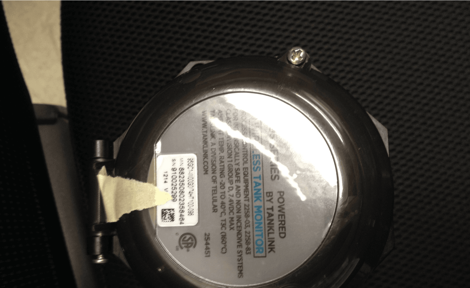
MTFTL9XC
Jan 03, 2016Wireless Tank Monitor Model TL9X, Client
Equipment Class
DTS - Digital Transmission System
MTFTG5112597A
Nov 14, 2007Residential & Business Cellular Alarm Communicator
Equipment Class
PCB - PCS Licensed Transmitter