MTFTG5112597Telguard 5 Alarm System Communicator, TG5A0001
Telular Corporation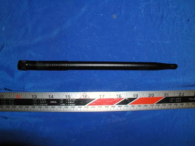
Click to zoom
Application Details
- Equipment Class
- PCB - PCS Licensed Transmitter
- Date of Grant
- Oct 30, 2003
- Application Purpose
- Original Equipment
- Date of Application
- Oct 30, 2003
- Equipment Note
- Telguard 5 Alarm System Communicator, TG5A0001
- Frequency Range
- 1850.20000000 - 1909.80000000
- Company
- Telular Corporation
- Country
- United States
Documents & Files
Document Text
Text extracted from the exhibit documents filed with the FCC. Open a document above to read the original.
Users Manual
October 21, 2003 2003 Telular Corporation® 1 Telguard ® Tg-5 GSM 850/1900 MHZ GSM (DUAL BAND) USER MANUAL October 21, 2003 2003 Telular Corporation® 2 IMPORTANT NOTICES TERMS AND CONDITIONS FOR USE OF TELGUARD TG-5 PRODUCTS ("Product") These Terms and Conditions are a legal contract between you and Telular Corporation for the title to and use of the Product. BY RETAINING AND USING THE PRODUCT AFTER RECEIPT OF IT, YOU AGREE TO THE TERMS AND CONDITIONS INCLUDING WARRANTY DISCLAIMERS, LIMITATIONS OF LIABILITY AND INDEMNIFICATION PROVISIONS BELOW. IF YOU DO NOT AGREE TO THE TERMS AND CONDITIONS, DO NOT USE THE PRODUCT AND IMMEDIATELY RETURN THE UNUSED PRODUCT FOR A COMPLETE REFUND. You agree to accept sole responsibility for any misuse of the Product by you; and, in addition, any negligent or illegal act or omission of your or your agents, contractors, servants, employees, or other users of the Product so long as the Product was obtained from you, in the use and operation of the Product. INDEMNIFICATION OF TELULAR CORPORATION ("TELULAR") YOU SHALL INDEMNIFY, DEFEND AND HOLD HARMLESS TELULAR FOR ANY OF THE COST, INCLUDING REASON-ABLE ATTORNEYS' FEES, AND FROM CLAIMS ARISING OUT OF YOU, YOUR CLIENTS' OR OTHER THIRD PARTIES' USE OR OPERATION OF THE PRODUCT: (i) FOR MISUSE OR IN A MANNER NOT CONTEMPLATED BY YOU AND TELULAR OR INCONSISTENT WITH THE PROVISIONS OF THIS MANUAL; (ii) IN AN ILLEGAL MANNER OR AGAINST PUBLIC POLICY; (iii) IN A MANNER SPECIFICALLY UNAUTHORIZED IN THIS MANUAL; (iv) IN A MANNER HARMFUL OR DANGEROUS TO THIRD PARTIES; (v) FROM CLAIMS BY ANYONE RESPECTING PROBLEMS, ERRORS OR MIS-TAKES OF THE PRODUCT; OR (vi) COMBINATION OF THE PRODUCT WITH MATERIAL, MODIFICATION OF THE PRODUCT OR USE OF THE PRODUCT IN AN ENVIRONMENT NOT PROVIDED, OR PERMITTED, BY TELULAR IN WRIT-ING. THE PARTIES SHALL GIVE EACH OTHER PROMPT NOTICE OF ANY SUCH COST OR CLAIMS AND COOPERATE, EACH WITH THE OTHER, TO EFFECTUATE THIS INDEMNIFICATION, DEFENSE AND HOLD HARMLESS. PLEASE SEE THE IMPORTANT NOTICES SECTION OF THIS MANUAL FOR IMPORTANT INFORMATION ON USE, WARRANTY AND INDEMNIFICATION Telular Corporation Corporate Headquarters 647 North Lakeview Parkway Vernon Hills, Illinois 60061, USA October 21, 2003 2003 Telular Corporation® 3 USER MANUAL IMPORTANT NOTICES............................................................................................2 TABLE OF CONTENTS.................................................................3 CALL FUNCTIONS .................................................................................................4 Making Calls ............................................................................................................4 Receiving Calls ........................................................................................................4 Ending Calls..............................................................................................................4 In-Call Features ........................................................................................................4 TG-5 USER FEATURES...........................................................................................5 Messages (Voice Mail).........................................................................................5 Audio Settings...........................................................................................................5 Dial Settings..............................................................................................................5 SIM Settings .............................................................................................................6 Caller ID....................................................................................................................6 Reset User Factory Defaults.....................................................................................6 SUPPLEMENTARY SERVICE FEATURES (NETWORK DEPENDENT)................6 Call Waiting...............................................................................................................7 Calling Line Identification Presentation (CLIP) .........................................................7 Calling Line Identification Restriction (CLIR) ............................................................7 Connected Line Identification Presentation (COLP) .................................................7 Connected Line Identification Restriction (COLR) ....................................................7 Call Forwarding ........................................................................................................8 Call Barring ...............................................................................................................8 Multiparty Call Features........................................................................................... 9 CONFORMANCE STATEMENTS..............................................................................9 SAFETY INFORMATION ........................................................................................10 WARRANTY.............................................................................................................10 October 21, 2003 2003 Telular Corporation® 4 Battery Operation The unit will automatically switch from AC to battery upon loss of AC power. Battery power will provide up to 24 hours of standby and 90 minutes of talk time. Making Calls 1. Pick up the telephone handset (the phone is now “off-hook”). 2. Listen for dial tone. If service is not available, a No-Service tone is produced. Hang-up the phone and try again. If the No-Service tone continues, contact your service provider to verify that cellular service is available. 3. Dial the phone number. The call will be sent automatically. HINT: Pressing the Flash key or pressing and releasing the switch-hook after dialing a number will send the call immediately. Note: The TG-5 will work with tone-dial (DTMF) phones only. Rotary diali…
Text truncated - open the document above for the full version.
Users Manual
56025001 © 2003 Telular Corporation TELGUARD ® Cellular Alarm Transmission System Using SMS Digital Cellular Technology with Digital Voice Capability MODEL TG-5 U L R INSTALLATION AND OPERATING INSTRUCTIONS COMPANY CONFIDENTIAL For use by TELGUARD ® customers only. Distribution to others strictly prohibited. October 21, 2003 TELGUARD ® is a registered trademark of Telular Corporation. Products are protected under one or more of the following U.S. patents: 4,658,096 4,737,975 4,775,997 4,868,519 4,922,517 © 2003 Telular Corporation C O R P O R A T I O N ® Corporate Headquarters 647 North Lakeview Parkway Vernon Hills, Illinois 60061 847-247-9400 Fax: 847-247-0021 T E L U L A R 56025001 Page © 2003 Telular Corporation i NOTICES ABOUT THIS MANUAL This manual assumes that you have basic security system installation skills such as measuring voltages, stripping wire, properly connecting wires together, connecting wires to terminals, and checking phone lines. It also assumes that you have a familiarity with the proper installation and programming tasks related to various Control/Communicator panels. The material and instructions covered in this manual have been carefully checked for accuracy and are presumed to be reliable. However, Telular assumes no responsibility for inaccuracies and reserves the right to modify and revise this manual without notice. It is our goal at Telular to always supply accurate and reliable documentation. If a discrepancy is found in this documentation, please mail or fax a photocopy of the corrected material to: Telular Security Products Technical Services Department 420 Thornton Road, Suite 109 Lithia Springs, GA 30122 Fax: 678-945-1651 © 2003 Telular Corporation. Lithia Springs, GA U.S.A. All rights reserved. FCC Notices E XPOSURE TO RADIO FREQUENCY ENERGY In 1991, the Institute of Electrical and Electronics Engineers (IEEE), and in 1992, the American National Standards Institute (ANSI), updated the 1982 ANSI Standard for safety levels with respect to human exposure to RF energy. Over 120 scientists, engineers and physicians from universities, government health agencies and industry, after reviewing the available body of research, developed this updated Standard. In March, 1993, the U.S. Federal Communications Commission (FCC) proposed the adoption of this updated Standard. The design of your Telular Telguard TG-5 complies with this updated Standard. Of course, if you want to limit RF exposure even further than the updated ANSI Standard, you may choose to install the unit in a manner that locates its antenna at an even greater distance from the general public than is recommended as a minimum by the standard. To insure compliance with the standard, when selecting a mounting location for your Telguard TG-5 do not mount it (or its associated antenna) in an area where the general public could reasonably be within 8 inches (20 centimeters) of the antenna. EFFICIENT OPERATION Do not operate your Telular product when holding the antenna. Be sure to mount the unit such that its antenna is a minimum of eight (8) inches (20 centimeters) is maintained from the general public. For the best service quality, keep the antenna free from obstructions and point the antenna straight up. ANTENNA CARE AND REPLACEMENT Do not use the unit with a damaged antenna. If a damaged antenna comes into contact with the skin, a minor burn may result. Have your antenna replaced by a qualified technician immediately. Use only a manufacturer-approved antenna. Non-approved antennas, modifications, or attachments could impair service quality, damage the Telguard and violate FCC regulations. 56025001 Page © 2003 Telular Corporation ii FUTURE TESTING AND LIMITATIONS ON USE Telguard is part of an advanced design alarm-communication system. It does not offer guaranteed protection against burglary and fire. Any alarm communication system is subject to compromise or failure. The Telguard will not work without power. Devices powered by AC will not work if the AC power supply is off for any reason, however briefly, and at the same time, the backup battery is missing, dead or not properly installed. The cellular radio network, needed to transmit alarm signals from a protected premises to a central monitoring station, may be inoperable or temporarily out of service. Cellular radio networks are also subject to compromise by sophisticated methods of attack. This equipment, like any other electrical device is subject to component failure. Although this equipment is designed to be long lasting, the electrical components could fail at any time. Due to these limitations, we recommend that if the automatic self-test feature is not enabled, other arrangements be made with the user to test the system at least once every three months. Moreover, arrangements should also be made for on site inspection/test by a licensed alarm installer at least once each year. TERMS AND CONDITIONS FOR USE OF TELGUARD ® PRODUCTS (“PRODUCT”) These Terms and Conditions are a legal contract between you and Telular Corporation for the title to and use of the Product. BY RETAINING AND USING THE PRODUCT YOU AGREE TO THE TERMS AND CONDITIONS INCLUDING WARRANTY DISCLAIMERS, LIMITATIONS OF LIABILITY AND INDEMNIFICATION PROVISIONS BELOW. IF YOU DO NOT AGREE TO THE TERMS AND CONDITIONS, DO NOT USE THE PRODUCT AND IMMEDIATELY RETURN THE UNUSED PRODUCT FOR A COMPLETE REFUND. You agree to accept sole responsibility for any misuse of the Product by you; and, in addition, any negligent or illegal act or omission of your or your agents, contractors, servants, employees, or other users of the Product so long as the Product was obtained from you, in the use and operation of the Product. INDEMNIFICATION OF TELULAR CORPORATION (“TELULAR”) YOU SHALL INDEMNIFY, DEFEND AND HOLD HARMLESS TELULAR FOR ANY OF THE COST, INCLUDING REASONABLE ATTORNEYS’ FEES, AND FROM CLAIMS ARISING OUT OF YOU, YOUR CLIENTS’ OR OTHER THIRD PARTIES’ USE OR OPERATION OF THE PRODUCT: (i)…
Text truncated - open the document above for the full version.
External Photos
EXHIBIT C - EUT EXTERNAL PHOTOGRAPHS EUT - Top View EUT – Bottom View Antenna View Battery View
ID Label/Location Info
EXHIBIT A - FCC ID LABELING AND WARNING STATEMENT Proposed FCC ID Label Specifications : Text is black or white in color and is left justified. Labels are silk-screened and shall be “permanently affixed” at a conspicuous location on the EUT. Proposed Label Location on EUT Rear View of the EUT/Proposed ID Label Location FCC Warning Statement A FCC Warning Statement is provided in the product manual. FCC ID:MTFTG5112597
Internal Photos
EXHIBIT C - EUT INTERNAL PHOTOGRAPHS EUT – Main Board and Housing View EUT - Main Board Component View EUT - Main Board Solder View EUT - Main Board Side View EUT - Transceiver Component View EUT – Transceiver Solder View
Parts List/Tune Up Info
Tune Up procedures for Q2426. __________________________________________________________________________________ ________ This paper aims to explain the function of each radio parameters which are in the eeprom, the way to calculate each of them and the way to load them in the eeprom. - ThinDacValue : (former THIN_DAC_INIT_VALUE in the file EEPROM.H). The value given to this parameter is loaded in the 10 bits AFC DAC when the mobile is powered on. For more explanation about this parameter, have a look to the description of the parameter RoughDacValue below. The global excursion of the thin DAC is about 30 ppm, so the slope is about - 0.03 ppm for one step. It means that when the value loaded in the thin DAC is increased by one, the frequency of the VCXO decrease by 0.03 ppm. The thin DAC is used by the software to controle the frequency of the VCXO when the mobile is synchronised on the network to compensate doppler and temperature drift. - RoughDacValue : (former CARTE_DAC_INIT_VALUE in the file EEPROM.H). The value given to this parameter is loaded in the 8 bits DAC (GTI radio) 3 bits DAC (GISMO radio) when the mobile is powered on. This value should be such that the VCXO accuracy is better than 0.1 ppm at a temperature of 20 ° C when both ThinDacValue and RoughDacValue are loaded. The global excursion of the Rough DAC is about 80 ppm, so the slope is about + 0.3 ppm by step for GTI radio and + 10 ppm by step for GISMO radio. It means that when the value loaded in the rough DAC is increased by one the frequency of the VCXO increase by 0.3 ppm (GTI radio) 10 ppm (GISMO radio). The rough DAC is used by the software to compensate aging drift of VCXO. A good way to calculate the value to give to the parameters ThinDacValue and RoughDacValue, is to measure by any mean the frequency of the VCXO while the value loaded in the two DAC are half the excursion (512 for the thin DAC, 128 for the rough DAC for GTI radio, 4 for the rough DAC for GISMO radio). Then, calculate first the best value to give to RoughDacValue and then the best value to give to the ThinDacValue. As the slope of the rough DAC and of the thin DAC may vary around the value given, the whole process should be lead again one or two time. e.g : the measure of the VCXO give 13.0002 MHz ∆f/f = 200/13 E6 = +15.4 ppm For WISMO radio : The value loaded in the rough DAC should be decreased by (15.4 + 5) / 10 = 2 So RoughDacValue = 4 - 2 = 2. Then there is (15.4 - 10 x 2) = - 4.6 ppm left to be compensated with the thin DAC. To do so, the value loaded in the thin DAC should be decreased by 4.6 / 0.03 = 153. 1 So ThinDacValue = 512 - 180 = 358. - PwrVsAgcSlope : (former D_PWR_VS_AGC_SLOPE in the file EEPROM.H). This parameter is proportionate to the slope of the straight line describing the power on the antenna expressed in dBm versus the Agc value loaded in the 8 bits Agc DAC. To calculate the value to give to this parameter, multiply the previous slope by -128. Notice that PwrVsAgcSlope = 128x128 / AgcVsPwrSlope. e.g : if the slope is -0.4 dBm by Agc step, PwrVsAgcSlope = -128 x (-0.4) = 51. Notice that the straight line describing the power on the antenna versus the Agc must be built when the level on I and Q ADC is constant whatever the power on the antenna is. To do so, the nominal software can be used when synchronisation is possible. To make the synchronisation possible, the parameters ThinDacValue and RoughDacValue should be calculated as described and likely values should be given to the parameters PwrVsAgcSlope (e.g 51), AgcVsPwrSlope (e.g 320), BoardGain (e.g 40) and VoltageOrder (e.g 90). Then one can try to synchronise on a test set (e.g HP 8922) and tune the power and then read the Agc order for several value of power. The Agc order can be read in the top of the PC screen while using HAPC software. The right field is the second Agc field of the second line of the parameters displayed. It is just on the left of the Mkr field. Of course the value of the power on the antenna must be read on the test set and not in the Pwr field. Notice that the Mkr field should be rather constant while the power increase or decrease because of the software control even if the parameters are not good, however, the calculation may be improved by leading again the whole process using, the values obtained for PwrVsAgcSlope and AgcVsPwrSlope. - AgcVsPwrSlope : (former D_AGC_VS_PWR_SLOPE in the file EEPROM.H). This parameter is proportionate to the slope of the straight line describing the Agc value loaded in the 8 bits Agc DAC versus the power on the antenna expressed in dBm. To calculate the value to give to this parameter, multiply the previous slope by -128. e.g : if the slope is -2.5 Agc step by dBm , AgcVsPwrSlope = -128 x (-2.5) = 320. Notice that AgcVsPwrSlope = 128x128 / PwrVsAgcSlope. See above, description of the PwrVsAgcSlope. - VoltageOrder : (Former VOLTAGE_ORDER_VALUE in the file EEPROM.H). This parameter is expressed in step of Agc DAC. It allows to adjust the voltage on the I and Q kernel DAC egaliser entrance. The voltage should be about 1 V pp. If VoltageOrder is increased by one, the voltage on I and Q increased by about 0.05 V. To calculate the right value, give a likely value to this parameter, and measure the voltage when the mobile is synchronised (see the process described for the calculation of the parameter PwrVsAgcSlope). Then measure the voltage on the kernel DAC egaliser entrance and adjust the value of VoltageOrder until the right voltage is obtained. 2 Notice that when a voltage of 1 Vpp on I and Q kernel entrance is obtained, the parameter Mkr displayed on the screen while using the HAPC software should be about 20. If not, there certainly some hardware trouble. - BoardGain : (Former BOARD_SPECIFIC_GAIN in the file EEPROM.H). This parameter is expressed in dB and corresponds to the gain of the radio reception channel. To calculate this parameter, a mean value being given to BoardGain (e.g 40), try to synchronise on a …
Text truncated - open the document above for the full version.
Test Report
Note: This test report is specially limited to the above client company and the product model only. It may not be duplicated without prior written consent of Bay Area Compliance Laboratory Corporation. This report must not be used by the client to claim product endorsement by NVLAP or any agency of the U.S. Government. FCC PART 22 & PART 24 TYPE APPROVAL EMI MEASUREMENT AND TEST REPORT For TELULAR CORPORATION 580 Old Willets Path Hauppauge, New York 11788 FCC ID: MTFTG5112597 2003-10-21 This Report Concerns: Original Report Equipment Type: Telguard 5 Alarm System Communicator, TG5A001 Test Engineer: Benjamin Jin / Report No.: R0309151 Test Date: 2003-09-17 Reviewed By: Ling Zhang / Prepared By: Bay Area Compliance Laboratory Corporation 230 Commercial Street Sunnyvale, CA 94085 Tel: (408) 732-9162 Fax: (408) 732 9164 Telular Corporation FCC ID: MTFTG5112597 Report # R0309151Rpt.doc Page 2 of 36 FCC Part 22 & Part 24 Type Approval Report TABLE OF CONTENTS 1 - GENERAL INFORMATION..................................................................................................................................3 1.1 PRODUCT DESCRIPTION FOR EQUIPMENT UNDER TEST (EUT) ..............................................................................3 1.2 OBJECTIVE.............................................................................................................................................................3 1.3 RELATED SUBMITTAL(S)/GRANT(S) ......................................................................................................................3 1.4 TEST METHODOLOGY............................................................................................................................................3 1.5 TEST FACILITY.......................................................................................................................................................4 1.6 TEST EQUIPMENT LIST...........................................................................................................................................4 1.7 REMOTE SUPPORT EQUIPMENT..............................................................................................................................5 2 - SYSTEM TEST CONFIGURATION.....................................................................................................................6 2.1 JUSTIFICATION.......................................................................................................................................................6 2.2 BLOCK DIAGRAM...................................................................................................................................................6 2.3 EQUIPMENT MODIFICATIONS.................................................................................................................................6 2.4 TEST SETUP BLOCK DIAGRAM...............................................................................................................................6 3 - SUMMARY OF TEST RESULTS..........................................................................................................................7 4 – CONDUCTED OUTPUT POWER ........................................................................................................................8 4.1 STANDARD APPLICABLE........................................................................................................................................8 4.2 MEASUREMENT PROCEDURE..................................................................................................................................8 4.3 MEASUREMENT RESULT........................................................................................................................................8 5 – RF OUTPUT POWER ..........................................................................................................................................12 5.1 APPLICABLE STANDARD......................................................................................................................................12 5.2 TEST PROCEDURE................................................................................................................................................12 5.3 TEST EQUIPMENT.................................................................................................................................................13 5.4 TEST RESULTS.....................................................................................................................................................13 6 - OCCUPIED BANDWIDTH ..................................................................................................................................14 6.1 APPLICABLE STANDARD......................................................................................................................................14 6.2 TEST PROCEDURE................................................................................................................................................14 6.3 TEST EQUIPMENT.................................................................................................................................................14 6.4 TEST RESULTS.....................................................................................................................................................14 7 - SPURIOUS EMISSIONS AT ANTENNA TERMINALS ..................................................................................21 7.1 TEST PROCEDURE................................................................................................................................................21 7.2 TEST PROCEDURE................................................................................................................................................21 7.3 TEST EQUIPMENT..........................................................................…
Text truncated - open the document above for the full version.
Test Report
Note: This test report is specially limited to the above client company and the product model only. It may not be duplicated without prior written consent of Bay Area Compliance Laboratory Corporation. This report must not be used by the client to claim product endorsement by NVLAP or any agency of the U.S. Government. FCC PART 22 & PART 24 TYPE APPROVAL EMI MEASUREMENT AND TEST REPORT For TELULAR CORPORATION 580 Old Willets Path Hauppauge, New York 11788 FCC ID: MTFTG5112597 2003-10-21 This Report Concerns: Original Report Equipment Type: Telguard 5 Alarm System Communicator, TG5A001 Test Engineer: Benjamin Jin / Report No.: R0309151 Test Date: 2003-09-17 Reviewed By: Ling Zhang / Prepared By: Bay Area Compliance Laboratory Corporation 230 Commercial Street Sunnyvale, CA 94085 Tel: (408) 732-9162 Fax: (408) 732 9164 Telular Corporation FCC ID: MTFTG5112597 Report # R0309151Rpt Page 2 of 37 FCC Part 22 & Part 24 Type Approval Report TABLE OF CONTENTS 1 - GENERAL INFORMATION..................................................................................................................................3 1.1 PRODUCT DESCRIPTION FOR EQUIPMENT UNDER TEST (EUT) ..............................................................................3 1.2 OBJECTIVE.............................................................................................................................................................3 1.3 RELATED SUBMITTAL(S)/GRANT(S) ......................................................................................................................3 1.4 TEST METHODOLOGY............................................................................................................................................3 1.5 TEST FACILITY.......................................................................................................................................................4 1.6 TEST EQUIPMENT LIST...........................................................................................................................................4 1.7 REMOTE SUPPORT EQUIPMENT..............................................................................................................................5 2 - SYSTEM TEST CONFIGURATION.....................................................................................................................6 2.1 JUSTIFICATION.......................................................................................................................................................6 2.2 BLOCK DIAGRAM...................................................................................................................................................6 2.3 EQUIPMENT MODIFICATIONS.................................................................................................................................6 2.4 TEST SETUP BLOCK DIAGRAM...............................................................................................................................6 3 - SUMMARY OF TEST RESULTS..........................................................................................................................7 4 – CONDUCTED OUTPUT POWER ........................................................................................................................8 4.1 STANDARD APPLICABLE........................................................................................................................................8 4.2 MEASUREMENT PROCEDURE..................................................................................................................................8 4.3 MEASUREMENT RESULT........................................................................................................................................8 5 – RF OUTPUT POWER ..........................................................................................................................................12 5.1 APPLICABLE STANDARD......................................................................................................................................12 5.2 TEST PROCEDURE................................................................................................................................................12 5.3 TEST EQUIPMENT.................................................................................................................................................13 5.4 TEST RESULTS.....................................................................................................................................................13 6 - OCCUPIED BANDWIDTH ..................................................................................................................................14 6.1 APPLICABLE STANDARD......................................................................................................................................14 6.2 TEST PROCEDURE................................................................................................................................................14 6.3 TEST EQUIPMENT......................................................................................................................................…
Text truncated - open the document above for the full version.
Contact Information
Applicant
Jerry Talen(Director - Quality Assurance)
Test Firm
Bay Area Compliance LaboratoryJohn Chan
Technical Specifications
| # | Rule Parts | Frequency Range | Power Output | Emission | Tolerance |
|---|---|---|---|---|---|
| 2 | 24E | 1.85 GHz - 1.91 GHz | 127.00 mW | 250KG1D | 2.5 ppm |
Other Applications from Telular Corporation
MTFST1002
Dec 01, 2025Telematic Gateway for Communicating Measurement Data
Equipment Class
DTS - Digital Transmission SystemMTFSHB6510
Jul 24, 2022Asset Tracking
Equipment Class
DTS - Digital Transmission System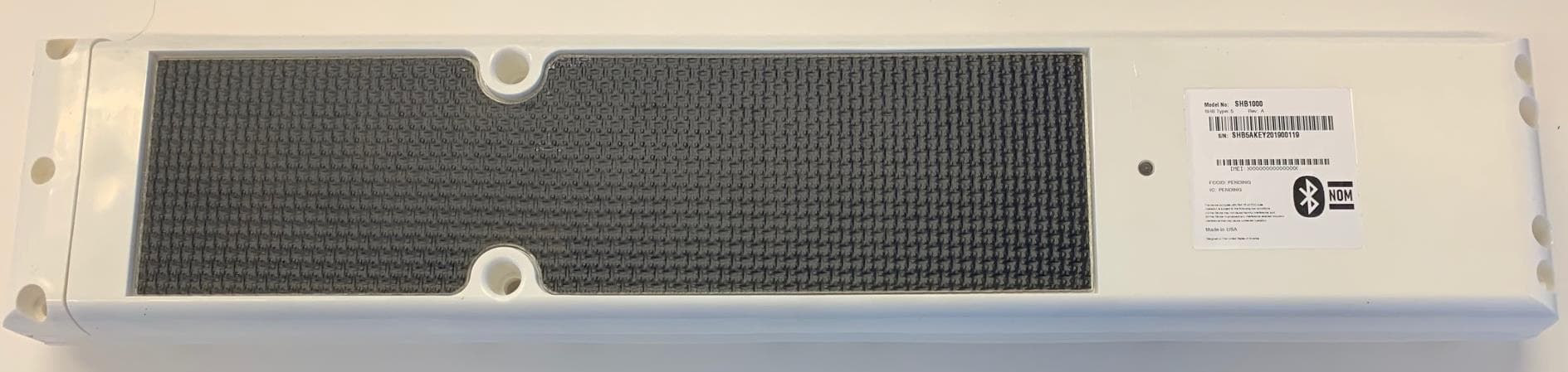
MTFSHB1000
Nov 12, 2020SkyHub Wireless Telematics Hub
Equipment Class
PCB - PCS Licensed Transmitter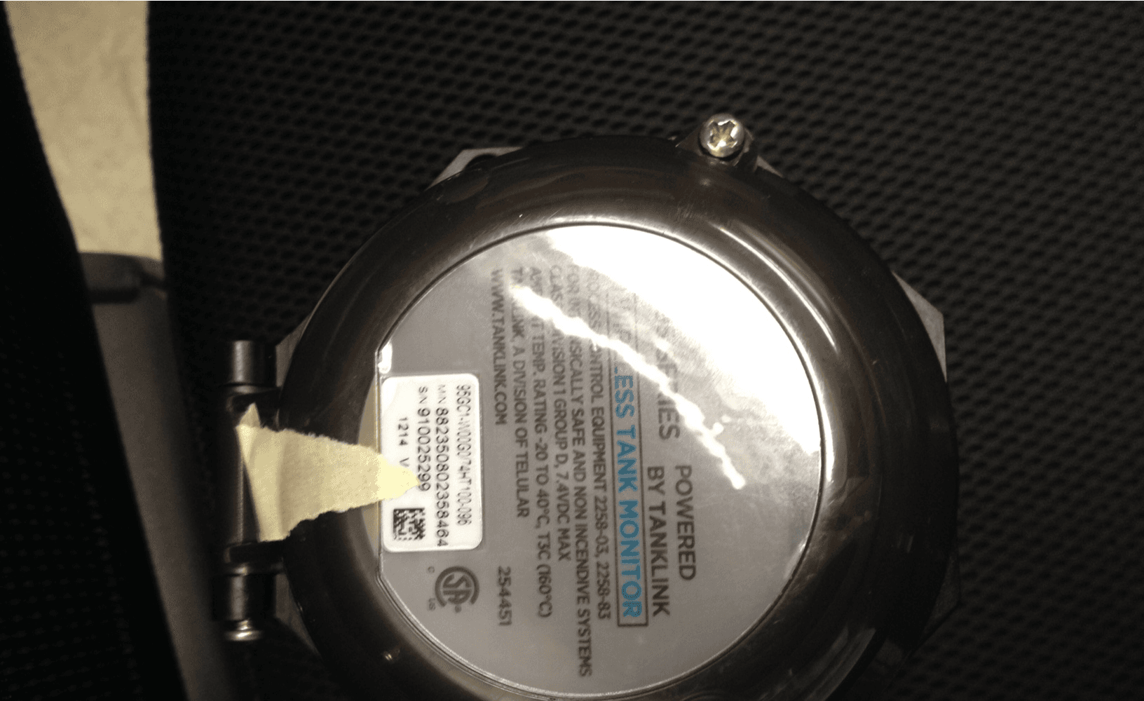
MTFTL9XC
Jan 03, 2016Wireless Tank Monitor Model TL9X, Client
Equipment Class
DTS - Digital Transmission System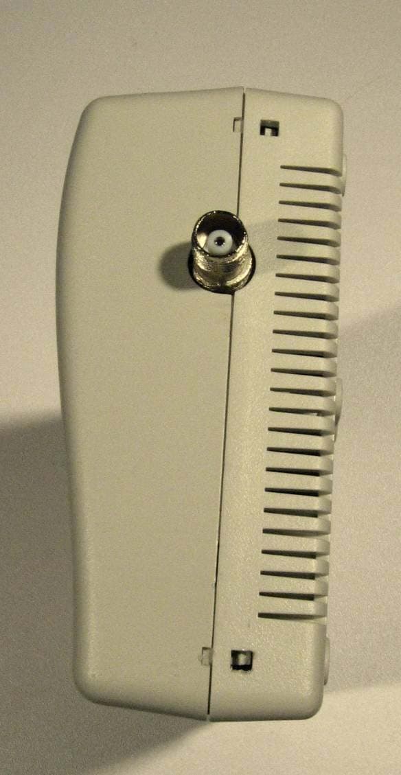
MTFTG5112597A
Nov 14, 2007Residential & Business Cellular Alarm Communicator
Equipment Class
PCB - PCS Licensed Transmitter