MVUDRC01Remote control transmitter
MotorGuide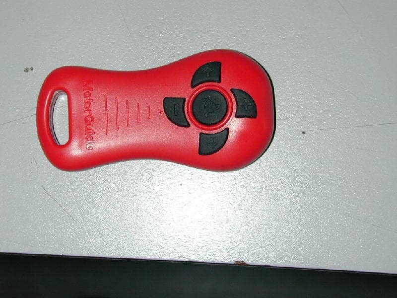
Click to zoom
Application Details
- Equipment Class
- DSC - Part 15 Security/Remote Control Transmitter
- Date of Grant
- May 26, 2005
- Application Purpose
- Original Equipment
- Date of Application
- May 26, 2005
- Equipment Note
- Remote control transmitter
- Frequency Range
- 915.00000000 - 915.00000000
- Company
- MotorGuide
- Country
- United States
Documents & Files
Document Text
Text extracted from the exhibit documents filed with the FCC. Open a document above to read the original.
Users Manual
Digital Remote DRC Owner’s Instruction Manual M887655 1 M887655 Thank you for purchasing this MotorGuide product! FCC Compliance Statement FCC ID No.: MVUDRC01 This device complies with part 15 of the FCC Rules. Operation is subject to the following two conditions: 1. This device may not cause harmful interference, and 2. This device must accept any interference received, including interference that may cause undesired o peration. WARNING: Modifications to this device not expressly approved by the manufacturer may invalidate the user’s right to operate this equipment". DRC INSTALLATION 1. Plug the receiver into the trolling motor foot- pedal cable. 2. Plug the foot-pedal into the receiver. 2 M887655 Note: The remote control system works with or without the foot pedal attached. PROGRAMMING THE SERIAL NUMBER Each remote unit has a unique serial number. Up to four serial numbers (remotes) can be stored by your receiver. For your remote to respond to your commands only and not those of other boaters, you must program the serial number into your receiver. Follow the instructions below (one time only) to program your receiver for each new remote: 1. Power the motor up - within 10 seconds, press and hold the + and - buttons on the remote simultaneously 2. Listen for a long high pitch beep 3. The receiver has now learned and stored the serial number of the remote. CONTROLLING THE BOAT REMOTELY 1. Steering: Press the left or right arrow buttons to steer the boat, a beep will sound 3 M887655 each time one of the arrow buttons is pressed. Each button press steers the motor left or right one step. Holding a button down will rapidly steer the motor until it reaches a stop; once it has reached a stop, the receiver will no longer beep when you press the button. When the motor is first powered-up, it automatically steers to a center position unless a foot-pedal is used, then it will steer to the position of the pedal. 2. Speed: Use the + and – buttons to control the speed of the motor, a beep will sound each time the + or – buttons are pushed. Holding the button down will rapidly speed- up or slow-down the motor until it reaches minimum or maximum speed; once at the limit, the receiver will no longer beep when you press a button. When the motor is first powered-up, the initial speed is set to the same setting as on the foot-pedal speed wheel. If a foot-pedal is 4 M887655 not used, the initial speed is equivalent to a setting of 2 ½ on the foot-pedal. 3. Prop On/Off – turn the prop on or off by pressing the center button and it will alternate between on and off. The “on” condition is indicated by a high- pitched beep while “off” is indicated by a low-pitched beep. USING THE REMOTE WITH A FOOT- PEDAL 1. For maximum flexibility, the remote can be used in combination with the foot-pedal. Please note the following when doing so: 2. The last controller device (foot-pedal or remote) to send a command will be in control. 3. When going from foot-pedal to remote control, the speed and steering will always start at the last foot-pedal setting, but will end up wherever the operator sets the remote. 4. When going from remote to foot-pedal control, the motor will immediately: 5 M887655 steer to the current setting of the pedal and adapt to the speed setting on the speed- wheel. CAUTION When changing from the remote to the foot-pedal, speed and steering will instantly convert to the foot- pedal setting. USING THE REMOTE WHILE TRACKING WITH A PTSv MOTOR Do not use the “Left” and “Right” arrow buttons on the remote while the motor is tracking. Use the following commands: 1. Tracking can be suspended with the “On/Off” button. 2. Once Tracking is suspended, use the left and right arrow buttons on the remote to steer. 3. To resume tracking, press the “Resume” button on the foot-pedal. 6 M887655 a) Motor speed can be changed at any time using the “+” and “-“buttons on the remote. REMOTE BATTERY REPLACEMENT Use only 3V lithium type CR2032 replacement batteries. Follow these instructions to change the battery: 1. Remove the four screws on the back of the remote control. 2. Remove the Remote Control’s back cover 3. Using a pencil, push the battery out of its holder. 4. With the “+” symbol facing up, slide the new battery in the holder. 5. Replace the cover and four screws. SPECIAL COMMANDS 1. Steer to Center – to automatically return to center, press and hold the steer left and right arrow buttons on the remote until a low pitch 7 M887655 beep sounds. The motor will then steer back to the center position. 2. Erase Memory - to erase all serial numbers stored in the receiver’s memory: Power-up the motor Within 10 seconds, press and hold all four outer buttons on the remote Listen for a long low pitch beep indicating the receiver has erased all stored serial numbers. FOR REPAIR SERVICE Contact your nearest MotorGuide Service Dealer. See a complete listing of Service Dealers in the US and Canada at our MotorGuide web site: www.motorguide.com. Call Mercury Marine Consumer Affairs to obtain the name and location of the Service Dealer nearest you. United States: 1-920-929-5040 8 M887655 TROUBLESHOOTING – Frequently Asked Questions The receiver beeps when I press a button on the remote but nothing happens. The receiver does not have the remotes serial number programmed; refer to “Programming the Serial Number”. Programming the serial number doesn’t work. The receiver’s memory might be full, see “Erasing Memory” then try programming the serial number again. Also, the serial number must be programmed within ten seconds of powering-up the motor. When I am standing at the back of the boat and I press a button on the remote, the receiver does not beep. Move the receiver away from potentially interfering devices and experiment with orienting the receiver in different directions 9 M887655 until you get good reception. Check the battery in the remote as well. When I press a button nothing happens but the foot pedal still works. If the receive…
Text truncated - open the document above for the full version.
Operational Description
OPERATIONAL DESCRIPTION FCC ID. MVUDRC01 Frequency of operation: 915 MHz Radio Chip: Infineon TDA 5102 Crystal Frequency: 7.1505 MHz Frequency tolerance: +/- 20 ppm –10 deg. C to +70 deg. C The DRC 01 Digital Remote Control Transmitter is used to control direction and speed of the motor in a fishing boat. It is used with the model M887651 receiver/controller. The radio transmitter is based on the Infineon TDA 5102 radio chip. An integral loop antenna is etched on the PCB.
Test Report
NEMKO Test Report: 4L0547RUS1Rev1 Applicant: Motorguide 835 West 41 st Street Tulsa, OK 74107 Equipment Under Test: DRC01 Remote Control Transmitter (E.U.T.) FCC ID: MVUDRC01 In Accordance With: FCC Part 15, Subpart C For Low Power Transmitters Operating Periodically In The Band 40.66 - 40.77 MHz And Above 70 MHz Tested By: Nemko USA, Inc. 802 N. Kealy Lewisville, TX 75057-3136 Authorized By: Tom Tidwell, RF Group Manager Date: 25 May, 2005 Total Number of Pages: 19 Nemko USA, Inc. FCC PART 15, SUBPART C POWER TRANSMITTERS EQUIPMENT: DRC01 FCC ID.: MVUDRC01 PROJECT NO.: 4L0547RUS1Rev1 Page 2 of 19 TABLE OF CONTENTS Section 1. Summary of Test Results ..................................................................................... 3 Section 2. Equipment Under Test (E.U.T.) ........................................................................... 5 Section 3. Equipment Configuration ..................................................................................... 8 Section 4. Transmission Requirements ................................................................................. 9 Section 5. Radiated Emissions ............................................................................................ 11 Section 6. Occupied Bandwidth .......................................................................................... 14 Section 7. Block Diagrams ................................................................................................... 15 Section 8. Test Equipment List ........................................................................................... 18 Nemko USA, Inc. FCC PART 15, SUBPART C POWER TRANSMITTERS EQUIPMENT: DRC01 FCC ID.: MVUDRC01 PROJECT NO.: 4L0547RUS1Rev1 Page 3 of 19 Section 1. Summary of Test Results Manufacturer: Model No.: Sample No. Serial No. Date Received Modification Status 001 None 10/14/04 01550, Rev. B N/A - Not modified from original state General: All measurements are traceable to national standards. These tests were conducted on a sample of the equipment for the purpose of demonstrating compliance with Part 15, Subpart C, Paragraph 15.231. All tests were conducted using measurement procedure ANSI C63.4-1992. Radiated emissions are made on an open area test site. A description of the test facility is on file with the FCC. New Submission Production Unit Class II Permissive Change Pre-Production Unit THIS TEST REPORT RELATES ONLY TO THE ITEM(S) TESTED. THE FOLLOWING DEVIATIONS FROM, ADDITIONS TO, OR EXCLUSIONS FROM THE TEST SPECIFICATIONS HAVE BEEN MADE. See “ Summary of Test Data”. NVLAP LAB CODE: 100426-0 Nemko USA Inc. authorizes the above named company to reproduce this report provided it is reproduced in its entirety and for use by the company’s employees only. Any use which a third party makes of this report, or any reliance on or decisions to be made based on it, are the responsibility of such third parties. Nemko USA Inc. accepts no responsibility for damages, if any, suffered by any third party as a result of decisions made or actions based on this report. This report applies only to the items tested. Nemko USA, Inc. FCC PART 15, SUBPART C POWER TRANSMITTERS EQUIPMENT: DRC01 FCC ID.: MVUDRC01 PROJECT NO.: 4L0547RUS1Rev1 Page 4 of 19 Summary Of Test Data Name of Test Paragraph No. Results Transmission Requirements 15.231(a) Complies Radiated Emissions 15.231(b) Complies Occupied Bandwidth 15.231(c) Complies Frequency Tolerance 15.231(d) N/A Alternate Field Strength Requirements 15.231(e) N/A Powerline Conducted Emissions 15.207 N/A Footnotes: This device operates with battery only. Nemko USA, Inc. FCC PART 15, SUBPART C POWER TRANSMITTERS EQUIPMENT: DRC01 FCC ID.: MVUDRC01 PROJECT NO.: 4L0547RUS1Rev1 Page 5 of 19 Section 2. Equipment Under Test (E.U.T.) General Equipment Information Frequency Range: 915 MHz (fixed) Operating Frequency(ies) of Sample: 915 MHz Type of Emission: L1D Emission Designator: 396KL1D Supply Power Requirement: 3Vdc 20 mm Lithium coin cell Duty Cycle Correction Factor: -0.98 dB Nemko USA, Inc. FCC PART 15, SUBPART C POWER TRANSMITTERS EQUIPMENT: DRC01 FCC ID.: MVUDRC01 PROJECT NO.: 4L0547RUS1Rev1 Page 6 of 19 Description of E.U.T. The EUT is a momentarily operated keychain radio transmitter. The transmitter is used to control a boat motor. Nemko USA, Inc. FCC PART 15, SUBPART C POWER TRANSMITTERS EQUIPMENT: DRC01 FCC ID.: MVUDRC01 PROJECT NO.: 4L0547RUS1Rev1 Page 7 of 19 Justification The E.U.T. was configured for testing as per typical installation. The following combinations were investigated to establish worst case configuration: (1) Oriented in three orthogonal axis. (2) Continuous transmit. Nemko USA, Inc. FCC PART 15, SUBPART C POWER TRANSMITTERS EQUIPMENT: DRC01 FCC ID.: MVUDRC01 PROJECT NO.: 4L0547RUS1Rev1 Page 8 of 19 Section 3. Equipment Configuration The device was mounted on a non-conductive stand. The device was tested in three orthogonal axis to determine worst-case orientation. Nemko USA, Inc. FCC PART 15, SUBPART C POWER TRANSMITTERS EQUIPMENT: DRC01 FCC ID.: MVUDRC01 PROJECT NO.: 4L0547RUS1Rev1 Page 9 of 19 Section 4. Transmission Requirements NAME OF TEST: Transmission Requirements PARA. NO.: 15.231(a) TESTED BY: David Light DATE: 10/14/04 Minimum Standard: 15.231(a) Continuous transmissions such as voice, video or data transmissions are not permitted. 15.231(a)(1) A manually operated transmitter shall employ a switch that will automatically deactivate the transmitter within not more than 5 seconds after being released. 15.231(a)(2) A transmitter activated automatically shall cease transmission within 5 seconds of activation. 15.231(a)(3) Periodic transmissions at regular pre- determined intervals are not permitted. However polling or supervisory transmissions to determine system integrity of transmitters used in security or safety applications are allowed if the periodic rate of transmission does not exceed one transmission of not more than one second duration per hour for each…
Text truncated - open the document above for the full version.
Contact Information
Applicant
Rich Mullennix(Test Lab Manager)
Technical Contact
Test Firm
Nemko Dallas, Inc.Michael Cantwell
Technical Specifications
| # | Rule Parts | Frequency Range | Power Output |
|---|---|---|---|
| 1 | 15.231 | 915 MHz - 915 MHz | - |
Other Applications from MotorGuide

MVU10148
Jan 22, 2014Wireless handheld remote key fob device for PINPOINT
Equipment Class
DXX - Part 15 Low Power Communication Device Transmitter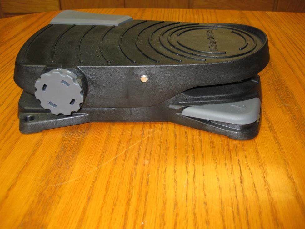
MVU09291
Dec 17, 2013Wireless foot activated remote device
Equipment Class
DXX - Part 15 Low Power Communication Device Transmitter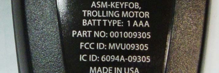
MVU09305
Dec 17, 2013Wireless handheld remote key fob device
Equipment Class
DXX - Part 15 Low Power Communication Device Transmitter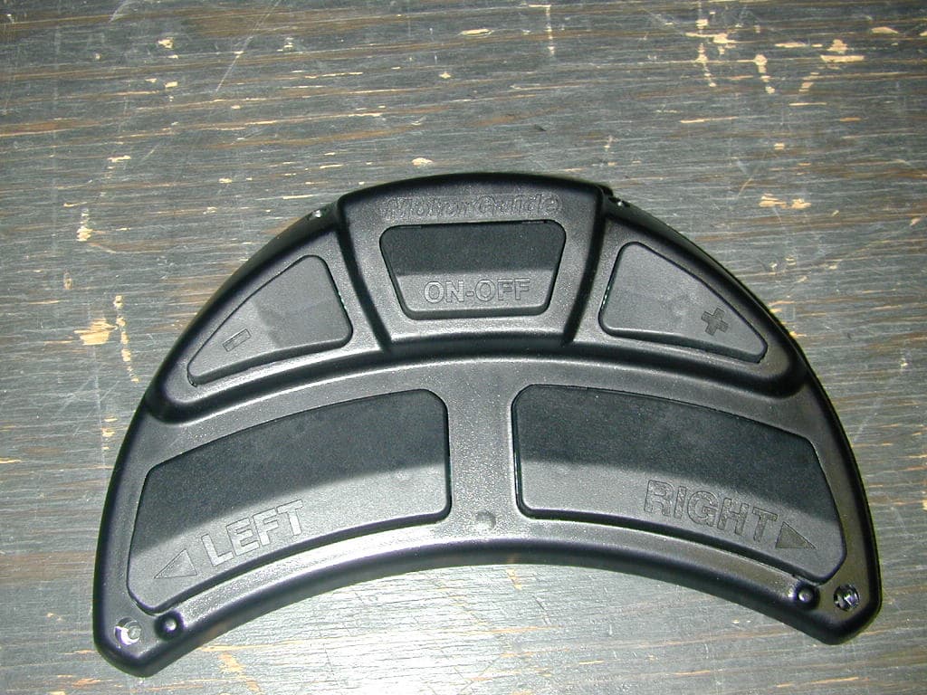
MVUFP02
Jan 09, 2006Remote Control Transmitter
Equipment Class
DXX - Part 15 Low Power Communication Device Transmitter
MVUFP01
Oct 12, 2005Remote Control Transmitter
Equipment Class
DXX - Part 15 Low Power Communication Device Transmitter