MVUFP02Remote Control Transmitter
MotorGuide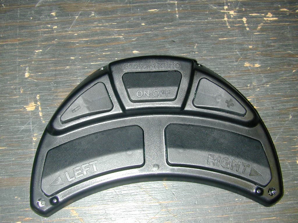
Click to zoom
Application Details
- Equipment Class
- DXX - Part 15 Low Power Communication Device Transmitter
- Date of Grant
- Jan 09, 2006
- Application Purpose
- Original Equipment
- Date of Application
- Jan 09, 2006
- Equipment Note
- Remote Control Transmitter
- Frequency Range
- 915.20000000 - 915.20000000
- Company
- MotorGuide
- Country
- United States
Documents & Files
Document Text
Text extracted from the exhibit documents filed with the FCC. Open a document above to read the original.
Users Manual
835 W. 41 st Street Tulsa, Oklahoma 74107 www.motorguide.com © 2005, MotorGuide FCC and IC Compliance Statement FCC ID #MVUFP01, MVUFP02 IC ID 6094A-FP01, 6094A-FP02 This device complies with part 15 of the FCC Rules. Operation is subject to the following two conditions: 1. This device may not cause harmful interference, and 2. This device must accept any interference received, including interference that may cause undesired operation. This device complies with FCC Rules. Changes or modifications not expressly approved by MotorGuide could void the user's authority to operate the equipment. Congratulations ... on your purchase of the MotorGuide Wireless Trolling Motor. This motor has been designed, engineered, and manufactured to give you the best possible dependability and exceptional performance for years of enjoyment. These features offer an unrivaled fishing experience: Durability Oversized brushes for efficient and dependable power Fully Remote Operation Integrated, Quick Release Mount Modular Digital Electronics Three-year Limited Warranty IMPORTANT!! REGISTER YOUR PRODUCT The warranty registration card (located inside the box) should be completed and mailed to MotorGuide to validate your warranty. WARRANTY CARD REGISTRATION IS INCLUDED IN THE BOX AND IS SEPARATE FROM THIS MANUAL. PLEASE FILL OUT IMMEDIATELY AND MAIL TO VALIDATE YOUR WARRANTY. At MotorGuide, we’ve taken all the victories, failures, blood, sweat, tears, hours, days and years to heart and built what are possibly the best performing, most reliable trolling motors ever. It’s a result of re-engineering from top to bottom, from our new digital modules, to new switches and props. Why? The reason is simple. To give you the advantage—and, in this case it’s a digital advantage. Because at MotorGuide, we believe there are some things you should Never Stop doin g, NEVER STOP LEARNING, NEVER STOP IMPROVING, AND NEVER EVER STOP FISHING. TABLE OF CONTENTS GENERAL INFORMATION....................................................................2 Safety DO’s and DON’Ts ...................................................................3 Operating Safety................................................................................4 NOTES:..................................................................................................5 FEATURES.............................................................................................6 Remote Capabilities ...........................................................................6 COMPONENTS......................................................................................7 Wireless Remote Foot-Pedal.............................................................7 Lower Unit..........................................................................................7 Column...............................................................................................7 Top Housing.......................................................................................7 Cradle Lock™ Mount.........................................................................8 Battery Indicator.................................................................................8 INSTALLATION....................................................................................10 Mount Installation.............................................................................10 Wiring & Battery Information............................................................13 Wire & Cable Routing..................................................................13 Establishing a Common Ground..................................................14 Recommendations.......................................................................14 Activating the Foot-Pedal Electronic ID...........................................17 Erasing the Receiver’s Memory.......................................................17 MOTOR & MOUNT OPERATION........................................................18 General Information Features & Components Installation Motor & Mount Operation Adjusting the Motor Depth and Deploying the Motor.......................18 Stowing the Motor............................................................................19 Operating the Foot-Pedal.................................................................20 MAINTENANCE...................................................................................21 Foot-Pedal Battery Replacement.....................................................21 Care & Cleaning Instructions...........................................................22 Customer Responsibilities................................................................22 Battery..........................................................................................22 Freezing Temperature Storage....................................................23 Installing or Replacing the Propeller ................................................23 TROUBLESHOOTING.........................................................................25 Frequently Asked Questions............................................................25 MOTORGUIDE ACCESSORIES 28 Troubleshooting & Accessories Warranty Maintenance MOTORGUIDE LIMITED THREE-YEAR WARRANTY.......................29 MOTORGUIDE WIRELESS 90-MM5997 For Questions, Contact Consumer Affairs at #1-920-929-5040 1 © 2005, MotorGuide www.motorguide.com NOTES: ____________________________________________________ ____________________________________________________ ____________________________________________________ ____________________________________________________ ____________________________________________________ ____________________________________________________ ____________________________________________________ ____________________________________________________ ____________________________________________________ ____________________________________________________ _________________…
Text truncated - open the document above for the full version.
Operational Description
TheoryofOperation ;***************************** THEORY OF OPERATION ********************************** ; ;THE MICRO BASICALLY OPERATES OUT OF SLEEP MODE, BEING WOKEN UP BY PIN CHANGE ;ON I/O RB0, RB1, RB3,AND RB4 AS A RESULT OF THE USER PRESSING A KEY. ;SINCE THERE IS NO POWER SWITCH THE MICRO ALWAYS HAS POWER APPLIED. IT EXECUTES ;A POR ONLY THE FIRST TIME THE BATTERY IS INSTALLED AND THEREAFTER EXECUTES CODE ;BASED ON WAKE UP ON PIN CHANGE RESET BY TESTING THE RBWUF FLAG.THE TRANSMITTER ;CHIP IS ALWAYS POWERED DOWN UNTIL A PACKET NEEDS TO BE SENT VIA THE PA ENABLE PIN. ; ;ONCE WOKEN UP THE KEYS ARE READ AND CHECKED FOR VALIDITY THEN THE DATA PACKET IS ;CONSTRUCTED. AFTER POWER IS APPLIED TO THE TRANSMITTER (ENABLE THE POWER AMP) AND THE WARM UP ;TIME HAS ELAPSED TO STABILIZE THE OSCILLATOR, THE DATA IS MANCHESTER ENCODED AND ;BIT BANGED OUT TO THE TRANSMITTERS FSK INPUT PIN. ;THE TRANSMITTER CHIP IS THEN DISABLED TO CONSERVE POWER AND THE SLEEP COMMAND EXECUTED. ;ON MULTIPLE KEY PRESSES THE UNIT WILL BE IMEDIATELY WOKEN BACK UP.BACK TO BACK PACKETS ARE ;SENT OUT EVERY 100mSEC.THE TRANSMITTER IS ALWAYS POWERED DOWN IN BETWEEN PACKETS. ;SINCE THERE IS NO TIMER INTERUPT AND THE WATCH DOG TIMMER HAS A MINIMUM FIXED TIMEOUT ;OF 18mSEC MULTIPLIED BY THE POST-SCALER, THE TIMER COUNTER HAS TO BE POLLED TO CALCULATE ;THE BIT RATE TIMES FOR THE MANCHESTER DATA STREAM. THE SYMBOL RATE IS 7.14Khz AND THE DATA ;is 3.57KHZ. ; ;THE SINGLE CHIP TRANSMITTER IS CONFIGURED FOR FSK MODULATION WITH A CENTER TRANSMIT FREQUENCY ;OF 915.2MHZ WITH FSK DEVIATIONS OF +/- 60KHZ.FSK MODULATION OCCURS BY SWITCHING CAPACITORS IN ;AND OUT OF THE CRYSTAL CIRCUIT THEREBY PULLING ITS FREQUENCY ONE WAY OR ANOTHER. ;TWO CAPACITORS ARE USED FOR EACH LEG TO FINE TUNE THE VALUE AND OBTAIN BETTER ;TOLERANCE. ;FOR FSK LOW THE SWITCH IS IN THE CLOSED POSITION SHUNTING HALF OF THE CAPACITORS ;TO GROUND.IN THIS CONDITION CAPACITANCE IS AT ITS HIGHEST VALUE AND THE CRYSTAL FREQUENCY ;IS AT ITS LOWEST. FOR FSK HIGH THE SWITCH IS IN THE OPEN POSITION, NOW ALL FOUR ;CAPACITORS ARE IN SERIES DROPING THE CAPACITANCE TO ITS LOWEST VALUE AND DRIVING ;THE FREQUENCY HIGH. ;THE CRYSTAL FUNDAMENTAL FREQUECNY OF 7.150MHZ IS DIVIDED BY 128 TO OBTAIN A FINAL OUTPUT ;NOMINAL FREQUENCY OF 915.2MHZ WHICH IS FINE TUNED BY THE CAPACITORS TO OBTAINF THE FSK DEVIATION. ;THE INTEGRAL POWER AMP IS OF A OPEN COLLECTOR CONFIGUATION SO IS BIASED THROUGH A ;INDUCTOR FILTER CAP COMBO PULLED HIGH TO THE BATTERY VOLTAGE OF 3.3V. ;THE OUTPUT IS LOW PASS FILTERED AND IMPEDANCE MATCHED TO 50 OHMS, CAPACITANCE IN SERIES ;BLOCKS BATTERY VOLTAGE FROM THE REST OF THE CIRCUITRY THAT FOLLOWS. ;ONCE IMPEDANCE MATCHED TO 50 OHMS, THE SIGNAL PASSES THROUGH A 50 OHM T-ATTENUATION PAD ;TO FINE TUNE THE FINAL POWER OUTPUT LEVEL. THE OUTPUT OF THE ATTENUATION PAD IS CONNECTED ;TO A 50 OHM 1/4 WAVE HELICAL ANTENNA THROUGH A 50 OHM MICROSTRIP TRACE. ;NETWORK ANALYZER TESTS SHOW A GOOD MATCH BETWEEN ANTENNA AND ATTENUATION PAD WITH A VSWR OF ;1.2 LOOKING BACK INTO THE CIRCUIT WITH A 50 OHM LOAD. Page 1
Test Report
Nemko Test Report: 5L0557RUS1 Applicant: MotorGuide Equipment Under Test: Transmitter MVP300022 (E.U.T.) In Accordance With: FCC Part 15, Subpart C, 15.249 Transmitters Tested By: Nemko USA Inc. 802 N. Kealy Lewisville, Texas 75057-3136 Authorized By: David Light, Wireless Engineer Date: 14 November 2005 Nemko USA FCC PART 15, SUBPART C TRANSMITTERS PROJECT NO.:5L0557RUS1 EQUIPMENT: Transmitter MVP300022 Page 2 of14 Table Of Contents Section 1. Summary Of Test Results ................................................................ 3 Section 2. General Equipment Specification ..................................................... 5 Section 3. Radiated Emissions.......................................................................... 7 Section 4.Test Equipment List........................................................................... 11 ANNEX A TEST DIAGRAMS ........................................................................... 12 Nemko USA FCC PART 15, SUBPART C TRANSMITTERS PROJECT NO.:5L0557RUS1 EQUIPMENT: Transmitter MVP300022 Page 3 of14 Section 1. Summary Of Test Results Manufacturer: MotorGuide Model No.: Transmitter MVP300022 Serial No.: None General: All measurements are traceable to national standards. These tests were conducted on a sample of the equipment for the purpose of demonstrating compliance with FCC Part 15.249. All tests were conducted using measurement procedure ANSI C63.4-2003. Radiated Emissions were made on an open area test site. New Submission Production Unit Class II Permissive Change Pre-Production Unit THIS TEST REPORT RELATES ONLY TO THE ITEM(S) TESTED. THE FOLLOWING DEVIATIONS FROM, ADDITIONS TO, OR EXCLUSIONS FROM THE TEST SPECIFICATIONS HAVE BEEN MADE. See “ Summary of Test Data”. NVLAP LAB CODE: 100426-0 Nemko USA Inc. authorizes the above named company to reproduce this report provided it is reproduced in its entirety and for use by the company’s employees only. Any use which a third party makes of this report, or any reliance on or decisions to be made based on it, are the responsibility of such third parties. Nemko USA Inc. accepts no responsibility for damages, if any, suffered by any third party as a result of decisions made or actions based on this report. This report applies only to the items tested. Nemko USA FCC PART 15, SUBPART C TRANSMITTERS PROJECT NO.:5L0557RUS1 EQUIPMENT: Transmitter MVP300022 Page 4 of14 Summary Of Test Data NAME OF TEST PARA. NO. RESULT Conducted Emissions 15.207 Not Applicable Radiated Emissions 15.249 Complies Footnotes For N/A’s: This device is battery powered. Testing was performed using a fully charged battery. Nemko USA FCC PART 15, SUBPART C TRANSMITTERS PROJECT NO.:5L0557RUS1 EQUIPMENT: Transmitter MVP300022 Page 5 of14 Section 2. General Equipment Specification Frequency Range: Single Operating Frequency(ies) of Sample: 915.2 MHz Tunable Bands: N/A User Frequency Adjustment: Dip Switches Integral Antenna Yes No Nemko USA FCC PART 15, SUBPART C TRANSMITTERS PROJECT NO.:5L0557RUS1 EQUIPMENT: Transmitter MVP300022 Page 6 of14 Description of Device Tested Remote control for trolling motor. System Diagram Nemko USA FCC PART 15, SUBPART C TRANSMITTERS PROJECT NO.:5L0557RUS1 EQUIPMENT: Transmitter MVP300022 Page 7 of14 Section 3. Radiated Emissions NAME OF TEST: Radiated Emissions PARA. NO.: 15.249 TESTED BY: Kevin Rose DATE: 11/02/2005 Minimum Standard: Para no. 15.249 (a) The field strengths shall not exceed the following: Fundamental (MHz) Field Strength (mV/m) Field Strength (dBμV) Harmonic (mV/m) Harmonic (dBμV) 902-928 50 94 0.5 54 2400-2483.5 50 94 0.5 54 (b) Field strength limits are specified at a distance of 3 metres. (c) Emissions radiated outside of the specified frequency bands, except for harmonics, shall be attenuated by at least 50 dB below the level of the fundamental or to the general radiated limits of 15.209 whichever is the less attenuation. (d) ...for frequencies above 1000 MHz, the above field strength limits are based on average limits. However, the peak field strength of any emission shall not exceed the maximum permitted average limits specified above by more than 20 dB under any condition of modulation. Test Results: Complies Measurement Data: See attached table. Test Equipment Used: 759-791-1484-1485-1464-1016-993-760 Test Equipment Settings: RBW=1 MHz, VBW=1 MHz Nemko USA FCC PART 15, SUBPART C TRANSMITTERS PROJECT NO.:5L0557RUS1 EQUIPMENT: Transmitter MVP300022 Page 8 of14 Test Data - Radiated Emissions Meas. Ant. Atten. Meter Antenna Path RF Corrected Spec. CR/SL Pass Freq. Pol. Reading Factor Loss Gain Reading limit Diff. Fail (MHz) (H/V) (dB) (dBuV) (dB) (dB) (dB) (dBuV/m) (dBuV/m) (dB) Unc. 915.2 H 0 57.6 23.4 8.2 0.0 89.2 94.0 -4.8 Pass 915.2 V 0 51.2 23.4 8.2 0.0 82.8 94.0 -11.2 Pass Harmonics Frequency (MHz) SPECTRUM ANALYZER READING EQUIPMENT CORRECTION FACTORS CORRECTED READINGS. SPEC MARGIN PEAK/ AVG POL 1,830.50 48.2 -2.146.154-7.9 Peak Horiz 1,830.50 46.8 -2.144.754-9.3 Peak Vert Spectrum was searched from 30 MHz to 9200 MHz. All emissions within 20 dB of the specification limit of 54 dBμV/m are reported. Nemko USA FCC PART 15, SUBPART C TRANSMITTERS PROJECT NO.:5L0557RUS1 EQUIPMENT: Transmitter MVP300022 Page 9 of14 20 dB Bandwidth Nemko USA FCC PART 15, SUBPART C TRANSMITTERS PROJECT NO.:5L0557RUS1 EQUIPMENT: Transmitter MVP300022 Page 10 of14 Radiated Photographs Nemko USA FCC PART 15, SUBPART C TRANSMITTERS PROJECT NO.:5L0557RUS1 EQUIPMENT: Transmitter MVP300022 Page 11 of14 Section 4. Test Equipment List Manufacturer Model Number A.H. SYSTEMS SAS-200/510 Storm PR90-010-072 Storm PR90-010-216 A.H. Systems SAS-200/571 HEWLETT PACKARD 8449A ICC LNA25 Hewlett Packard 8563E Electro Metrics MFC-25 01/14/05 01/15/07 11/12/05PREAMP, 25dB 11/12/04 Pre-Amp 01/08/02 01/09/04 11/12/0511/12/04 791 1464 Cable 2.0-18.0 Ghz N/A Horn antenna XXX 2749A00159 398 3551A04428 Spectrum analyzer Calibration Due 1485 993 1016 08/02/05 08/02/06 Nemko ID Description Serial Number Calibratio…
Text truncated - open the document above for the full version.
Contact Information
Applicant
Rich Mullennix(Test Lab Manager)
Technical Contact
Non-Technical Contact
Nemko USATom Tidwell
[email protected]972 436 9600
Test Firm
Nemko Dallas, Inc.Michael Cantwell
Technical Specifications
| # | Rule Parts | Frequency Range | Power Output |
|---|---|---|---|
| 1 | 15C | 915.2 MHz - 915.2 MHz | - |
Other Applications from MotorGuide

MVU10148
Jan 22, 2014Wireless handheld remote key fob device for PINPOINT
Equipment Class
DXX - Part 15 Low Power Communication Device Transmitter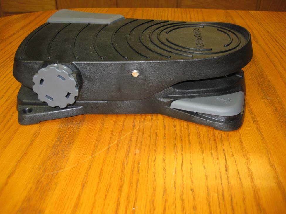
MVU09291
Dec 17, 2013Wireless foot activated remote device
Equipment Class
DXX - Part 15 Low Power Communication Device Transmitter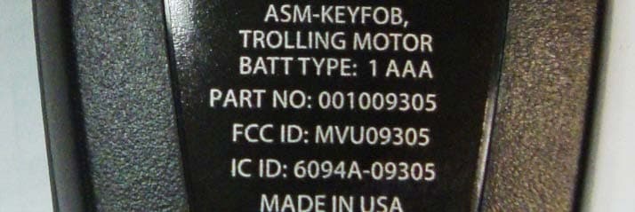
MVU09305
Dec 17, 2013Wireless handheld remote key fob device
Equipment Class
DXX - Part 15 Low Power Communication Device Transmitter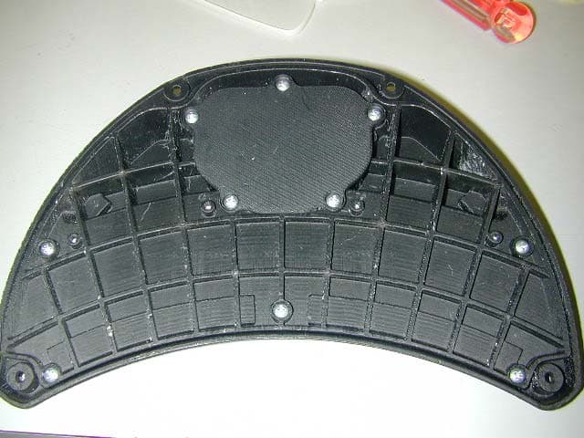
MVUFP01
Oct 12, 2005Remote Control Transmitter
Equipment Class
DXX - Part 15 Low Power Communication Device Transmitter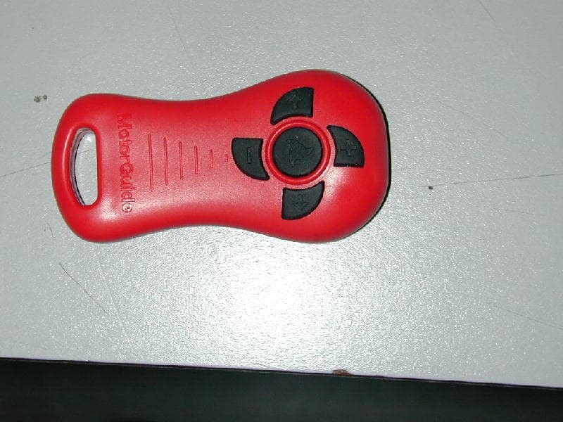
MVUDRC01
May 26, 2005Remote control transmitter
Equipment Class
DSC - Part 15 Security/Remote Control Transmitter