N3ETRILINK70163RF Toy
Wild Planet Entertainment, Inc.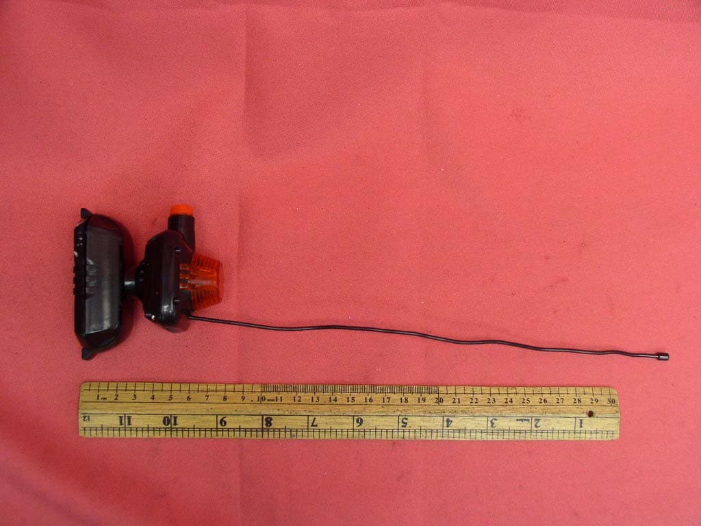
Click to zoom
Application Details
- Equipment Class
- DXX - Part 15 Low Power Communication Device Transmitter
- Date of Grant
- Apr 19, 2007
- Application Purpose
- Original Equipment
- Date of Application
- Apr 19, 2007
- Equipment Note
- RF Toy
- Frequency Range
- 49.86000000 - 49.86000000
- Country
- United States
Documents & Files
Document Text
Text extracted from the exhibit documents filed with the FCC. Open a document above to read the original.
Users Manual
HOW IT WORKS ALARM #1 has a motion sensor and a light & sound alarm. This alarm also “arms” the other two alarms via wireless signals. ALARM #2 has a motion sensor, a targeting lazer and a loud alarm siren. This alarm “sleeps” until armed by #1. It will not operate until #1 has been set off. ALARM #3 has a motion sensor and a dual dart launcher. This alarm also “sleeps” until armed by #1. It will not operate until #1 has been set off. This unique wireless link system protects your valuables against enemy spies. If someone enters your room, the alarms won’t go off unless they mess with your stuff and trigger Alarm #1. They can get in, but they can’t get out! SETTING UP THE ALARMS Fully extend the ANTENNAS on all 3 alarms. Antennas should be pointing straight up for best results. 1. Set Alarm #1 by placing it on the object you want to protect. Or, aim it with the LENS pointing at the objects or area you want to protect. When movement is detected, flashing light & sound will go off and other two alarms will be armed by wireless signal. 2. Place Alarm #2 to stun the intruder with its loud siren as he tries to leave. Point the LENS across the path he will take. After it is armed, the TARGETING LAZER will be activated and you will see a red spot on the wall in the direction where it is pointed. 3. Insert a DART into each LAUNCH PORT on Alarm #3 until it locks into place. Aim LENS across the path the intruder is likely to take when fleeing the scene after other alarms go off. Swivel launcher and tilt up or down to aim darts. Do not aim at face level. 4. Turn on POWER SWITCHES of Alarms #2 and #3 first, and Alarm #1 last. Alarm #1 has a built-in delay of a few seconds so you can safely exit the room without setting the system off. Ages 6 and Up 70163 Requires 7 AAA (LR03) batteries, not included. Important: Please save this instruction sheet. It contains valuable product information. TM TRI-LINK ALARM SYSTEM 70163-4000 PR 3/07 IF YOU HAVE ANY QUESTIONS, PLEASE CONTACT US AT 1-800-247-6570 WWW.WILDPLANET.COM/HELP Wild Planet Entertainment, Inc., P.O. Box 194087 San Francisco, CA 94119-4087 TM © 2006 Wild Planet Entertainment, Inc., San Francisco, CA 94104, USA. All rights reserved. PRINTED IN CHINA. Product colors and specifications subject to change. Tri-Link Alarm System 3 Linked Hi-Tech Alarms TM ADULTS: INSTALLING BATTERIES 1. Locate battery door on bottom of each alarm. 2. Use small Philips screwdriver to loosen screw, remove battery door. 3. Install 3 AAA (LR03) batteries in dart launcher, 2 AAA (LR03) batteries in each of other two alarms. 4. Replace doors, tighten screws. Important: Observe battery polarity (direction, + and – ) BATTERY SAFETY 1. Only adults should install and replace batteries. 2. Do not recharge non-rechargeable batteries. 3. Remove dead or exhausted batteries. 4. Insert batteries correctly. Match positive and negative signs. 5. The supply terminals are not to be short circuited. 6. Do not use rechargeable batteries. 7. Do not mix alkaline, standard (carbon-zinc), or rechargeable (nickel-cadmium) batteries. 8. Do not mix old and new batteries. 9. Only the batteries of the same or equivalent type recommended to be used. 10. Do not dispose of batteries in a fire; they may explode. 11. Dispose of batteries safely. Alarms #1 and #2Dart launcher #1 MOTION SENSOR#2 LAZER SIREN#3 DART LAUNCHER Tip: As the intruder passes Alarm #3, there is a short delay before the darts fire. Swivel and tilt the launcher so that the darts will launch ahead of the intruder. You can test this yourself to see how far you need to “lead” your target in this way. CAUTION: Do not aim at eyes or face. To avoid injury: use only darts designed for this product. Do not modify darts or launcher. WARNING: Changes or modifications to this unit not expressly approved by the party responsible for compliance could void the user’s authority to operate the equipment. FCC ID N3ETRILINK70163 This device complies with Part 15 of the FCC Rules. Operation is subject to the following two conditions: (1) This device may not cause harmful interference, and (2) This device must accept any interference received, including interference that may cause undesired operation. Power switch OFF / ON Pull out grooved ring around Lenses to narrow each sensor’s field and make it less sensitive to movement. Push in to widen sensor’s field and make it more sensitive. Swivel base Power switch ON/OFF Load darts into launch ports Lens ON/OFF Power switch Swivel (side-to-side) Tilt (up/down) Antenna Antenna Antenna Targeting lazer Flashing light TROUBLESHOOTING • If alarms fail to go off, check that nothing is block- ing the sensor lenses. The sensor will best detect movement five feet directly in front of the lens. • Direct sunlight may set off the alarms. Don’t face alarms into very bright light. Also, pulling out grooved rings will reduce their sensitivity to light. • Make sure all three antennas are fully extended and pointing straight up. • Remember, Alarms #2 and #3 will not go off unless Alarm #1 has been set off first. • If alarms still do not go off, replace batteries. CUSTOMIZE YOUR SYSTEM! Alarms #2 and #3 are interchangeable. You can place the Lazer Siren last to stop ’em in their tracks until you get there to make the bust! NOTE: This equipment has been tested and found to comply with the limits for a Class B digital device, pursuant to Part 15 of the FCC Rules. These limits are designed to provide reasonable protection against harmful interference in a residential installation. This equipment generates, uses and can radiate radio frequency energy and, if not installed and used in accordance with the instructions, may cause harmful interference to radio communications. However, there is no guarantee that interference will not occur in a particular installation. If this equipment does cause harmful interference to radio or television reception, which can be determined by turning the equipment off and on, the user is encouraged…
Text truncated - open the document above for the full version.
External Photos
FCC ID: N3ETRILINK70163 Ophoto1 Ophoto2 FCC ID: N3ETRILINK70163 Ophoto3 Ophoto4 FCC ID: N3ETRILINK70163 Ophoto5
Internal Photos
FCC ID: N3ETRILINK70163 Iphoto1 Iphoto2 FCC ID: N3ETRILINK70163 Iphoto3 Iphoto4 FCC ID: N3ETRILINK70163 Iphoto5
Operational Description
FCC ID: N3ETRILINK70163 Technical Description : The brief circuit description is listed as follows : - X1, Q4, T1 and associated circuit act as 49.860 MHz Oscillator and Modulator. - U2 ATS302T acts as Encoder. - U1 SXC1122VB002 acts as MCU. - Q1, Q2, Q3 and associated circuit act as Signal Amplifier. - PH1 EL-3PTWC-B1 acts as Light Sensor. Antenna Used : An integral antenna (non-extendable) has been used.
Test Report
• The test results reported in this report shall refer only to the sample actually tested and shall not refer or be deemed to refer to bulk from which such a sample may be said to have been obtained. • This report shall not be reproduced except in full without prior authorization from Intertek Testing Services Hong Kong Limited. • The evaluation data of the report will be kept for 3 years from the date of issuance. FCC ID : N3ETRILINK70163 Wild Planet Entertainment Inc. Application For Certification (FCC ID: N3ETRILINK70163) Transmitter Sample Description : Tri-Link Alarm System Model : 70163 We hereby certify that the sample of the above item is considered to comply with the requirements of FCC Part 15, Subpart C for Intentional Radiator, mention 47 CFR [4-5-2005] 0705866 AC/at April 20, 2007 INTERTEK TESTING SERVICES FCC ID: N3ETRILINK70163 i LIST OF EXHIBITS INTRODUCTION EXHIBIT 1: General Description EXHIBIT 2: System Test Configuration EXHIBIT 3: Emission Results EXHIBIT 4: Equipment Photographs EXHIBIT 5: Product Labelling EXHIBIT 6: Technical Specifications EXHIBIT 7: Instruction Manual EXHIBIT 8: Miscellaneous Information INTERTEK TESTING SERVICES FCC ID: N3ETRILINK70163 ii MEASUREMENT/TECHNICAL REPORT Wild Planet Entertainment Inc. - MODEL: 70163 FCC ID: N3ETRILINK70163 April 20, 2007 This report concerns (check one:) Original Grant X Class II Change Equipment Type: Low Power Transmitter Deferred grant requested per 47 CFR 0.457(d)(1)(ii)? Yes No X If yes, defer until: date Company Name agrees to notify the Commission by: date of the intended date of announcement of the product so that the grant can be issued on that date. Transition Rules Request per 15.37? Yes No X If no, assumed Part 15, Subpart C for intentional radiator - the new 47 CFR [4-5- 2005 Edition] provision. Report prepared by: Chan Kar Ming, Anthony Intertek Testing Services 2/F., Garment Center, 576, Castle Peak Road, HONG KONG Phone: 852-2173-8517 Fax: 852-2742-9149 INTERTEK TESTING SERVICES FCC ID: N3ETRILINK70163 iii Table of Contents 1.0 General Description................................................................................................ 2 1.1 Product Description ............................................................................................. 2 1.2 Related Submittal(s) Grants................................................................................. 2 1.3 Test Methodology................................................................................................ 3 1.4 Test Facility ......................................................................................................... 3 2.0 System Test Configuration..................................................................................... 5 2.1 Justification.......................................................................................................... 5 2.2 EUT Exercising Software ..................................................................................... 5 2.3 Special Accessories............................................................................................. 5 2.4 Equipment Modification ....................................................................................... 6 2.5 Support Equipment List and Description .............................................................. 6 3.0 Emission Results .................................................................................................... 8 3.1 Field Strength Calculation .................................................................................... 9 3.1 Field Strength Calculation (cont’d) ..................................................................... 10 3.2 Radiated Emission Configuration Photograph .................................................... 11 3.3 Radiated Emission Data .................................................................................... 12 4.0 Equipment Photographs ....................................................................................... 16 5.0 Product Labelling .................................................................................................. 18 6.0 Technical Specifications....................................................................................... 20 7.0 Instruction Manual ................................................................................................ 22 8.0 Miscellaneous Information................................................................................... 24 8.1 Measured Bandwidth......................................................................................... 25 8.2 Discussion of Pulse Desensitization................................................................... 26 8.3 Calculation of Average Factor ............................................................................ 27 8.4 Emission Test Procedures ................................................................................ 28 8.4 Emission Test Procedures (Cont’d).................................................................... 29 INTERTEK TESTING SERVICES FCC ID: N3ETRILINK70163 iv List of attached file Exhibit type File Description filename Test Report Test Report report.pdf Operation Description Technical Description descri.pdf Test Setup Photo Radiated Emission radiated photos.doc Test Report Bandwidth Plot bw.pdf External Photo External Photo external photos.doc Internal Photo Internal Photo internal photos.doc Block Diagram Block Diagram block.pdf Schematics Circuit Diagram circuit.pdf ID Label/Location Label Artwork and Location label.pdf User Manual User Manual manual.pdf Test Report Average Factor af.pdf INTERTEK TESTING SERVICES FCC ID: N3ETRILINK70163 1 EXHIBIT 1 GENERAL DESCRIPTION INTERTEK TESTING SERVICES FCC ID: N3ETRILINK70163 2 1.0 General Description 1.1 Product Description The equipment under test (EUT) is a transmitter for a toy alarm system operating at 49.860 MHz which is controlled by a crystal. The EUT i…
Text truncated - open the document above for the full version.
Test Setup Photos
INTERTEK TESTING SERVICES Front View Back View
Contact Information
Applicant
Shannon Bruzelius(Product Integrity Manager)
Technical Contact
Intertek Testing Services Hong Kong Ltd.Anthony Chan
[email protected]852-2173-8517
2/F., Garment Centre, · Kowloon · Hong Kong
Non-Technical Contact
Intertek Testing Services Hong Kong Ltd.Anthony Chan
[email protected]852-2173-8517
Test Firm
Intertek Testing Services Hong KongBilly Chow
Technical Specifications
| # | Rule Parts | Frequency Range | Power Output |
|---|---|---|---|
| 1 | 15C | 49.86 MHz - 49.86 MHz | - |
Other Applications from Wild Planet Entertainment, Inc.
N3EWWWT70489
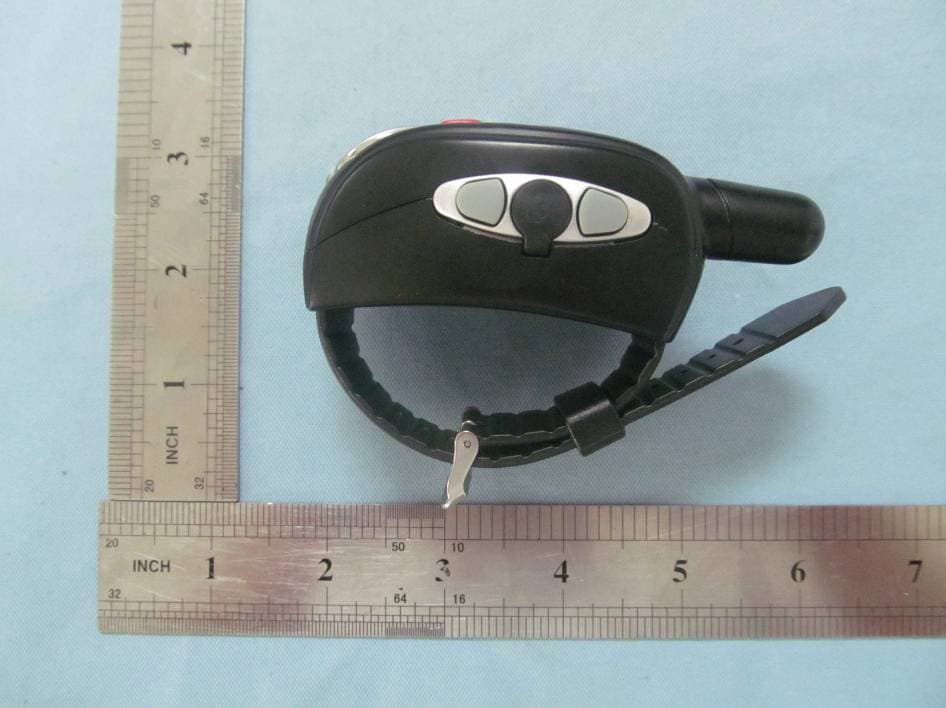
Nov 22, 2012Wrist Watch Walkie Talkie
Equipment Class
FRF - Part 95 Family Radio Face Held Transmitter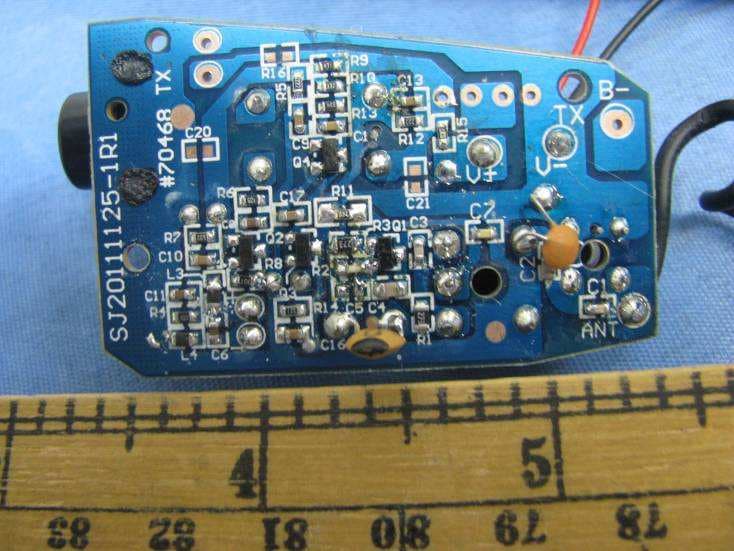
N3EUCLSR70468
May 06, 2012Spy Listener
Equipment Class
DXX - Part 15 Low Power Communication Device Transmitter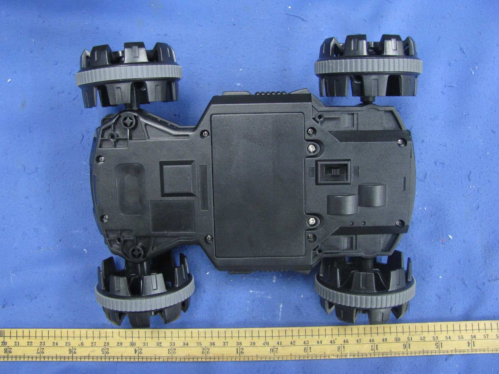
N3ESVC70436TX
Jun 07, 2011Spy Video Car
Equipment Class
DXX - Part 15 Low Power Communication Device Transmitter
N3ESVC70436RX
Jun 07, 2011Spy Video Car
Equipment Class
DXX - Part 15 Low Power Communication Device Transmitter
N3E74047
Apr 26, 2011long range walkie talkie; Model: 74047
Equipment Class
FRF - Part 95 Family Radio Face Held Transmitter