N5GPCCPCC Transponder Reader 134 kHz
Brooks Automation Inc.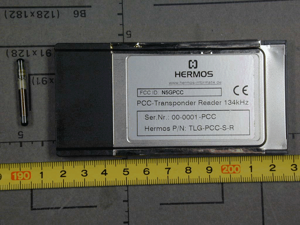
Click to zoom
Application Details
- Equipment Class
- DCD - Part 15 Low Power Transmitter Below 1705 kHz
- Date of Grant
- Jan 29, 2003
- Application Purpose
- Original Equipment
- Date of Application
- Jan 29, 2003
- Equipment Note
- PCC Transponder Reader 134 kHz
- Frequency Range
- 0.13420000 - 0.13420000
- Company
- Brooks Automation Inc.
- Country
- United States
Documents & Files
Document Text
Text extracted from the exhibit documents filed with the FCC. Open a document above to read the original.
Users Manual
2002-09-04 Release: 1.0 ID: ID020064 PC-Card Transponder Reader Technical Report PC-Card Transponder Reader – Release 1.0 HERMOS Informatik GmbH, 95490 Mistelgau, Germany Page 2 of 17 2002-09-04 ID: ID020064 1 System Description...................................................................................3 2 Important Notes........................................................................................4 3 Hardware...................................................................................................5 3.1 Dimensions............................................................................................5 3.2 Technical Data.......................................................................................6 3.3 Power Supply and Current Input.............................................................6 3.4 Additional Instruction for Use..................................................................6 4 Installation to a Notebook or PDA............................................................7 4.1 Notebook or Desktop PC........................................................................7 4.2 PDA.......................................................................................................8 4.2.1 HERMOS PC-Card Reader Test Software for PDA....................8 5 Licenses and Certificates / Declaration of Conformity.............................10 6 Warranty and Liability...............................................................................13 7 Protocol.....................................................................................................14 7.1 Message Structure...............................................................................14 7.2 Commands..........................................................................................15 7.3 Error Messages....................................................................................17 PC-Card Transponder Reader – Release 1.0 HERMOS Informatik GmbH, 95490 Mistelgau, Germany Page 3 of 17 2002-09-04 ID: ID020064 1 System Description The HERMOS PC-Card Transponder Reader is a high frequency identification system using the FM-transmission. The basic item is a transponder working as a forgery-proof electronic identity disc. The reading unit of the system sends an energy impulse via the antenna. The capacitor of the passive, battery-less transponder is charged by this impulse. After that, the transponder returns a signal with the stored data. As a line of sight between transponder and reader is not absolutely necessary, the transponder can also be identified through non-metallic material. The HERMOS PC-Card Transponder Reader is a device to read and write to TIRIS transponder. The card can be used in connection with a notebook or a PDA. PC-Card Transponder Reader – Release 1.0 HERMOS Informatik GmbH, 95490 Mistelgau, Germany Page 4 of 17 2002-09-04 ID: ID020064 2 Important Notes This device complies with Part 15 of the FCC Rules. Operation is subject to the following two conditions: 1) this device may not cause harmful interference , and 2) this device must accept any interference received, including interference that may cause undesired operation. CAUTION: Changes or modifications not expressly approved by the party responsible for compliance could void the user’s authority to operate the equipment. NOTE: This equipment has been tested and found to comply with the limits for a Class B digital device, pursuant to part 15 of the FCC Rules. These limits are designed to provide reasonable protection against harmful interference in a residential installation. This equipment generates, uses and can radiate radio frequency energy and, if not installed and used in accordance with the instructions, may cause harmful interference to radio communications. However, there is no guarantee that interference will not occur in a particular installation. If this equipment does cause harmful interference to radio or television reception, which can be determined by turning the equipment off and on, the user is encouraged to try to correct the interference by one or more of the following measures: —Reorient or relocate the receiving antenna. —Increase the separation between the equipment and receiver. —Connect the equipment into an outlet on a circuit different from that to which the receiver is connected. —Consult the dealer or an experienced radio/TV technician for help. PC-Card Transponder Reader – Release 1.0 HERMOS Informatik GmbH, 95490 Mistelgau, Germany Page 5 of 17 2002-09-04 ID: ID020064 3 Hardware 3.1 Dimensions 6.5 mm 110.1 mm 54 mm Antenna PC-Card Transponder Reader – Release 1.0 HERMOS Informatik GmbH, 95490 Mistelgau, Germany Page 6 of 17 2002-09-04 ID: ID020064 3.2 Technical Data Parameter Value Operation temperature 0°C to +50°C Stock temperature -20°C to +70°C Permissible humidity @ 50°C 25 - 80% Transmitter frequency 134.2 kHz System Requirements: Slot Type: PC-Card Type II Operating System: Win9x/2000/NT/XP/CE Reading and Writing Range (32mm glass transponder): Reading range: ~ 60 mm Writing range: ~ 35 mm 3.3 Power Supply and Current Input Description Value Voltage 5 V DC (+/- 5%) Current (reading and writing) 100 mA Current (passive) 50 mA 3.4 Additional Instruction for Use Never expose the device to a intense change in temperature. Otherwise, water of condensation can develop inside what can lead to damages. Never bend the device or expose it to other mechanical loads. PC-Card Transponder Reader – Release 1.0 HERMOS Informatik GmbH, 95490 Mistelgau, Germany Page 7 of 17 2002-09-04 ID: ID020064 4 Installation to a Notebook or PDA The PC-Card Transponder Reader is suitable for all Windows operating systems. The interface of the reader is comparable with the interface of a serial interface PC- card. 4.1 Notebook or Desktop PC On operating systems which support plug & play, the card will be detected automatically. Then only the delivered *.inf file must be installed. I…
Text truncated - open the document above for the full version.
Attestation Statements
Request for Confidentiality December 03, 2002 PHOENIX TEST-LAB GmbH Königswinkel 10 D32825 Blomberg Germany RE: Certification Application FCC ID: N5GPCC Please be advised that the following information is to be held confidential on behalf of HERMOS Gesellschaft fuer technische Informatik mbH: • Schematics • Block Diagram • Technical Description The application contains technical information which HERMOS Gesellschaft fuer technische Informatik mbH deems to be trade secrets and proprietary. If made public, the information might be used to the disadvantage of the applicant in the market place. Thank you for your attention to this matter. Signatory
External Photos
FCC ID: N5GPCC External Photos Page 1 of 2 FCC ID: N5GPCC External Photos Page 2 of 2
Internal Photos
FCC ID: N5GPCC Internal Photos Page 1 of 2 FCC ID: N5GPCC Internal Photos Page 2 of 2
Test Report
EMV-Prüfzentrum EMI/EMC-Testcenter Page 1 of 26 Pages Straubing, 30 January 2003 T E S T - R E P O R T No. 50831-20515 for TLG-PCC-S-R PCC Transponder Reader 134 kHz Applicant: Hermos Informatik GmbH Purpose of testing: To show compliance with FCC Code of Federal Regulations, Part 15 Subpart C Industry Canada Radio Standards Specification RSS-210 Issue 5, Section 6.1 (Category I Equipment) Note: The test data of this report relate only to the individual item which has been tested. This report shall not be reproduced except in full extent without the written approval of the testing laboratory. EMV-Prüfzentrum EMI/EMC-Testcenter Test report for FCC Part 15 Test Report No. 50831-20515 Page 2 of 26 Pages Table of Contents 1. Administrative Data.....................................................................................3 2. Identification of Test Laboratory .................................................................4 3. Summary of Test Results ...........................................................................5 4. Operation Mode of EUT..............................................................................6 5. Configuration of EUT and Peripheral Devices ............................................7 6. Measuring Methods ....................................................................................8 6.1. Conducted Emission 0.15 MHz - 30 MHz (§15.107) / RSS-210 Section 7.4)...........................................................................8 6.2. Radiated Emission 30 MHz - 1 GHz (FCC §15.109 / RSS-210 Section 7.3).........................................................................10 7. Equipment List ..........................................................................................12 8. Photographs Taken During Testing ..........................................................14 9. List of Measurements ...............................................................................18 9.1. List of Measurements According To FCC Part 15 Subpart B ...........................................................................................19 9.2. List of Measurements According To Industry Canada RSS-210.............................................................................................20 10. Referenced Regulations ...........................................................................21 11. Test Results..............................................................................................22 12. Charts taken during testing.......................................................................26 EMV-Prüfzentrum EMI/EMC-Testcenter Test report for FCC Part 15 Test Report No. 50831-20515 Page 3 of 26 Pages 1. Administrative Data Equipment Under Test (EUT): TLG-PCC-S-R Serial number(s): 00-001-PCC Type of equipment: PCC Transponder Reader 134 kHz Parts/accessories: FCC-ID: N5GPCC Applicant: Hermos Informatik GmbH (full address) Gartenstrasse 19 D-95490 Mistelgau Germany Contract identification: --- Contact person: Mr. Lothar Düngfelder Manufacturer: Hermos Informatik GmbH Receipt of EUT: 19 August 2002 Date of test: October 2002 Note: --- Responsible for testing: Johann Roidt Responsible for test report: Johann Roidt EMV-Prüfzentrum EMI/EMC-Testcenter Test report for FCC Part 15 Test Report No. 50831-20515 Page 4 of 26 Pages 2. Identification of Test Laboratory Test Laboratory: Senton GmbH EMI/EMC Test Center (full address): Aeussere Fruehlingstrasse 45 D-94315 Straubing Germany Contact person: Mr. Johann Roidt Communication: Telephone (+49) 0 94 21 / 55 22-0 Fax (+49) 0 94 21 / 55 22-99 eMail: [email protected] FCC registration number: 90926 Industry Canada file number: IC 3050 EMV-Prüfzentrum EMI/EMC-Testcenter Test report for FCC Part 15 Test Report No. 50831-20515 Page 5 of 26 Pages 3. Summary of Test Results The tested sample complies with the requirements set forth in the FCC Part 15 Subpart C of the Federal Communication Commission (FCC). and the Radio Standards Specification RSS-210 Issue 4, Section 6.1 for Low Power Licence-Exempt Radiocommunication Devices (all frequency bands). Johann Roidt Technical Manager EMV-Prüfzentrum EMI/EMC-Testcenter Test report for FCC Part 15 Test Report No. 50831-20515 Page 6 of 26 Pages 4. Operation Mode of EUT Continuous reading a transponder EMV-Prüfzentrum EMI/EMC-Testcenter Test report for FCC Part 15 Test Report No. 50831-20515 Page 7 of 26 Pages 5. Configuration of EUT and Peripheral Devices Configuration of cables of EUT Not applicable Configuration of peripheral devices connected to EUT All tests were performed with the EUT installed in a Fujitsu LiteLine, model 5053 notebook PC. EMV-Prüfzentrum EMI/EMC-Testcenter Test report for FCC Part 15 Test Report No. 50831-20515 Page 8 of 26 Pages 6. Measuring Methods 6.1. Conducted Emission 0.15 MHz - 30 MHz (§15.107) / RSS-210 Section 7.4) Conducted emissions were measured in the frequency range 0.15 MHz to 30 MHz. The bandwidth of the EMI-Receiver was set to 9 kHz and the detector-function was set to CISPR quasi-peak. The test setup was made in accordance with ANSI C63.4-1992. Measurements were performed on phase and neutral lines of the power-cords of the tested system. Preliminary scans were taken with the detector-function of the EMI- receiver set to peak to determine the conducted EMI-profile of the EUT. At the final test the cables and equipment were placed and moved within the range of positions likely to find their maximum emissions. See figure 1 for the measurement setup. Test equipment used (see equipment list for details): 04, 22, 23, 60, 63 EMV-Prüfzentrum EMI/EMC-Testcenter Test report for FCC Part 15 Test Report No. 50831-20515 Page 9 of 26 Pages 9 10 11 5 8 2 7 4 1 3 6 Figure 1: Example of measurement setup for conducted emission test 1 EUT 8 LISN for EUT 2 Monitor 9 LISN for peripheral device(s) 3 Keyboard 10 Test receiver 4 Mouse 11 Shielded room 5 Parallel Printer 6 Serial Printer 7 Wooden table EMV-Prüfzentrum EMI/EMC-Testcent…
Text truncated - open the document above for the full version.
Test Setup Photos
EMV-Prüfzentrum EMI/EMC-Testcenter Test report for FCC Part 15 Test Report No. 50831-20515 Page 17 of 28 Pages Photos No. 8.1 - 8.2 Test setup for conducted emission test 150 kHz - 30 MHz EMV-Prüfzentrum EMI/EMC-Testcenter Test report for FCC Part 15 Test Report No. 50831-20515 Page 18 of 28 Pages Photos No. 8.3 - 8.4 Test setup for radiated emission pre-test 30 MHz - 1 GHz (fully anechoic room) EMV-Prüfzentrum EMI/EMC-Testcenter Test report for FCC Part 15 Test Report No. 50831-20515 Page 19 of 28 Pages Photos No. 8.5 - 8.6 Test setup for radiated emission final test 30 MHz - 1 GHz (open area test site)
Contact Information
Applicant
Michael Krolak(Member of the Technical Staff)
Technical Contact
Senton GmbHJohann Roidt
[email protected]+49 9421 55 22 13
Aeussere Fruehlingstrasse 45 · Straubing · Germany
Non-Technical Contact
Senton GmbHJohann Roidt
[email protected]+49 9421 55 22 13
Test Firm
TUV SUD Product Service GmbH PS-EMC-STRRainer Heller
Technical Specifications
| # | Rule Parts | Frequency Range | Power Output |
|---|---|---|---|
| 1 | 15C | 0.1342 MHz - 0.1342 MHz | - |
Other Applications from Brooks Automation Inc.
N5GLF40C
Oct 13, 2014RFID Reader
Equipment Class
DCD - Part 15 Low Power Transmitter Below 1705 kHz
N5GLF60C
Jul 09, 2013RFID Reader
Equipment Class
DCD - Part 15 Low Power Transmitter Below 1705 kHz
N5GUF80
Jul 01, 2012RFID UHF Reader
Equipment Class
DSS - Part 15 Spread Spectrum Transmitter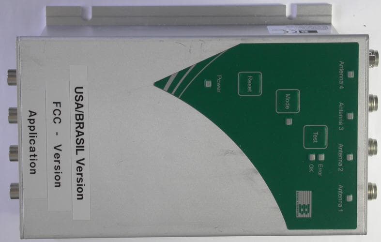
N5GUF70
May 30, 2012RFID UHF Reader
Equipment Class
DSS - Part 15 Spread Spectrum Transmitter
N5GHF5
Mar 09, 2006Inductive Tag Reader
Equipment Class
DXT - Part 15 Low Power Transceiver, Rx Verified