N5GSARInductive Tag System
Brooks Automation Inc.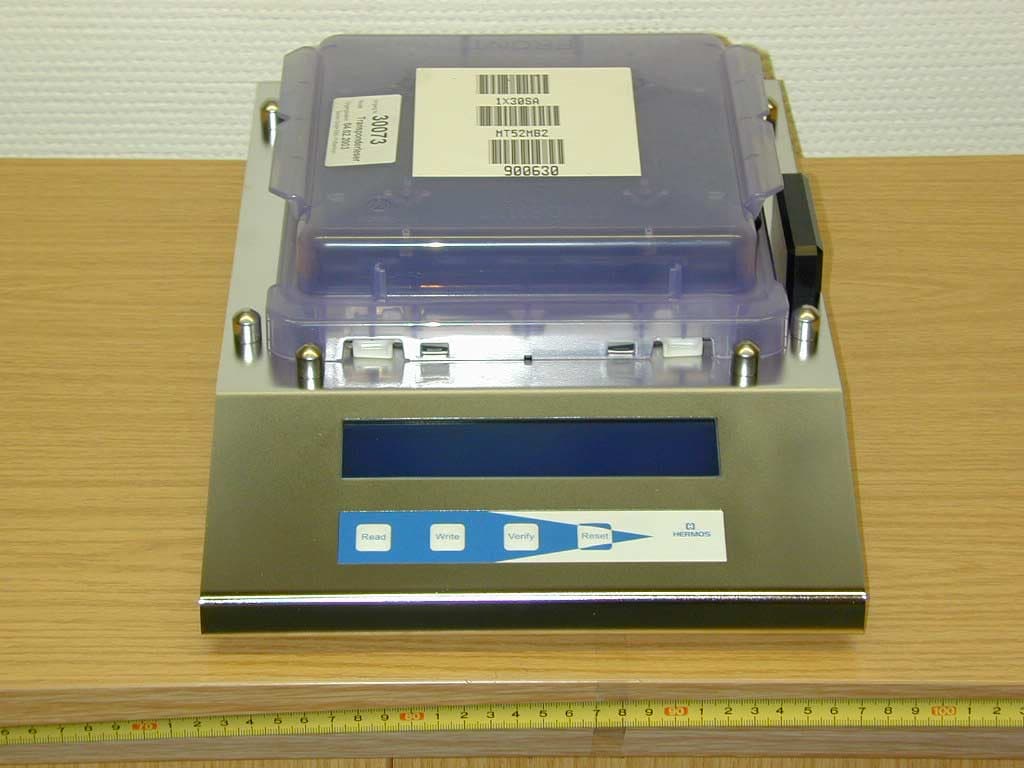
Click to zoom
Application Details
- Equipment Class
- DCD - Part 15 Low Power Transmitter Below 1705 kHz
- Date of Grant
- Jun 09, 2003
- Application Purpose
- Original Equipment
- Date of Application
- Jun 09, 2003
- Equipment Note
- Inductive Tag System
- Frequency Range
- 0.13400000 - 0.13400000
- Company
- Brooks Automation Inc.
- Country
- United States
Documents & Files
Document Text
Text extracted from the exhibit documents filed with the FCC. Open a document above to read the original.
Users Manual
Page 1 of 15 2003-03-21 Release 1.1 ID: ID030017 Software Reticle Read-Write Station Stand Alone Technical Reports Software Reticle Read – Write Station – Stand Alone Technical Reports, Release 1.1 Page 2 of 15 1 HARDWARE DESCRIPTION.................................................................. 3 2 SOFTWARE SPECIFICATION............................................................. 4 3 HARDWARE...........................................................................................6 3.1 BAR CODE READER.............................................................................6 3.2 RETICLE READ / WRITE STATION.........................................................6 4 SOFTWARE............................................................................................7 4.1 FUNCTIONALITY OF BUTTONS..............................................................7 4.2 MENU MODE.......................................................................................8 4.3 DOWNLOAD........................................................................................9 5 FLOWCHARTS....................................................................................10 5.1 NORMAL MODE..................................................................................10 5.2 17 PAGE MODE..................................................................................11 5.3 MENU MODE.....................................................................................12 5.4 BRIGHTNESS MODE............................................................................13 6 ASCII TABLE.......................................................................................14 IMPORTANT NOTE.................................................................................. 3 Software Reticle Read – Write Station – Stand Alone Technical Reports, Release 1.1 Page 3 of 15 1 Hardware Description At the back side of the Reticle Read/Write Station is one RS232 Sub-D male connector labeled with Barcode Reader. The barcode reader P302FZY has to be connected there. The power supply for this unit has to be connected to the female connector at the back. Connect the external power supply (24V) to the connector which is labeled with power supply, and the reader starts working. The RF Tag reader needs about 3 seconds for initialization. The antenna is justified and the display will be initiated. After this the reader shows the current software version and it is in operation mode. Important Note Software Reticle Read – Write Station – Stand Alone Technical Reports, Release 1.1 Page 4 of 15 2 Software Specification The Reticle Read/Write Station is used to write the RSP data, which will be read from the barcode labels on the top of the RSP, to the RF tag of the RSP. Barcode Data: All bar codes are code 69 labels. Label one is the product name, the second is the layer / version and the third is the CID. The information on the labels have to be written to the tag as follows: Page1: lower CID right justified Page2: upper CID right justified Page3: first characters of product names left justified Page4: remaining characters of product names left justified Page5: layer / version left justified Example: BC data: Product Name: 1X30SA Layer / Version: MT52MB2 CID: 900630 RF tag data: Byte 1 2 3 4 5 6 7 8 Page1 0 0 9 0 0 6 3 0 Page2 0 0 0 0 0 0 0 0 Page3 1 X 3 0 S A 0x00 0x00 Page4 0x00 0x00 0x00 0x00 0x00 0x00 0x00 0x00 Page5 M T 5 2 M B 2 0x00 Pages 6 .. 17 are filled with the blank byte filler character (see section 4.2). The product name can be 1-16 characters long. The layer/version can be 1-8 characters long. Any unused bytes on the RF tag are filled with user configurable filler characters (see section 4.2). Software Reticle Read – Write Station – Stand Alone Technical Reports, Release 1.1 Page 5 of 15 Logistical layout of functionality: 1. RSP will be placed on Reticle Read / Write Station. 2. The RF tag will be read automatically and the result will be shown on the display. 3. The operator writes the label data to the tag. Therefore he reads the labels with the bar code reader. If the bar codes were read correctly the operator verifies the data. If everything was OK the operator presses the ‘Write’ button to transmit the data to the RF tag. Not used bytes will be filled with values which are stored as parameters in the software. 4. After a successful writing the pod could be removed from the unit. 5. It is possible to verify the tag data against the bar code labels. Therefore the operator presses the ‘Verify’ button and reads the labels ones more. After that the tag reader gets the information from the RF tag. The software checks the data of both the tag and the bar code and reports any error. 6. If the operator reads a wrong label it is possible to clear the data / memory by pressing the ‘Reset’ button. Software Reticle Read – Write Station – Stand Alone Technical Reports, Release 1.1 Page 6 of 15 3 Hardware 3.1 Bar Code Reader The barcode works with an ASCII protocol which uses the following settings, COM settings: 38.400,N,8,1 (baud rate, parity, data bits, stop bits). The bar code reader is configured as follows: 1.Set all defaults: 2. Fujitsu RS-232C 3. Baud rate 38.400 Note: If the BCR is not configured you have to read these labels in the right order. 3.2 Reticle Read / Write Station The tag reader includes an RF module which is working on the frequency of 134.2 kHz. To display the data, the device has a dot character display module with four lines and 40 signs per line. Additional the unit includes a membrane keyboard with four buttons. The equipment is designed to handle any SEMI-E111 compliant carrier. Software Reticle Read – Write Station – Stand Alone Technical Reports, Release 1.1 Page 7 of 15 4 Software After the equipment was connected to the power supply, the tag reader tune the antenna automatically. If no RSP is placed on the station, the software version is displayed on the display. 4.1 Functionality of But…
Text truncated - open the document above for the full version.
Cover Letter(s)
Request for Confidentiality 10 June 2003 PHOENIX TEST-LAB GmbH Königswinkel 10 D32825 Blomberg Germany RE: Certification Application FCC ID: N5GSAR Please be advised that the following information is to be held confidential on behalf of HERMOS Gesellschaft für technische Informatik mbH: • Schematics • Block Diagram • Technical Description The application contains technical information which HERMOS Gesellschaft für technische Informatik mbH deems to be trade secrets and proprietary. If made public, the information might be used to the disadvantage of the applicant in the market place. Thank you for your attention to this matter. Signatory
External Photos
EMV-Pr ̧fzentrum EMI/EMC-Testcenter FCC-ID: N5GSAR Front of unit EMV-Pr ̧fzentrum EMI/EMC-Testcenter FCC-ID: N5GSAR Rear of unit EMV-Pr ̧fzentrum EMI/EMC-Testcenter FCC-ID: N5GSAR Bottom side of unit
Internal Photos
EMV-Pr ̧fzentrum EMI/EMC-Testcenter FCC-ID: N5GSAR Front view of disassembled unit EMV-Pr ̧fzentrum EMI/EMC-Testcenter FCC-ID: N5GSAR Rear view of top cover EMV-Pr ̧fzentrum EMI/EMC-Testcenter FCC-ID: N5GSAR Top view of main board with RF board mounted EMV-Pr ̧fzentrum EMI/EMC-Testcenter FCC-ID: N5GSAR Top view of printed main board without RF board EMV-Pr ̧fzentrum EMI/EMC-Testcenter FCC-ID: N5GSAR Bottom view of printed main board EMV-Pr ̧fzentrum EMI/EMC-Testcenter FCC-ID: N5GSAR Top view of RF board EMV-Pr ̧fzentrum EMI/EMC-Testcenter FCC-ID: N5GSAR Bottom view of RF board EMV-Pr ̧fzentrum EMI/EMC-Testcenter FCC-ID: N5GSAR Top view of printed RF board without shielding cover EMV-Pr ̧fzentrum EMI/EMC-Testcenter FCC-ID: N5GSAR Bottom view of printed RF board without shielding cover
Test Report
EMV-Pr ̧fzentrum EMI/EMC-Testcenter Page 1 of 55 Pages Straubing, June 5, 2003 T E S T - R E P O R T No. 50831-30073-2B for SAR-Read/Write Station Inductive Tag System Applicant: Hermos Informatik GmbH Purpose of testing: To show compliance with FCC Code of Federal Regulations, CFR 47, Part 15, Subpart C, Sections 15.205, 15.207 and 15.209 Industry Canada Radio Standards Specification RSS-210 Issue 5, Sections 6.2.1, 6.3, 6.6 (Category I Equipment) Note: The test data of this report relate only to the individual item which has been tested. This report shall not be reproduced except in full extent without the written approval of the testing laboratory. EMV-Pr ̧fzentrum EMI/EMC-Testcenter Test Report Form FCC Part 15 Test Report No. 50831-30073-2B Page 2 of 55 Pages Table of Contents 1. Administrative Data ............................................................................................. 3 2. Identification of Test Laboratory .......................................................................... 4 3. Summary of Test Results .................................................................................... 5 4. Deviations from the Test Specifications............................................................... 6 5. Operation Mode of EUT....................................................................................... 7 6. Configuration of EUT and Peripheral Devices ..................................................... 8 7. Measuring Methods ............................................................................................. 9 7.1. Conducted Emission 0.15 MHz - 30 MHz (ß15.207 / IC RSS- 210 sec. 6.6, 7.4)........................................................................................ 10 7.2. Radiated emission 9 kHz - 30 MHz (ß15.205, ß15.209 / IC RSS-210 Sections 6.2.1, 6.3, 13) ............................................................... 12 7.3. Radiated emission 30 MHz - 1 GHz (ß15.205, ß15.209 / IC RSS-210 Sections 6.2.1, 6.3) ..................................................................... 13 8. Photographs of Test Setups .............................................................................. 15 9. Equipment List................................................................................................... 25 10. Referenced Regulations .................................................................................... 30 11. List of Measurements ........................................................................................ 31 11.1. List of Measurements According To FCC Part 15 Subpart C...................... 31 11.2. List of Measurements According To Industry Canada RSS-210..................................................................................................... 31 12. Test Results ...................................................................................................... 32 13. Charts taken during testing................................................................................ 36 14. Additional Information supplementary to the Test Report .................................. 55 EMV-Pr ̧fzentrum EMI/EMC-Testcenter Test Report Form FCC Part 15 Test Report No. 50831-30073-2B Page 3 of 55 Pages 1. Administrative Data Equipment Under Test (EUT): SAR-Read/Write Station Serial number(s): Sample no. 2 Type of equipment: Inductive Tag System Type of emission: 10K0A1D Parts/accessories: with AC/DC adapter ASTEC SA45-3109, serial no. 2178044307 R2 0111C2 EUT contains∑RF module TIRIS RI-RFM-003B-00, Texas Instruments, serial no. 017147 FCC-ID: To be determined Applicant: Hermos Informatik GmbH (full address) Gartenstrafle 19 D-95490 Mistelgau Germany Contract identification: --- Contact person: Mr. Lothar D ̧ngfelder Manufacturer: Hermos Informatik GmbH Receipt of EUT: March 4, 2003 Dates of test: March 4 and 5, 2003 Note: --- Responsible for testing: Rainer Heller Responsible for test report: Rainer Heller EMV-Pr ̧fzentrum EMI/EMC-Testcenter Test Report Form FCC Part 15 Test Report No. 50831-30073-2B Page 4 of 55 Pages 2. Identification of Test Laboratory Test Laboratory: Senton GmbH EMI/EMC Test Center (full address): Aeussere Fruehlingstrasse 45 D-94315 Straubing Germany Contact person: Mr. Johann Roidt Communication: Telephone (+49) 0 94 21 / 55 22-0 Fax (+49) 0 94 21 / 55 22-99 eMail: [email protected] FCC registration number: 90926 Industry Canada file number: IC 3050 EMV-Pr ̧fzentrum EMI/EMC-Testcenter Test Report Form FCC Part 15 Test Report No. 50831-30073-2B Page 5 of 55 Pages 3. Summary of Test Results The tested sample complies with the requirements for set forth in the The Code of Federal Regulations 47, Part 15, Subpart C, Sections 15.205, 15.207 and 15.209 of the Federal Communication Commission (FCC) and the Radio Standards Specification RSS-210 Issue 5, Sections 6.2.1, 6.3 and 6.6 for Low Power Licence-Exempt Radiocommunication Devices of Industry Canada (IC). Johann Roidt Rainer Heller Laboratory Manager Test Engineer EMV-Pr ̧fzentrum EMI/EMC-Testcenter Test Report Form FCC Part 15 Test Report No. 50831-30073-2B Page 6 of 55 Pages 4. Deviations from the Test Specifications All tests were performed without deviations from the test specifications. EMV-Pr ̧fzentrum EMI/EMC-Testcenter Test Report Form FCC Part 15 Test Report No. 50831-30073-2B Page 7 of 55 Pages 5. Operation Mode of EUT - with supply voltage 115 V AC - with AC/DC adapter ASTEC SA45-3109 - RS 232 cable connected - with ground connection - reading tag continuously (test mode) EMV-Pr ̧fzentrum EMI/EMC-Testcenter Test Report Form FCC Part 15 Test Report No. 50831-30073-2B Page 8 of 55 Pages 6. Configuration of EUT and Peripheral Devices Configuration of cables of EUT Item Cable length Serial, part or ID no. Shielded serial interface cable 3 m --- Configuration of peripheral devices connected to EUT Not applicable EMV-Pr ̧fzentrum EMI/EMC-Testcenter Test Report Form FCC Part 15 Test Report No. 50831-30073-2B Page 9 of 55 Pages …
Text truncated - open the document above for the full version.
Test Setup Photos
EMV-Pr ̧fzentrum EMI/EMC-Testcenter Test Report Form FCC Part 15 Test Report No. 50831-30073-2 Page 16 of 55 Pages Photo No. 8.1 Test Setup for Conducted Emissions 150 kHz ñ 30 MHz EMV-Pr ̧fzentrum EMI/EMC-Testcenter Test Report Form FCC Part 15 Test Report No. 50831-30073-2 Page 17 of 55 Pages Photos No. 8.2 and 8.3 Test Setup for Conducted Emissions 150 kHz ñ 30 MHz - continued - EMV-Pr ̧fzentrum EMI/EMC-Testcenter Test Report Form FCC Part 15 Test Report No. 50831-30073-2 Page 18 of 55 Pages Photos No. 8.4 and 8.5 Test Setup for Radiated Emissions 9 kHz ñ 30 MHz (prescan) EMV-Pr ̧fzentrum EMI/EMC-Testcenter Test Report Form FCC Part 15 Test Report No. 50831-30073-2 Page 19 of 55 Pages Photos No. 8.6 and 8.7 Test Setup for Radiated Emissions 9 kHz ñ 30 MHz (final scan) EMV-Pr ̧fzentrum EMI/EMC-Testcenter Test Report Form FCC Part 15 Test Report No. 50831-30073-2 Page 20 of 55 Pages Photos No. 8.8 and 8.9 Test Setup for Radiated Emissions 9 kHz ñ 30 MHz (final scan) - continued - EMV-Pr ̧fzentrum EMI/EMC-Testcenter Test Report Form FCC Part 15 Test Report No. 50831-30073-2 Page 21 of 55 Pages Photos No. 8.10 and 8.11 Test Setup for Radiated Emissions 30 ñ 1000 MHz (prescan) EMV-Pr ̧fzentrum EMI/EMC-Testcenter Test Report Form FCC Part 15 Test Report No. 50831-30073-2 Page 22 of 55 Pages Photos No. 8.12 and 8.13 Test Setup for Radiated Emissions 30 ñ 1000 MHz (prescan) - continued - EMV-Pr ̧fzentrum EMI/EMC-Testcenter Test Report Form FCC Part 15 Test Report No. 50831-30073-2 Page 23 of 55 Pages Photo No. 8.14 Test Setup for Radiated Emissions 30 ñ 1000 MHz (final scan) EMV-Pr ̧fzentrum EMI/EMC-Testcenter Test Report Form FCC Part 15 Test Report No. 50831-30073-2 Page 24 of 55 Pages Photos No. 8.15 and 8.16 Test Setup for Radiated Emissions 30 ñ 1000 MHz (final scan) - continued -
Contact Information
Applicant
Michael Krolak(Member of the Technical Staff)
Technical Contact
Senton GmbHJohann Roidt
[email protected]+49 9421 55 22 13
Aeussere Fruehlingstrasse 45 · Straubing · Germany
Non-Technical Contact
Senton GmbHJohann Roidt
[email protected]+49 9421 55 22 13
Test Firm
TUV SUD Product Service GmbH PS-EMC-STRRainer Heller
Technical Specifications
| # | Rule Parts | Frequency Range | Power Output |
|---|---|---|---|
| 1 | 15C | 0.134 MHz - 0.134 MHz | - |
Other Applications from Brooks Automation Inc.
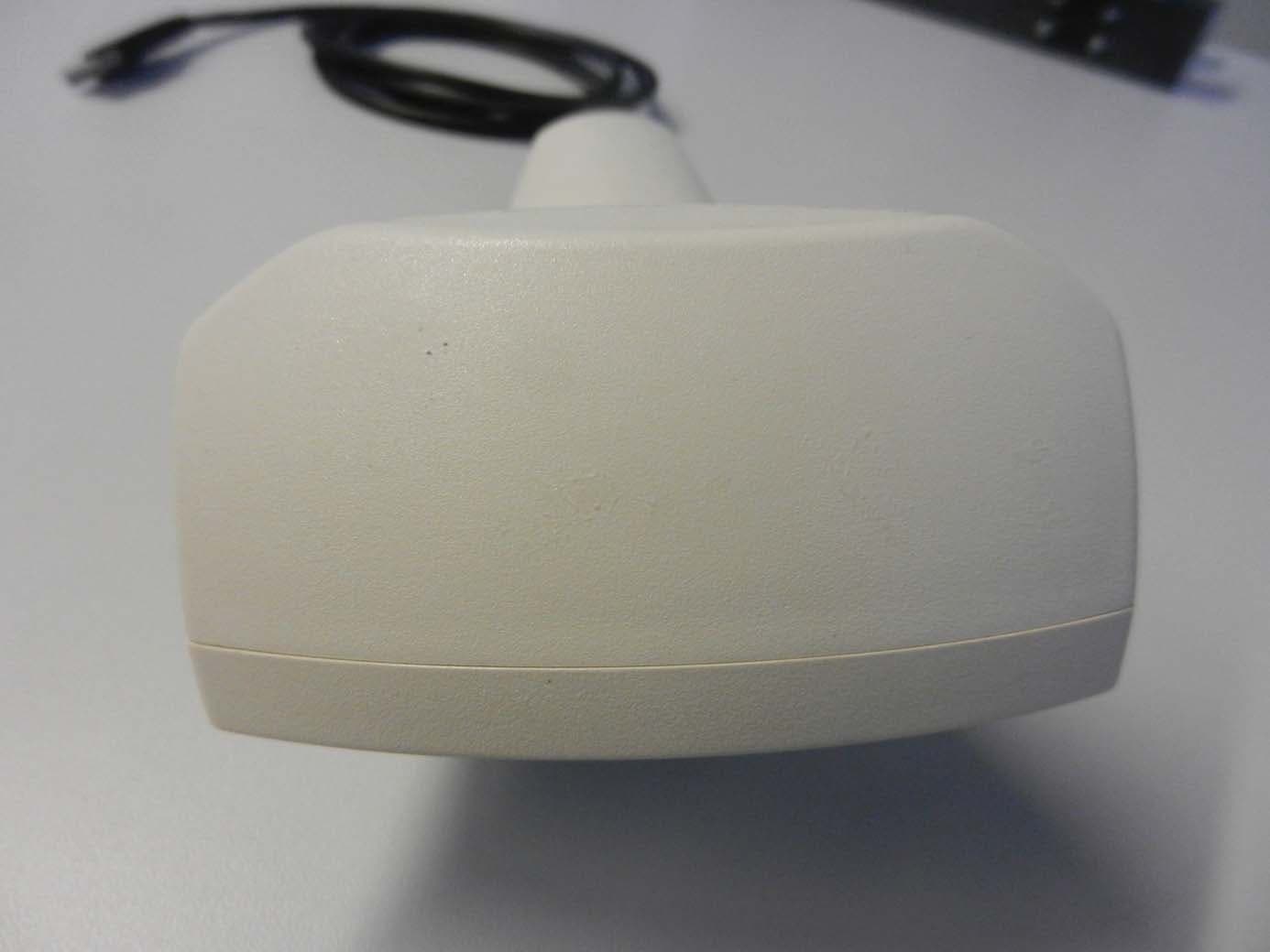
N5GLF40C
Oct 13, 2014RFID Reader
Equipment Class
DCD - Part 15 Low Power Transmitter Below 1705 kHz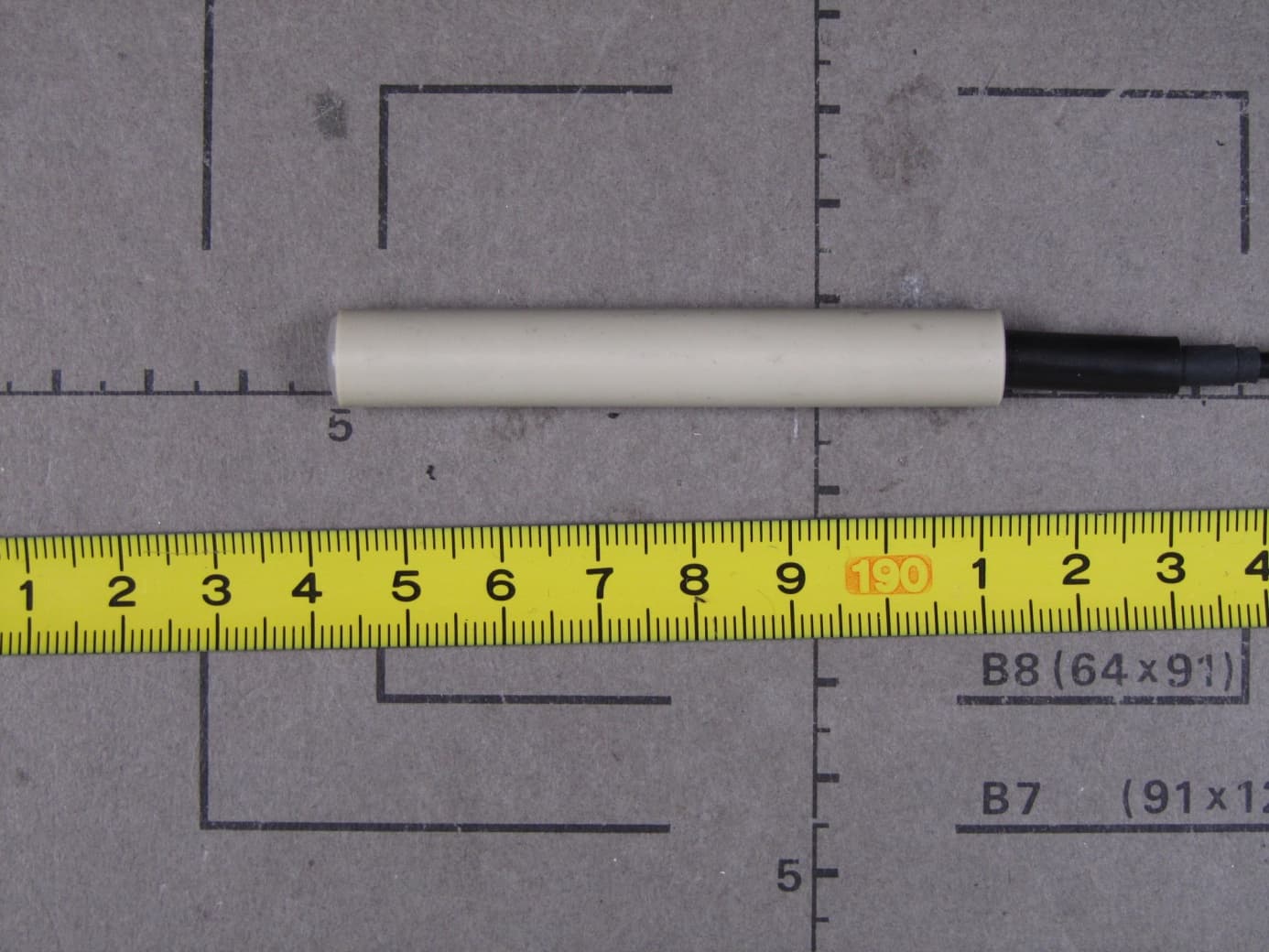
N5GLF60C
Jul 09, 2013RFID Reader
Equipment Class
DCD - Part 15 Low Power Transmitter Below 1705 kHz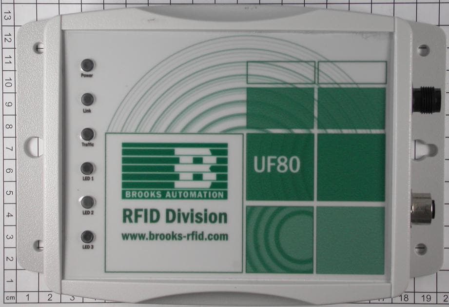
N5GUF80
Jul 01, 2012RFID UHF Reader
Equipment Class
DSS - Part 15 Spread Spectrum Transmitter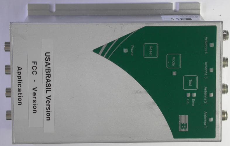
N5GUF70
May 30, 2012RFID UHF Reader
Equipment Class
DSS - Part 15 Spread Spectrum Transmitter
N5GHF5
Mar 09, 2006Inductive Tag Reader
Equipment Class
DXT - Part 15 Low Power Transceiver, Rx Verified