N5GSIDHandheld RFID Reader
Brooks Automation Inc.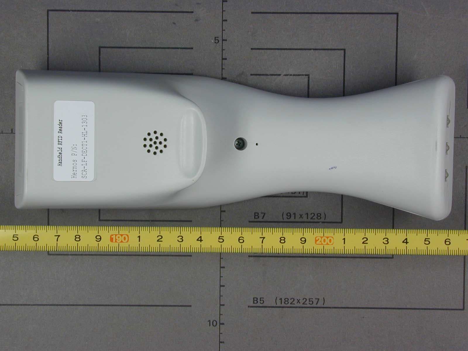
Click to zoom
Application Details
- Equipment Class
- DCD - Part 15 Low Power Transmitter Below 1705 kHz
- Date of Grant
- May 04, 2003
- Application Purpose
- Original Equipment
- Date of Application
- May 04, 2003
- Equipment Note
- Handheld RFID Reader
- Frequency Range
- 0.13430000 - 0.13430000
- Company
- Brooks Automation Inc.
- Country
- United States
Documents & Files
Document Text
Text extracted from the exhibit documents filed with the FCC. Open a document above to read the original.
Users Manual
Page 1 of 21 2002-08-05 Release: 1.0 ID: ID020058 ScanID Technical Reports ScanID Release 1.0 Page 2 of 21 2002-08-05 ID: ID020058 1 INTRODUCTION 3 1.1 SYSTEM DESCRIPTION 3 2 IMPORTANT NOTES 4 3 HARDWARE 5 3.1 MEMBRANE KEYBOARD 6 3.2 TECHNICAL DATA 7 3.3 READING RANGES 8 3.4 CHARGE STATION 8 3.5 LICENSES AND CERTIFICATES / DECLARATION OF CONFORMITY 8 4 SOFTWARE 9 4.1 STANDARD SOFTWARE 9 4.2 ENTER THE MENU 10 4.2.1 Menu Settings 10 4.2.2 Brightness of the Display 10 4.2.3 Read Mode 11 4.2.4 Code Type 12 4.2.5 Page Select 12 4.2.6 HERMOS Menu 14 4.2.7 HERMOS Setup 15 ScanID Release 1.0 Page 3 of 21 2002-08-05 ID: ID020058 1 Introduction 1.1 System Description The ScanID hand held System is a high frequency identification system using the FM-transmission. The basic item is a transponder working as a forgery-proof electronic identity disc. The reading unit of the system sends an energy impulse via the antenna. The capacitor of the passive, battery-less transponder is charged by this impulse. After that, the transponder returns a signal with the stored data. The data received by the transponder reader were checked in the μ-controller and send to the display. The total reading cycle takes less than 100 ms. As a sight-connection between transponder and reader is not absolutely necessary, the transponder can also be identified through non-metallic material. ScanID Release 1.0 Page 4 of 21 2002-08-05 ID: ID020058 2 Important Notes This device complies with Part 15 of the FCC Rules. Operation is subject to the following two conditions: 1) this device may not cause harmful interference , and 2) this device must accept any interference received, including interference that may cause undesired operation. CAUTION: Changes or modifications not expressly approved by the party responsible for compliance could void the user’s authority to operate the equipment. NOTE: This equipment has been tested and found to comply with the limits for a Class B digital device, pursuant to part 15 of the FCC Rules. These limits are designed to provide reasonable protection against harmful interference in a residential installation. This equipment generates, uses and can radiate radio frequency energy and, if not installed and used in accordance with the instructions, may cause harmful interference to radio communications. However, there is no guarantee that interference will not occur in a particular installation. If this equipment does cause harmful interference to radio or television reception, which can be determined by turning the equipment off and on, the user is encouraged to try to correct the interference by one or more of the following measures: —Reorientate or relocate the receiving antenna. —Increase the separation between the equipment and receiver. —Connect the equipment into an outlet on a circuit different from that to which the receiver is connected. —Consult the dealer or an experienced radio/TV technician for help. Please note when opening the device: Static sensitive devices! Handle only at static safe work stations! ScanID Release 1.0 Page 5 of 21 2002-08-05 ID: ID020058 3 Hardware The three load contacts are used to load the ScanID in the load station. The charging activity is shown on the display during the battery charging. The message ‘battery charged’ is shown in case of a full charged battery. Load contacts Membrane ke yboard Graphic display ScanID Release 1.0 Page 6 of 21 2002-08-05 ID: ID020058 3.1 Membrane Keyboard On/Off: This key switches on and off the reader. Push the key for more than 3 seconds to switch off. Read: The ‘Read’ button is used to start the reading of the RF-tag data. In case of an unsuccessful reading, the handheld tries to read the RF tag up to 5 times (default setting). In menu mode this key applies the entered code to enter the HERMOS menu. Select: Normally this key is used to rotate between the different views of the tag information. Also it selects the marked menu items in the menu mode. In triggered mode the select button establishes a channel to the base station to transmit the data. ESC: The ESC key steps out of the current menu up to the start screen. Shift up and down: These buttons are used to scroll in the different menus. Display: Graphic display with a resolution of 128x64 dots. The display can show 8 lines with 21 signs per line. The big font needs two lines per sign. The display memory can hold 32 lines with 21 signs which can be scrolled. ScanID Release 1.0 Page 7 of 21 2002-08-05 ID: ID020058 3.2 Technical Data Parameter Value Operation temperature 0 to +50°C Stock temperature -25 to +70 °C Permissible humidity @ 50C° 25 - 80 % Transmitter frequency LF 134.2 kHz Typical period of charging impulse 50ms Max. repeat of reading 8/s Protection mode IP 40 Housing material ABS Weight about 300g Li-Ion Accu 7,2 V / 1450 mAh The accumulator is designed to read more than 2500 tags before you have to reload the ScanID. The ScanID turn off automatically after a adjustable time – typically 60 seconds. a1 ScanID Release 1.0 Page 8 of 21 2002-08-05 ID: ID020058 3.3 Reading Ranges The reading range is only valid for the transponder types Read only, Read/Write and for the first page of the multipage transponder. If you want to read another page than page 1 of a multipage transponder, the transponder requires the page number. In this case the reading range can be reduced. Rod Antenna: 2,4 inch (Transponder parallel to antenna) Frame Antenna: 4 inch (Transponder parallel to axis of frame) 3.4 Charge Station The charge station charges automatically the li-ion accumulator. The charging time is about 4 hours, a message occurred on the display, when the device is charged. The supply voltage is 100-240V AC. The housing of this charge station is made of ABS or high-grade steel. The charge station can be mounted horizontal or vertical. 3.5 Licenses and Certificates / Declaration of Conformity • • FCC ID: N5GSID Compliance with: FCC Code of Federal Regulations, Part 15 Subpart C, Se…
Text truncated - open the document above for the full version.
Cover Letter(s)
Request for Confidentiality 02 May 2003 PHOENIX TEST-LAB GmbH Königswinkel 10 D32825 Blomberg Germany RE: Certification Application FCC ID: N5GSID Please be advised that the following information is to be held confidential on behalf of HERMOS Gesellschaft für technische Informatik mbH: • Schematics • Parts Lists • Block Diagram • Technical Description The application contains technical information which HERMOS Gesellschaft für technische Informatik mbH deems to be trade secrets and proprietary. If made public, the information might be used to the disadvantage of the applicant in the market place. Thank you for your attention to this matter. Signatory
External Photos
EMV-Pr ̧fzentrum EMI/EMC-Testcenter FCC-ID: N5GSID Front of unit EMV-Pr ̧fzentrum EMI/EMC-Testcenter FCC-ID: N5GSID Rear of unit
ID Label/Location Info
This device complies with Part 15 of the FCC Rules, Operation is subject to the foll owing two conditions: (1) this device may not cause harmful interference and (2) this device must accept any interference received, including interference that may cause undesired operation. Handheld RFID Reader Hermos P/N: SCA - LF - WRT - HL1202 Ser. - Nr. 00 - 000B - SCA www.hermos.informatik.de FCC - ID: N5GSID
Internal Photos
EMV-Pr ̧fzentrum EMI/EMC-Testcenter FCC-ID: N5GSID Unit opened EMV-Pr ̧fzentrum EMI/EMC-Testcenter FCC-ID: N5GSID Top view of printed main board of unit EMV-Pr ̧fzentrum EMI/EMC-Testcenter FCC-ID: N5GSID Top view of printed main board of unit with display removed EMV-Pr ̧fzentrum EMI/EMC-Testcenter FCC-ID: N5GSID Bottom view of printed main board of unit EMV-Pr ̧fzentrum EMI/EMC-Testcenter FCC-ID: N5GSID Bottom view of printed main board of unit with RF board removed EMV-Pr ̧fzentrum EMI/EMC-Testcenter FCC-ID: N5GSID Top view of printed RF board without shielding cover
Test Report
EMV-Pr ̧fzentrum EMI/EMC-Testcenter Page 1 of 67 Pages Straubing, April 18, 2003 T E S T - R E P O R T No. 50831-30106-1 for ScanID Handheld RFID Reader Applicant: Hermos Informatik GmbH Purpose of testing: To show compliance with FCC Code of Federal Regulations, CFR 47, Part 15, Subpart C, Sections 15.205, 15.209 Industry Canada Radio Standards Specification RSS-210 Issue 5, Sections 6.2.1, 6.3, 6.6 (Category I Equipment) Note: The test data of this report relate only to the individual item which has been tested. This report shall not be reproduced except in full extent without the written approval of the testing laboratory. EMV-Pr ̧fzentrum EMI/EMC-Testcenter FCC-ID: N5GSID Test Report No. 50831-30106-1 Page 2 of 67 Pages Table of Contents 1. Administrative Data ............................................................................................. 3 2. Identification of Test Laboratory .......................................................................... 4 3. Summary of Test Results .................................................................................... 5 4. Deviations from the Test Specifications............................................................... 6 5. Operation Mode of EUT....................................................................................... 7 6. Configuration of EUT and Peripheral Devices ..................................................... 8 7. Measuring Methods ............................................................................................. 9 7.1. Radiated emission 9 kHz - 30 MHz (ß15.205, ß15.209 / IC RSS-210 Sections 6.2.1, 6.3) ..................................................................... 10 7.2. Radiated emission 30 MHz - 1 GHz (ß15.205, ß15.209 / IC RSS-210 Sections 6.2.1, 6.3) ..................................................................... 11 8. Photographs of Test Setups .............................................................................. 13 8.1. Photographs of Test Setups for three orthogonal axes............................... 14 8.2. Photographs of Test Setups for different mesurements.............................. 21 9. Equipment List................................................................................................... 26 10. Referenced Regulations .................................................................................... 31 11. List of Measurements ........................................................................................ 32 11.1. List of Measurements According To FCC Part 15 Subpart C...................... 32 11.2. List of Measurements According To Industry Canada RSS-210..................................................................................................... 32 12. Test Results ...................................................................................................... 33 13. Charts taken during testing................................................................................ 36 14. Additional Information supplementary to the Test Report .................................. 67 EMV-Pr ̧fzentrum EMI/EMC-Testcenter FCC-ID: N5GSID Test Report No. 50831-30106-1 Page 3 of 67 Pages 1. Administrative Data Equipment Under Test (EUT): ScanID Serial number(s): Sample no. 1 Type of equipment: Handheld RFID Reader Type of emission: 10K0A1D Parts/accessories: --- FCC-ID: N5GSID Applicant: Hermos Informatik GmbH (full address) Gartenstrafle 19 D-95490 Mistelgau Germany Contract identification: --- Contact person: Mr. Lothar D ̧ngfelder Manufacturer: Hermos Informatik GmbH Receipt of EUT: March 3, 2003 Dates of test: March 3 to 5, 2003 Note: --- Responsible for testing: Rainer Heller Responsible for test report: Rainer Heller EMV-Pr ̧fzentrum EMI/EMC-Testcenter FCC-ID: N5GSID Test Report No. 50831-30106-1 Page 4 of 67 Pages 2. Identification of Test Laboratory Test Laboratory: Senton GmbH EMI/EMC Test Center (full address): Aeussere Fruehlingstrasse 45 D-94315 Straubing Germany Contact person: Mr. Johann Roidt Communication: Telephone (+49) 0 94 21 / 55 22-0 Fax (+49) 0 94 21 / 55 22-99 eMail: [email protected] FCC registration number: 90926 Industry Canada file number: IC 3050 EMV-Pr ̧fzentrum EMI/EMC-Testcenter FCC-ID: N5GSID Test Report No. 50831-30106-1 Page 5 of 67 Pages 3. Summary of Test Results The tested sample complies with the requirements for set forth in the The Code of Federal Regulations 47, Part 15, Subpart C, Sections 15.205, 15.207 and 15.209 of the Federal Communication Commission (FCC) and the Radio Standards Specification RSS-210 Issue 5, Sections 6.2.1, 6.3 and 6.6 for Low Power Licence-Exempt Radiocommunication Devices of Industry Canada (IC). Johann Roidt Rainer Heller Laboratory Manager Test Engineer EMV-Pr ̧fzentrum EMI/EMC-Testcenter FCC-ID: N5GSID Test Report No. 50831-30106-1 Page 6 of 67 Pages 4. Deviations from the Test Specifications All tests were performed without deviations from the test specifications. EMV-Pr ̧fzentrum EMI/EMC-Testcenter FCC-ID: N5GSID Test Report No. 50831-30106-1 Page 7 of 67 Pages 5. Operation Mode of EUT - FCC test setup as stand alone device - with fully charged accumulator - without tag or - reading tag continuously (distance 1 cm) EMV-Pr ̧fzentrum EMI/EMC-Testcenter FCC-ID: N5GSID Test Report No. 50831-30106-1 Page 8 of 67 Pages 6. Configuration of EUT and Peripheral Devices Configuration of cables of EUT Not applicable Configuration of peripheral devices connected to EUT Not applicable EMV-Pr ̧fzentrum EMI/EMC-Testcenter FCC-ID: N5GSID Test Report No. 50831-30106-1 Page 9 of 67 Pages 7. Measuring Methods EMV-Pr ̧fzentrum EMI/EMC-Testcenter FCC-ID: N5GSID Test Report No. 50831-30106-1 Page 10 of 67 Pages 7.1. Radiated emission 9 kHz - 30 MHz (ß15.205, ß15.209 / IC RSS-210 Sections 6.2.1, 6.3) Radiated emissions in the frequency range 9 kHz ñ 30 MHz were measured initially at a distance of 3 meters. A prescan at 3 meter distance were performed in a shielded room with the det…
Text truncated - open the document above for the full version.
Test Setup Photos
EMV-Pr ̧fzentrum EMI/EMC-Testcenter FCC-ID: N5GSID Test Report No. 50831-30106-1 Page 15 of 67 Pages Photos No. 8.1 and 8.2 Test Setup with EUT in horizontal position with rear side on table EMV-Pr ̧fzentrum EMI/EMC-Testcenter FCC-ID: N5GSID Test Report No. 50831-30106-1 Page 16 of 67 Pages Photos No. 8.3 and 8.4 Test Setup with EUT in horizontal position with rear side on table - continued - EMV-Pr ̧fzentrum EMI/EMC-Testcenter FCC-ID: N5GSID Test Report No. 50831-30106-1 Page 17 of 67 Pages Photos No. 8.5 and 8.6 Test Setup with EUT in horizontal position with right side on table EMV-Pr ̧fzentrum EMI/EMC-Testcenter FCC-ID: N5GSID Test Report No. 50831-30106-1 Page 18 of 67 Pages Photos No. 8.7 and 8.8 Test Setup with EUT in horizontal position with right side on table - continued - EMV-Pr ̧fzentrum EMI/EMC-Testcenter FCC-ID: N5GSID Test Report No. 50831-30106-1 Page 19 of 67 Pages Photos No. 8.9 and 8.10 Test Setup with EUT in vertical position with bottom side on table EMV-Pr ̧fzentrum EMI/EMC-Testcenter FCC-ID: N5GSID Test Report No. 50831-30106-1 Page 20 of 67 Pages Photos No. 8.11 and 8.12 Test Setup with EUT in vertical position with bottom side on table - continued - EMV-Pr ̧fzentrum EMI/EMC-Testcenter FCC-ID: N5GSID Test Report No. 50831-30106-1 Page 21 of 67 Pages 8.2. Photographs of Test Setups for different mesurements EMV-Pr ̧fzentrum EMI/EMC-Testcenter FCC-ID: N5GSID Test Report No. 50831-30106-1 Page 22 of 67 Pages Photo No. 8.13 Test Setup for Radiated Emissions 9 kHz ñ 30 MHz (prescan) EMV-Pr ̧fzentrum EMI/EMC-Testcenter FCC-ID: N5GSID Test Report No. 50831-30106-1 Page 23 of 67 Pages Photo No. 8.14 Test Setup for Radiated Emissions 9 kHz ñ 30 MHz (final scan) EMV-Pr ̧fzentrum EMI/EMC-Testcenter FCC-ID: N5GSID Test Report No. 50831-30106-1 Page 24 of 67 Pages Photo No. 8.15 Test Setup for Radiated Emissions 30 ñ 1000 MHz (prescan) EMV-Pr ̧fzentrum EMI/EMC-Testcenter FCC-ID: N5GSID Test Report No. 50831-30106-1 Page 25 of 67 Pages Photo No. 8.16 Test Setup for Radiated Emissions 30 ñ 1000 MHz (final scan)
Contact Information
Applicant
Michael Krolak(Member of the Technical Staff)
Technical Contact
Senton GmbHJohann Roidt
[email protected]+49 9421 55 22 13
Aeussere Fruehlingstrasse 45 · Straubing · Germany
Non-Technical Contact
Senton GmbHJohann Roidt
[email protected]+49 9421 55 22 13
Test Firm
TUV SUD Product Service GmbH PS-EMC-STRRainer Heller
Technical Specifications
| # | Rule Parts | Frequency Range | Power Output |
|---|---|---|---|
| 1 | 15C | 0.1343 MHz - 0.1343 MHz | - |
Other Applications from Brooks Automation Inc.
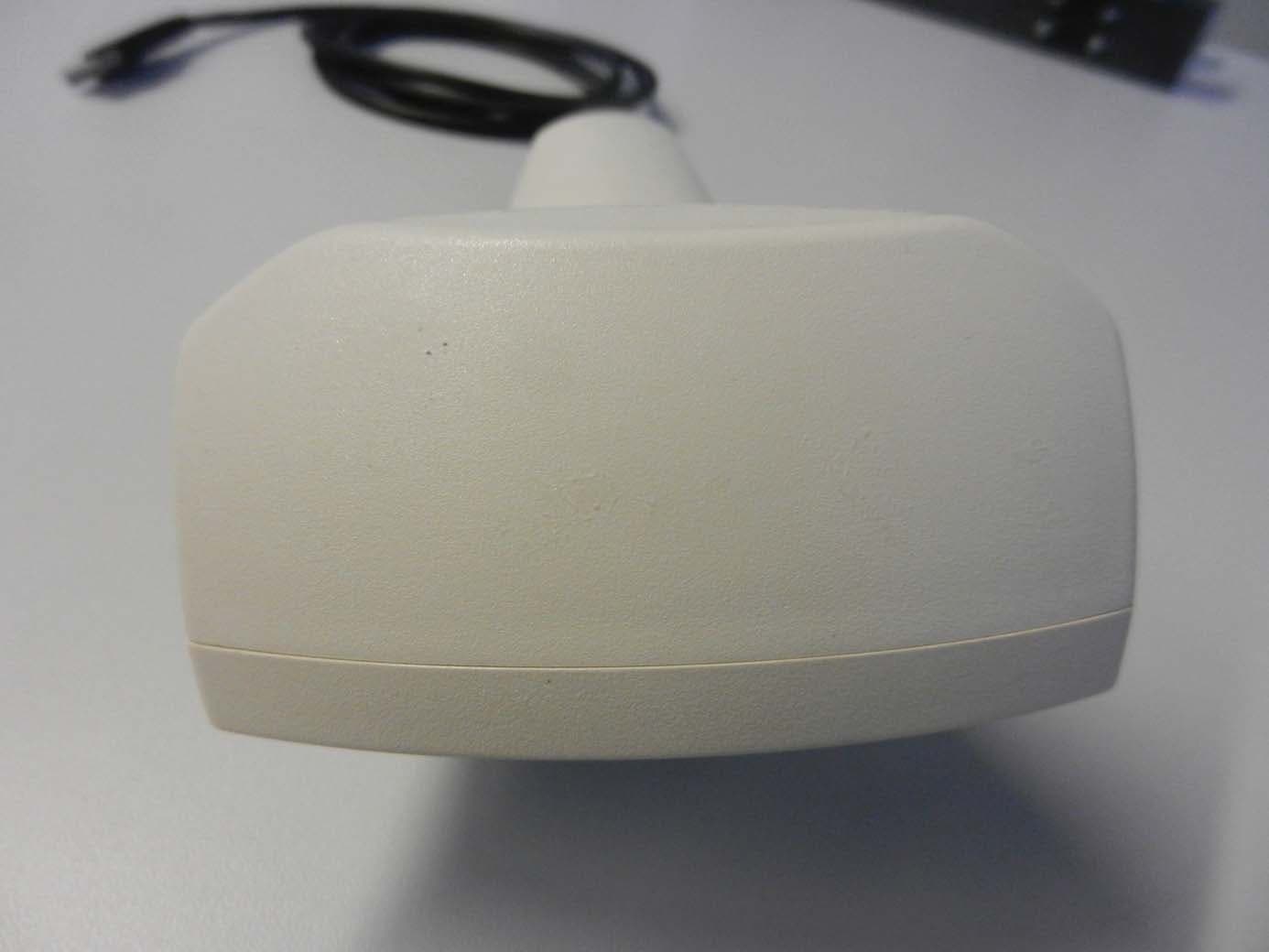
N5GLF40C
Oct 13, 2014RFID Reader
Equipment Class
DCD - Part 15 Low Power Transmitter Below 1705 kHz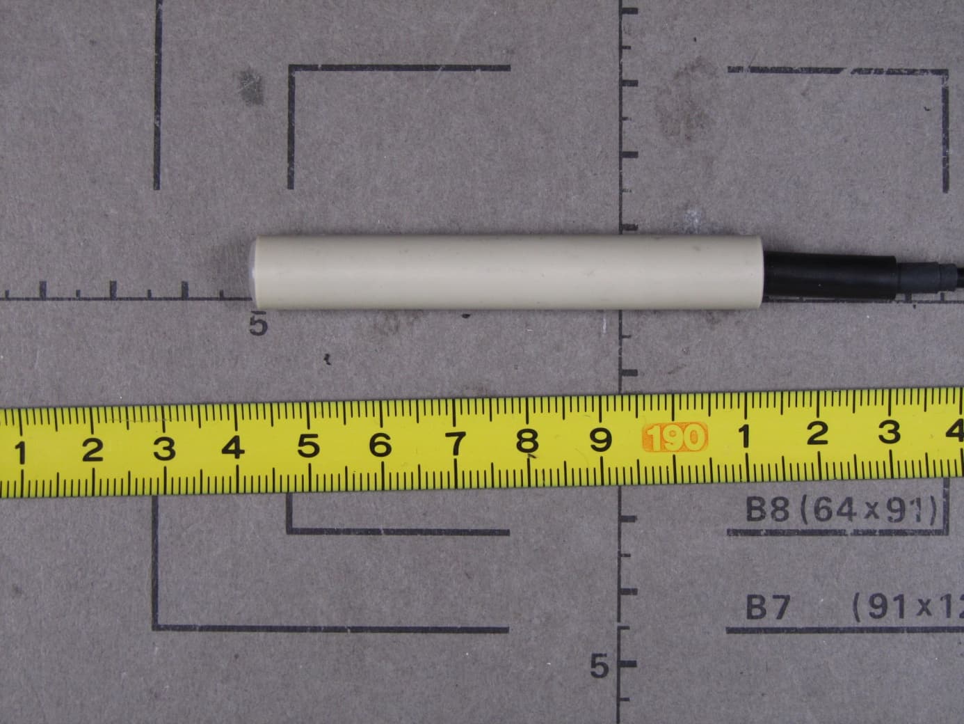
N5GLF60C
Jul 09, 2013RFID Reader
Equipment Class
DCD - Part 15 Low Power Transmitter Below 1705 kHz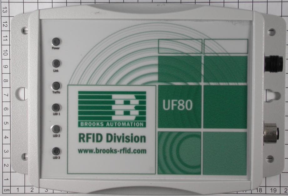
N5GUF80
Jul 01, 2012RFID UHF Reader
Equipment Class
DSS - Part 15 Spread Spectrum Transmitter
N5GUF70
May 30, 2012RFID UHF Reader
Equipment Class
DSS - Part 15 Spread Spectrum Transmitter
N5GHF5
Mar 09, 2006Inductive Tag Reader
Equipment Class
DXT - Part 15 Low Power Transceiver, Rx Verified