N5GTLGTransponder Reader System
Brooks Automation Inc.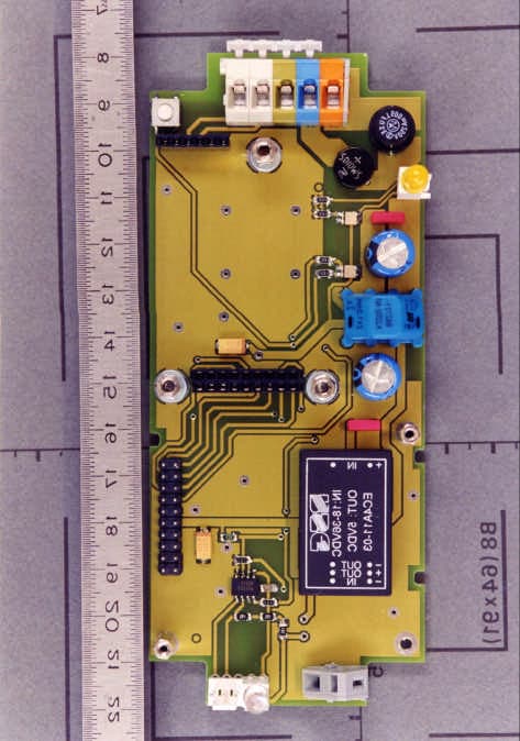
Click to zoom
Application Details
- Equipment Class
- DCD - Part 15 Low Power Transmitter Below 1705 kHz
- Date of Grant
- Jan 12, 2000
- Application Purpose
- Original Equipment
- Date of Application
- Nov 21, 1999
- Equipment Note
- Transponder Reader System
- Frequency Range
- 0.13420000 - 0.13420000
- Company
- Brooks Automation Inc.
- Country
- United States
Documents & Files
Document Text
Text extracted from the exhibit documents filed with the FCC. Open a document above to read the original.
Users Manual
Page 1 of 22 2000-01-11 Release 2.2 LON Transponder Reader Technical Reports Hermos Technical Reports Release 2.1Page 2 of 22 1SYSTEM DESCRIPTION3 2IMPORTANT NOTES:4 3HARDWARE5 3.1CONSTRUCTION5 3.2STANDARD HOUSING7 3.3TERMINAL CONNECTION8 4TECHNICAL DATA10 4.1POWER SUPPLY AND CURRENT INPUT11 4.2ADDITIONAL INSTRUCTION FOR USE11 5INSTALLATION DESCRIPTION OF THE LON-NETWORK12 5.1TRANSMISSION MEDIUM12 5.2NETWORK TOPOLOGY12 6LICENSES AND CERTIFCATES14 7WARRANTY AND LIABILITY15 8READING AND WRITING RANGES16 8.1READING RANGE STICK ANTENNA16 8.2WRITING RANGE STICK ANTENNA17 8.3READING RANGE MICRO ANTENNA18 8.4WRITING RANGE MICRO ANTENNA19 8.5READING RANGE FRAME ANTENNA20 8.6WRITING RANGE FRAME ANTENNA21 9ACCESSORIES22 9.1CABLING OF POWER AND LON22 9.2CONNECTION OF THE EXTERNAL SENSOR/ACTOR22 9.3POWER SUPPLY22 Hermos Technical Reports Release 2.1Page 3 of 22 1 System Description The HERMOS transponder reader system is used in the semiconductor industry for the identification of the wafer-carrier. It is a high frequency identification system using the FM-transmission. The basic item is a transponder working as a forgery-proof electronic identity disc. The reader of the system sends an energy impulse via the antenna. The capacitor of the passive, battery-less transponder is charged by this impulse. After that, the transponder returns a signal with the stored data. The total reading cycle takes less than 100 ms. As a sight-connection between transponder and reader is not absolutely necessary, the transponder can also be identified through non-metallic material. The HERMOS transponder reading unit is a LON-node. LON is a control network for distributed systems and has been developed by the US company Echelon. The LONWORKS-technology corresponds to the SEMI (Semiconductor Equipment Materials International)-Standard (E54.6). The data received by the transponder reader are transmitted to equipment, terminalserver or host systems by the LON-network. Hermos Technical Reports Release 2.1Page 4 of 22 2 Important Notes: This device complies with Part 15 of the FCC Rules. Operation is subject to the following two conditions: 1) this device may not cause harmful interference , and 2) this device must accept any interference received, including interference that may cause undesired operation. CAUTION: Changes or modifications not expressly approved by the party responsible for compliance could void the user’s authority to operate the equipment. NOTE: This equipment has been tested and found to comply with the limits for a Class B digital device, pursuant to part 15 of the FCC Rules. These limits are designed to provide reasonable protection against harmful interference in a residential installation. This equipment generates, uses and can radiate radio frequency energy and, if not installed and used in accordance with the instructions,may cause harmful interference to radio communications. However, there is no guarantee that interference will not occur in a particular installation. If this equip-ment does cause harmful interference to radio or television reception, which can be determined by turning the equipment off and on, the user is encouraged to try to correct the interference by one or more of the following measures: —Reorient or relocate the receiving antenna. —Increase the separation between the equip-ment and receiver. —Connect the equipment into an outlet on a circuit different from that to which the receiver is connected. —Consult the dealer or an experienced radio/TV technician for help. Hermos Technical Reports Release 2.1Page 5 of 22 3 Hardware 3.1 Construction SERVICE-key Fuse Control-LED red:SERVICE green: READ Control-module Connection terminal Screw connection for antenna Shield connection for antenna lead HF-module External input and output Attention: ALL ANTENNA RESONANT CIRCUIT COMPONENTS CAN CARRY HIGH VOLTAGE! Connection for ext. input and output Conncection for power and LON- bus Output for antenna C C S - + S XS1 XS2 Hermos Technical Reports Release 2.1Page 6 of 22 Control-LED The two-coloured control-LED (red/green) shows the actual operation status of the device. Red: The control-LED glows shortly red, if the SERVICE-button had been pushed. If the LED blinks red or glows red continuously, the device is unconfigured or applicationless. In this case, please contact the manufacturer. Green: The control-LED glows shortly green, if the device tries to read or write. SERVICE-button The SERVICE-button can be used to install the reader into the network. Terminal screw for antenna shielding The shield of the antenna has to be sticked on the terminal screw. Control-module The control-module is the control unit of the device. On the module, there is the controller (Neuron-chip), a plug-in program memory (FlashEEPROM) and the FTT10-A transceiver for the communication on the LON-bus. HF-module The HF-module is the analog part of the device. It triggers the antenna and transmits the received data to the control-module. Hermos Technical Reports Release 2.1Page 7 of 22 3.2 Standard Housing Hermos Technical Reports Release 2.1Page 8 of 22 3.3 Terminal Connection Built-in male plug, plastic (supply and LON) PIN signal 1+24V 20V 3 LON 4 LON 5shield Up to serial-no. TLG-00-1999: Pin 5 (shield) has to be connected! Option: built-in female plug, metal (external sensor/actor) PINsignal 1+24V Output 20V 3IN NPN 4+5V 5OUT LED 1 2 3 4 5 Sensor is not connected. 3 4 5 1 2 positive logic negative logic + 10..30V DC 0 V Type: NPN Output Q + 10..30V DC 0 V Type: NPN Output Q Please advise in your order which sensor logic will be used! Hermos Technical Reports Release 2.1Page 9 of 22 For the actor signal a LED without a shunt (connection to PIN 4 and 5) is required. For the sensor a potential free contact (connection to PIN 2 and 3) or a 24V- sensor (3 wire version with npn-output, connection to PIN 1 to 3) is required. Important: Up to serial-no: TLG-00-1999 For devices which have been delivered before the end of N…
Text truncated - open the document above for the full version.
External Photos
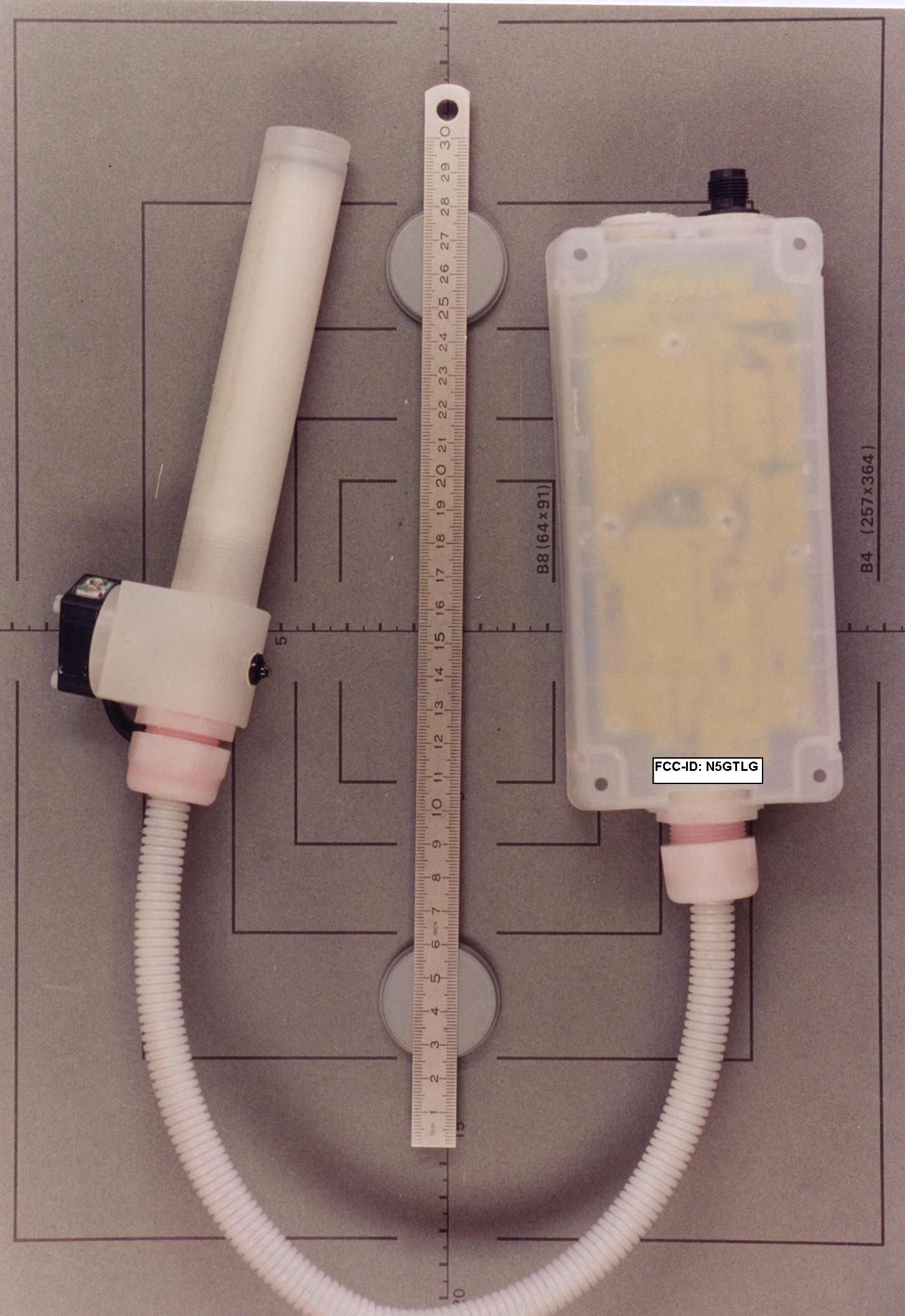
FCC-ID: N5GTLG Photographs of EUT Page 1 of 22 Pages EMV-PrüfzentrumEMI/EMC-Testcenter 1. Photographs of NBase 3.2 with appropriate antennae FCC-ID: N5GTLG Photographs of EUT Page 2 of 22 Pages EMV-PrüfzentrumEMI/EMC-Testcenter 1.1.Photographs of NBase 3.2 with rod antenna FCC-ID: N5GTLG Photographs of EUT Page 3 of 22 Pages EMV-PrüfzentrumEMI/EMC-Testcenter Photo No. 1.1.1 Top view of transponder reader system FCC-ID: N5GTLG Photographs of EUT Page 4 of 22 Pages EMV-PrüfzentrumEMI/EMC-Testcenter Photo No. 1.1.2 Bottom view of transponder reader system FCC-ID: N5GTLG Photographs of EUT Page 5 of 22 Pages EMV-PrüfzentrumEMI/EMC-Testcenter 1.2. Photographs of NBase 3.2 with micro antenna FCC-ID: N5GTLG Photographs of EUT Page 6 of 22 Pages EMV-PrüfzentrumEMI/EMC-Testcenter Photo No. 1.2.1 Top view of transponder reader system FCC-ID: N5GTLG Photographs of EUT Page 7 of 22 Pages EMV-PrüfzentrumEMI/EMC-Testcenter Photo No. 1.2.2 Bottom view of transponder reader system FCC-ID: N5GTLG Photographs of EUT Page 8 of 22 Pages EMV-PrüfzentrumEMI/EMC-Testcenter 1.3 Photographs of NBase 3.2 with loop antenna FCC-ID: N5GTLG Photographs of EUT Page 9 of 22 Pages EMV-PrüfzentrumEMI/EMC-Testcenter Photo No. 1.3.1 Top view of transponder reader system FCC-ID: N5GTLG Photographs of EUT Page 10 of 22 Pages EMV-PrüfzentrumEMI/EMC-Testcenter Photo No. 1.3.2 Bottom view of transponder reader system FCC-ID: N5GTLG Photographs of EUT Page 11 of 22 Pages EMV-PrüfzentrumEMI/EMC-Testcenter 2. Photographs of base unit NBase 3.2 FCC-ID: N5GTLG Photographs of EUT Page 12 of 22 Pages EMV-PrüfzentrumEMI/EMC-Testcenter Photo No. 2.1 Top view of base unit without cover FCC-ID: N5GTLG Photographs of EUT Page 13 of 22 Pages EMV-PrüfzentrumEMI/EMC-Testcenter Photo No. 2.2 Bottom view of base unit without cover FCC-ID: N5GTLG Photographs of EUT Page 14 of 22 Pages EMV-PrüfzentrumEMI/EMC-Testcenter Photo No. 2.3 Top view of base unit without RF and flash control module FCC-ID: N5GTLG Photographs of EUT Page 15 of 22 Pages EMV-PrüfzentrumEMI/EMC-Testcenter Photo No. 2.4 Bottom view of base unit without RF and flash control module FCC-ID: N5GTLG Photographs of EUT Page 16 of 22 Pages EMV-PrüfzentrumEMI/EMC-Testcenter Photo No. 2.5 Top view of printed board of RF module FCC-ID: N5GTLG Photographs of EUT Page 17 of 22 Pages EMV-PrüfzentrumEMI/EMC-Testcenter Photo No. 2.6 Bottom view of printed board of RF module FCC-ID: N5GTLG Photographs of EUT Page 18 of 22 Pages EMV-PrüfzentrumEMI/EMC-Testcenter Photo No. 2.7 Top view of disassembled RF module FCC-ID: N5GTLG Photographs of EUT Page 19 of 22 Pages EMV-PrüfzentrumEMI/EMC-Testcenter Photo No. 2.8 Top view of printed board of RF module without cover FCC-ID: N5GTLG Photographs of EUT Page 20 of 22 Pages EMV-PrüfzentrumEMI/EMC-Testcenter Photo No. 2.9 Bottom view of printed board of RF module without cover FCC-ID: N5GTLG Photographs of EUT Page 21 of 22 Pages EMV-PrüfzentrumEMI/EMC-Testcenter Photo No. 2.10 Top view of printed board of flash control module FCC-ID: N5GTLG Photographs of EUT Page 22 of 22 Pages EMV-PrüfzentrumEMI/EMC-Testcenter Photo No. 2.11 Bottom view of printed board of flash control module
ID Label/Location Info
C Standard version with connection for voltage and LON-bus and output for antenna Extended version as above with additional external connection for input and output Dimensions and design: P g 1 1 connection for voltage and LON-bus output for antenna A B B 1 A1 fixing holes O 4,1 connection for external input and output connection for voltage and LON-bus output for antenna worm's eye view Dimensions in mm Housing material ABSPP A 172 170 A1 152 150 B 80 79 B1 62 61 C 43 42
Test Report
EMV-Prüfzentrum EMI/EMC-Testcenter Straubing, August 19, 1998 T E S T - R E P O R T No. 50831-80753 for NBase 3.2 with loop-antenna Transponder reader system Applicant:Hermos Informatik GmbH Purpose of testing:To show compliance with FCC Code of Federal Regulations, Part 15 Subpart C, Sections §15.207 and §15.209 Industry Canada Radio Standards Specification RSS-210 Issue 2, Sections 6.2.1, 6.6, 7.3 and 7.4 Note: The test data of this report relate only to the individual item which has been tested. This report shall not be reproduced except in full extent without the written approval of the testing laboratory. Page 1 of 34 Pages EMV-Prüfzentrum EMI/EMC-Testcenter Table of Contents 1.Administrative Data....................................................................................3 2.Summary of Test Results...........................................................................4 3.Operation Mode of EUT.............................................................................5 4.Configuration of EUT and Peripheral Devices...........................................6 5.Measuring Methods...................................................................................7 5.1.Radiated Emission 9 kHz - 30 MHz (§15.209, §15.205 a,b / RSS-210 Sections 6.2.1, 6.3)................................................................7 5.2.Radiated Emission 30 MHz - 1 GHz (FCC §15.209 / RSS-210 Sections 6.2.1, 7.3)................................................................................9 6.Equipment List.........................................................................................11 7.Photographs Taken During Testing.........................................................13 8.List of Measurements...............................................................................17 8.1.List of Measurements According To FCC Part 15 Subpart C..............18 8.2.List of Measurements According To Industry Canada RSS-210.........19 9.Referenced Regulations..........................................................................20 10.Test Results.............................................................................................21 FCC-ID: N5GTLGTest Report No. 50831-80753 Page 2 of 34 Pages EMV-Prüfzentrum EMI/EMC-Testcenter 1.Administrative Data Equipment Under Test (EUT):NBase 3.2 with loop-antenna Serial number:Prototype 1 Type of equipment:Transponder reader system Parts/accessories:•with RF module TIRIS RI-RFM-003B-00, Texas Instruments •tested with Gateway LONtoX, prototype 1, Hermos Informatik GmbH FCC-ID:N5GTLG Applicant:Hermos Informatik GmbH (full address)Gartenstraße 19 95490 Mistelgau Germany Contract identification:--- Contact person:Mr. Düngfelder Manufacturer:Hermos Informatik GmbH Receipt of EUT:August 12, 1998 Date of test:August 13 to 21, 1998 Note:--- Test Laboratory:Senton GmbH EMI/EMC Test Center (full address):Aeussere Fruehlingstrasse 45 D-94315 Straubing Germany Contact person:Mr. Johann Roidt FCC file number:31040/SIT 1300F2 Industry Canada file number:IC 3050 Responsible for testing:Rupert Kohlhäufl Responsible for test report:Rupert Kohlhäufl FCC-ID: N5GTLGTest Report No. 50831-80753 Page 3 of 34 Pages EMV-Prüfzentrum EMI/EMC-Testcenter 2.Summary of Test Results The tested sample complies with the requirements set forth in the Code of Regulations Part 15 Subpart C, Sections §15.207 and §15.209 (intentional radiators) of the Federal Communication Commission (FCC) and the Radio Standards Specification RSS-210 Issue 2, Sections 6.2.1, 6.6, 7.3 and 7.4 for Low Power Licence-Exempt Radiocommuniction Devices of Industry Canada. Johann RoidtRupert Kohlhäufl Technical ManagerTest Engineer FCC-ID: N5GTLGTest Report No. 50831-80753 Page 4 of 34 Pages EMV-Prüfzentrum EMI/EMC-Testcenter 3.Operation Mode of EUT •data communication via LONtoX connected to PC (RS test program) •reading tag continuously (distance 4cm) •with supply voltage 24 V DC FCC-ID: N5GTLGTest Report No. 50831-80753 Page 5 of 34 Pages EMV-Prüfzentrum EMI/EMC-Testcenter 4.Configuration of EUT and Peripheral Devices Configuration of EUT EUT including loop-antenna is configured as tabletop equipment with gateway LONtoX connected to personal computer used as peripheral device. Configuration of cables of EUT •Shielded DC supply line for EUT (100 cm) •Shielded data cable (80 cm) including DC supply line connecting EUT to Gateway LONtoX •Shielded data cable (180 cm) connecting Gateway LONtoX to personal computer Configuration of peripheral devices connected to EUT •Gateway LONtoX, prototype 1, Hermos Informatik GmbH •Notebook IN LITE, Kontron Elektronik GmbH, P/No 2-A001-0000 FCC-ID: N5GTLGTest Report No. 50831-80753 Page 6 of 34 Pages EMV-Prüfzentrum EMI/EMC-Testcenter 5.Measuring Methods 5.1.Radiated Emission 9 kHz - 30 MHz (§15.209, §15.205 a,b / RSS-210 Sections 6.2.1, 6.3) Radiated emissions were measured over the frequency range from 9 kHz to 30 MHz. The bandwidth of the EMI-receiver was set to 200 Hz below 150 kHz and to 10 kHz above 150 kHz. According to section §15.209 (d) final measurements were performed with the detector set to CISPR quasi-peak except for the frequency bands 9 - 90 kHz and 110 - 490 kHz where average detector is employed. The test setup was made in accordance with ANSI C63.4-1992. Preliminary scans were taken in a shielded room with a test-distance of 3 meters and detector-function of EMI-receiver set to peak. To search for the maximum emission EUT was placed in three orthogonal planes and rotated all around as well as the vertically polarized loop antenna on its vertical axis by 360°. Cables and equipment were placed and moved within the range of positions likely to find their maximum emissions. As a result of these preparations worst case configuration was recorded to determine the radiated EMI-profile of the EUT. Final test was performed using an open-area test-site with a test-distance of 30 meters. In cases the regulation requires testing at 300 meters distance the res…
Text truncated - open the document above for the full version.
Test Report
EMV-Prüfzentrum EMI/EMC-Testcenter Straubing, August 20, 1998 T E S T - R E P O R T No. 50831-80684 for NBase 3.2 transponder reader system Applicant:Hermos Informatik GmbH Purpose of testing:To show compliance with FCC Code of Federal Regulations, Part 15 Subpart C, Sections §15.207 and §15.209 Industry Canada Radio Standards Specification RSS-210 Issue 2, Sections 6.2.1, 6.6, 7.3 and 7.4 Note: The test data of this report relate only to the individual item which has been tested. This report shall not be reproduced except in full extent without the written approval of the testing laboratory. Page 1 of 55 Pages EMV-Prüfzentrum EMI/EMC-Testcenter Table of Contents 1.Administrative Data....................................................................................3 2.Summary of Test Results...........................................................................4 3.Operation Mode of EUT.............................................................................5 4.Configuration of EUT and Peripheral Devices...........................................6 5.Measuring Methods...................................................................................7 5.1.Radiated Emission 9 kHz - 30 MHz (§15.209, §15.205 a,b / RSS-210 Sections 6.2.1, 6.3)................................................................7 5.2.Radiated Emission 30 MHz - 1 GHz (FCC §15.209 / RSS-210 Sections 6.2.1, 7.3)................................................................................9 6.Equipment List.........................................................................................11 7.Photographs Taken During Testing.........................................................13 7.1.Photographs of NBase 3.2 with rod antenna.......................................14 7.2.Photographs of NBase 3.2 with micro antenna....................................18 8.List of Measurements...............................................................................22 8.1.List of Measurements According To FCC Part 15 Subpart C..............23 8.2.List of Measurements According To Industry Canada RSS-210.........24 9.Referenced Regulations..........................................................................25 10.Test Results.............................................................................................26 10.1.Test Results for Nbase 3.2 with rod antenna.......................................27 10.2.Test Results for Nbase 3.2 with micro antenna...................................41 FCC-ID: N5GTLGTest Report No. 50831-80684 Page 2 of 55 Pages EMV-Prüfzentrum EMI/EMC-Testcenter 1.Administrative Data Equipment Under Test (EUT):NBase 3.2 Serial number:Prototype 1 Type of equipment:transponder reader system Parts/accessories:--- FCC-ID:N5GTLG Applicant:Hermos Informatik GmbH (full address)Informatik GmbH Gartenstraße 19 95490 Mistelgau Germany Contract identification:--- Contact person:Mr. Düngfelder Manufacturer:Hermos Informatik GmbH Receipt of EUT:July 28, 1998 Date of test: Note:--- Test Laboratory:Senton GmbH EMI/EMC Test Center (full address):Aeussere Fruehlingstrasse 45 D-94315 Straubing Germany Contact person:Mr. Johann Roidt FCC file number:31040/SIT 1300F2 Industry Canada file number:IC 3050 Responsible for testing:Rainer Heller Responsible for test report:Rupert Kohlhäufl FCC-ID: N5GTLGTest Report No. 50831-80684 Page 3 of 55 Pages EMV-Prüfzentrum EMI/EMC-Testcenter 2.Summary of Test Results The tested sample complies with the requirements set forth in the Code of Regulations Part 15 Subpart C, Sections §15.207 and §15.209 (intentional radiators) of the Federal Communication Commission (FCC) and the Radio Standards Specification RSS-210 Issue 2, Sections 6.2.1, 6.6, 7.3 and 7.4 for Low Power Licence-Exempt Radiocommuniction Devices of Industry Canada. Johann RoidtRainer Heller Technical ManagerTest Engineer FCC-ID: N5GTLGTest Report No. 50831-80684 Page 4 of 55 Pages EMV-Prüfzentrum EMI/EMC-Testcenter 3.Operation Mode of EUT •reading tag continously (distance 10 cm) •with supply voltage 24 V DC FCC-ID: N5GTLGTest Report No. 50831-80684 Page 5 of 55 Pages EMV-Prüfzentrum EMI/EMC-Testcenter 4.Configuration of EUT and Peripheral Devices Configuration of EUT EUT with either rod or micro antenna is configured as stand-alone tabletop equipment. Configuration of cables of EUT Shielded data cable (100 cm) including DC supply lines Configuration of peripheral devices connected to EUT Not applicable FCC-ID: N5GTLGTest Report No. 50831-80684 Page 6 of 55 Pages EMV-Prüfzentrum EMI/EMC-Testcenter 5.Measuring Methods 5.1.Radiated Emission 9 kHz - 30 MHz (§15.209, §15.205 a,b / RSS-210 Sections 6.2.1, 6.3) Radiated emissions were measured over the frequency range from 9 kHz to 30 MHz. The bandwidth of the EMI-receiver was set to 200 Hz below 150 kHz and to 10 kHz above 150 kHz. According to section §15.209 (d) final measurements were performed with the detector set to CISPR quasi-peak except for the frequency bands 9 - 90 kHz and 110 - 490 kHz where average detector is employed. The test setup was made in accordance with ANSI C63.4-1992. Preliminary scans were taken in a shielded room with a test-distance of 3 meters and detector-function of EMI-receiver set to peak. To search for the maximum emission EUT was placed in three orthogonal planes and rotated all around as well as the vertically polarized loop antenna on its vertical axis by 360°. Cables and equipment were placed and moved within the range of positions likely to find their maximum emissions. As a result of these preparations worst case configuration was recorded to determine the radiated EMI-profile of the EUT. Final test was performed using an open-area test-site with a test-distance of 30 meters. In cases the regulation requires testing at 300 meters distance the results are extrapolated by using either an inverse linear distance extrapolation factor of 40 dB/decade or the extrapolation factor is determined by making a second measurement at 10 met…
Text truncated - open the document above for the full version.
Contact Information
Applicant
Michael Krolak(Member of the Technical Staff)
Technical Contact
Senton GmbHJohann Roidt
[email protected]+49 9421 5522
Aeussere Fruehlingstrasse 45 · D-94315 Straubing · Germany
Non-Technical Contact
Senton GmbHJohann Roidt
[email protected]+49 9421 5522
Test Firm
TUV SUD Product Service GmbH PS-EMC-STRRainer Heller
Technical Specifications
| # | Rule Parts | Frequency Range | Power Output | Tolerance |
|---|---|---|---|---|
| 1 | 15C | 0.1342 MHz - 0.1342 MHz | - | % |
Other Applications from Brooks Automation Inc.
N5GLF40C
Oct 13, 2014RFID Reader
Equipment Class
DCD - Part 15 Low Power Transmitter Below 1705 kHz
N5GLF60C
Jul 09, 2013RFID Reader
Equipment Class
DCD - Part 15 Low Power Transmitter Below 1705 kHz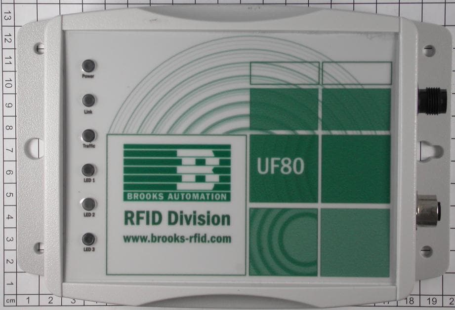
N5GUF80
Jul 01, 2012RFID UHF Reader
Equipment Class
DSS - Part 15 Spread Spectrum Transmitter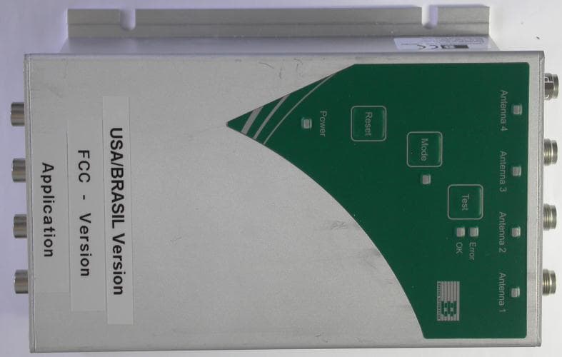
N5GUF70
May 30, 2012RFID UHF Reader
Equipment Class
DSS - Part 15 Spread Spectrum Transmitter
N5GHF5
Mar 09, 2006Inductive Tag Reader
Equipment Class
DXT - Part 15 Low Power Transceiver, Rx Verified