N5ZDN464Digital Voice Recorder
Dyne Telecom Co Ltd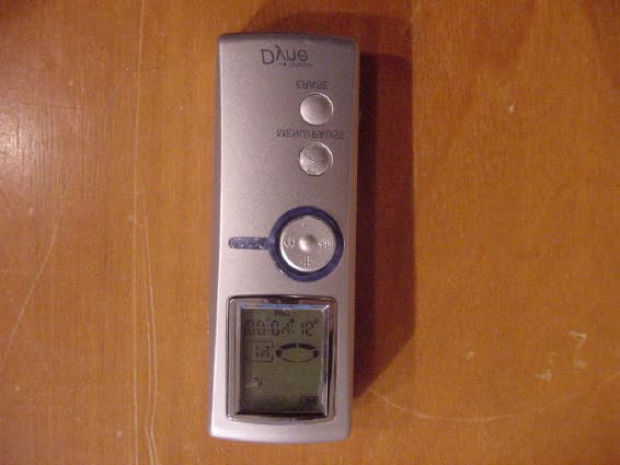
Click to zoom
Application Details
- Equipment Class
- JBP - Part 15 Class B Computing Device Peripheral
- Date of Grant
- Oct 20, 2002
- Application Purpose
- Original Equipment
- Date of Application
- Oct 20, 2002
- Equipment Note
- Digital Voice Recorder
- Company
- Dyne Telecom Co Ltd
- Country
- South Korea
Documents & Files
Document Text
Text extracted from the exhibit documents filed with the FCC. Open a document above to read the original.
Users Manual
Note : This equipment has been tested and found to comply with the limits for a Class B digital device, pursuant to part 15 of the FCC Rules. These limits are designed to provide reasonable protection against harmful interference in a residential installation. This equipment generates, uses and can radiate radio frequency energy and, if not installed and used in accordance with the instructions, may cause harmful interference to radio communications. However, there is no guarantee that interference will not occur in a particular installation. If this equipment does cause harmful interference to radio or television reception, which can be determined by turning the equipment off and on, the user is encouraged to try to correct the interference by one or more of the following measures : - Reorient or relocate the receiving antenna. - Increase the separation between the equipment and receiver. - Connect the equipment into an outlet on a circuit different from that to which the receiver is connected. - Consult the dealer or an experienced radio/TV technician for help.
Test Report
EMI COMPLIANCE REPORT Emission of electromagnetic disturbance Test Report No. : ERI-FCC-0145 Equipment : DIGITAL VOICE RECORDER & MP3- PLAYER Name of basic model : DN4128 Family model : DN432, DN464, MVP-108, MVP-108+ Manufacturer : DYNE TELECOM CO., LTD. Applicant : DYNE TELECOM CO., LTD. Tested date : 2002.10.10 Issued date : 2002.10. 14 Receipted date of EUT:2002. 10. 12 Test results : PASS Test Standards : FCC Part 15 Subpart B (Class B) Test Procedure and Items : - AC Power line Conducted emissions measurement : ANSI C63.4-1992 - Radiated emissions measurement : ANSI C63.4-1992 Tested by: SE-JIN, O Approved by: SANG- KYU, LEE The results in this report apply only to the sample tested. This test report shall not be reproduced except in full, without the written approval of ERI Laboratory. ERIELECTROMAGNETIC RESEARCH INSTITUTE CONTENTS 1. CLIENT INFORMATION............................................................................................... 3 2. LABORATORY INFORMATION................................................................................... 3 3. EQUIPMENT UNDER TEST INFORMATION(EUT) ............................................. 3 3.1 Identification of the EUT.................................................................................... 3 3.2 Additional information about the EUT............................................................. 4 3.3 Peripheral equipment.......................................................................................... 4 4. CONTINUOUS DISTURBANCE VOLTAGE, MAIN TERMINAL........................... 5 4.1 Operating environment....................................................................................... 5 4.2 Test set-up and test procedures........................................................................ 5 4.3 Test instrument...................................................................................................... 6 4.4 Test results.............................................................................................................. 6 5. RADIATED DISTURBANCE : 30MHz – 1000MHz ......................................... 9 5.1 Operating environment....................................................................................... 9 5.2 Test set-up ............................................................................................................ 9 5.3 Test conditions...................................................................................................... 10 5.4 Test instrument..................................................................................................... 10 5.5 Test results............................................................................................................. 10 6. PRODURCT PHOTOGRAPHS................................................................................. 11 6.1 Front Photograph of EUT..................................................................................... 11 6.2 Rear Photograph of EUT...................................................................................... 11 6.3 Front Photograph of mainboard 1.................................................................... 12 6.4 Rear Photograph of mainboard 1....................................................................... 12 6.5 Front Photograph of mainboard 2...................................................................... 13 6.6 Rear Photograph of mainboard 2....................................................................... 13 ERIELECTROMAGNETIC RESEARCH INSTITUTE 1. CLIENT INFORMATION The EUT has been tested by request of : Company : DYNE TELECOM CO., LTD. Address : #3F CHUNGYONG B/D 1123-1, KWANYANG-2DONG, DONGAN-GU, ANYANG-CITY, KYUNGKI-DO, KOREA Name of contact : HAK-REA HONG Telephone : +82-31-422-3481 Facsimile : +82-31-422-3483 2. LABORATORY INFORMATION The 10m semi-anechoic chamber and/or EMC facilities are used for these testing. These facilities were accredited by KOLAS, EK, MIC of Korea and FCC. Address ELECTROMAGNETIC RESEARCH INSTITUTE. 66-6, JEIL-RI, YANGJI-MYUN, YOUNGIN-CITY, KYUNGGI-DO, KOREA Telephone No. : +82-31-336-1186~7 Facsimile No. : +82-31-336-1184 Registered No. KOLAS : 111 EK : J MIC : KR0030 FCC Filing No. : 302567 3. EQUIPMENT UNDER TEST INFORMATION(EUT) 3.1 Identification of the EUT Type of equipment : DIGITAL VOICE RECORDER & MP3-PLAYER Model name : DN4128 Brand name : N/A Manufacturer : DYNE TELECOM CO., LTD. Address :#3F CHUNGYONG B/D 1123-1, KWANYANG-2DONG, DONGAN-GU, ANYANG-CITY, KYUNGKI-DO, KOREA Telephone : +82-31-422-3481 Facsimile : +82-31-422-3483 Country of origin : KOREA Rating : DC 1.5V ERIELECTROMAGNETIC RESEARCH INSTITUTE 3.2 Additional information about the EUT Family Models List: Basic Model Variant Model Memory Differential point DN4128 - 128M Memory DN432 32M Memory DN464 64M Memory MVP-108 - Buyer request model name DN4128 MVP-108+ - Buyer request model name 3.3 Peripheral equipment Defined as equipment needed for correct operation of the EUT. Description Model No Manufacture Serial No DIGITAL VOICE RECORDER&MP3- PLAYER DN4128 DYNE TELECOM CO., LTD N/A NOTE PC CM2080 LG electronic Co., Ltd. 5Y17JNZ9R892 AC/DC adaptor - Delta electronics Co., Ltd MJD0124008510 Mic N/A N/A N/A Earphone N/A N/A N/A Printer 930C HP CN13V1B1SZ ERIELECTROMAGNETIC RESEARCH INSTITUTE 4. CONTINUOUS DISTURBANCE VOLTAGE, MAIN TERMINAL : Frequency range 0.15 MHz to 30 MHz 4.1 Operating environment Temperature : 25.0 Relative Humidity : 65.0 % 4.2 Test set-up and test procedures RECEIVER EUT NOTE PC Printer AC/DC adaptor Mic LISN LISN earphone ERIELECTROMAGNETIC RESEARCH INSTITUTE The mains terminal disturbance voltage was measured with the equipment under test(EUT) in a shield room. The EUT was connected to an artificial mains network(LISN) placed on the floor. The EUT was placed on non-metallic table 0.8m above the metallic, grounded floor. The distance to other metallic surface was at least 0.8m. Amplitude measure…
Text truncated - open the document above for the full version.
Contact Information
Applicant
S. Y. Lee(President)
82-343-22-3481.3482Fax: 82-343-22-3483
Test Firm
EMC Compliance LTDMin Seok Chung
Technical Specifications
| # | Rule Parts | Frequency Range | Power Output |
|---|---|---|---|
| 1 | 15B | - | - |
Other Applications from Dyne Telecom Co Ltd
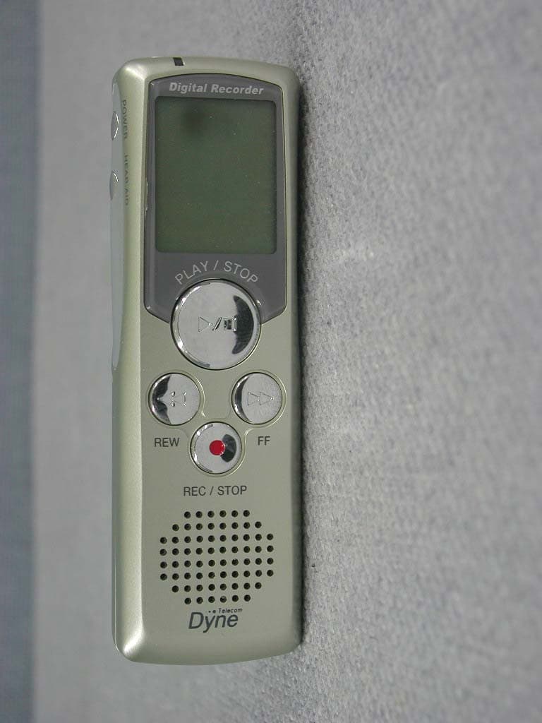
N5ZDN308
Nov 28, 2002Digital Voice Recorder
Equipment Class
CYY - Communications Receiver used w/Pt 15 Transmitter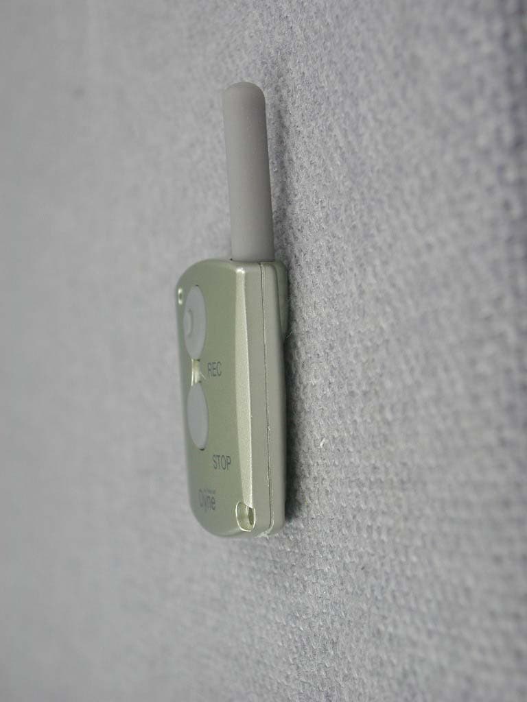
N5ZDN308R
Nov 28, 2002UHF Wireless Remote Controller
Equipment Class
DSC - Part 15 Security/Remote Control Transmitter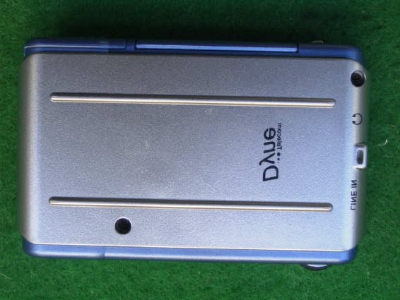
N5ZDN5128
Sep 26, 2002Digital Audio Player
Equipment Class
JBP - Part 15 Class B Computing Device Peripheral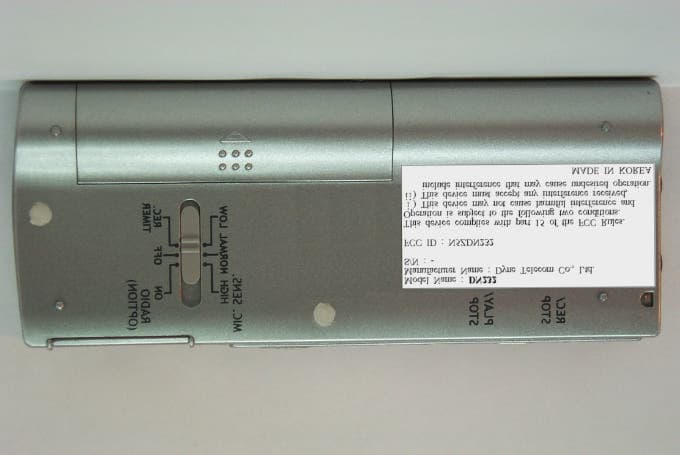
N5ZDN232
May 03, 2001Digital Voice Recorder
Equipment Class
JBP - Part 15 Class B Computing Device Peripheral
N5ZDT-311
Sep 28, 1998Numeric Radio Paging Receiver
Equipment Class
CXX - Communications Rcvr for use w/ licensed Tx and CBs