N5ZDN5128Digital Audio Player
Dyne Telecom Co Ltd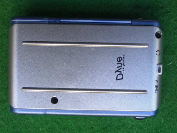
Click to zoom
Application Details
- Equipment Class
- JBP - Part 15 Class B Computing Device Peripheral
- Date of Grant
- Sep 26, 2002
- Application Purpose
- Original Equipment
- Date of Application
- Sep 26, 2002
- Equipment Note
- Digital Audio Player
- Company
- Dyne Telecom Co Ltd
- Country
- South Korea
Documents & Files
Document Text
Text extracted from the exhibit documents filed with the FCC. Open a document above to read the original.
Users Manual
Note : This equipment has been tested and found to comply with the limits for a Class B digital device, pursuant to part 15 of the FCC Rules. These limits are designed to provide reasonable protection against harmful interference in a residential installation. This equipment generates, uses and can radiate radio frequency energy and, if not installed and used in accordance with the instructions, may cause harmful interference to radio communications. However, there is no guarantee that interference will not occur in a particular installation. If this equipment does cause harmful interference to radio or television reception, which can be determined by turning the equipment off and on, the user is encouraged to try to correct the interference by one or more of the following measures : - Reorient or relocate the receiving antenna. - Increase the separation between the equipment and receiver. - Connect the equipment into an outlet on a circuit different from that to which the receiver is connected. - Consult the dealer or an experienced radio/TV technician for help.
ID Label/Location Info
Note : This equipment has been tested and found to comply with the limits for a Class B digital device, pursuant to part 15 of the FCC Rules. These limits are designed to provide reasonable protection against harmful interference in a residential installation. This equipment generates, uses and can radiate radio frequency energy and, if not installed and used in accordance with the instructions, may cause harmful interference to radio communications. However, there is no guarantee that interference will not occur in a particular installation. If this equipment does cause harmful interference to radio or television reception, which can be determined by turning the equipment off and on, the user is encouraged to try to correct the interference by one or more of the following measures : - Reorient or relocate the receiving antenna. - Increase the separation between the equipment and receiver. - Connect the equipment into an outlet on a circuit different from that to which the receiver is connected. - Consult the dealer or an experienced radio/TV technician for help.
Test Report
ERI Electromagnetic research institute 66-6, JEIL-RI, YANGJI-MYUN, YOUNGIN-CITY, KYUNGGI-DO, KOREA TEL: 82 31 336 1186 FAX : 82 31 336 1184 homepage : www.eri.re.kr ReportNo.:ERI-FCC-0141 Page : 1 of 15 EMI TEST REPORT Test report No.: ERI-FCC-0141 Type of equipment: MP3 PLAYER Model name: DN5128 Applicant: DYNE TELECOM CO., LTD. Test standards: FCC Part 15 Subpart B (Class B) Test Procedure and Items : - AC Power line Conducted emissions measurement: ANSI C63.4-1992 - Radiated emissions measurement: ANSI C63.4-1992 Test result : Pass This equipment has been tested to comply with the requirements of FCC rules and regulations Part 15 Subpart B unintentional radiators. The results in this report apply only to the sample tested. This test report shall not be reproduced except in full, without the written approval of ERI laboratory. Date of test: 2002. 9. 79. 11 Issued date: 2002. 9. 11 Tested by : Approved by: SEJIN, O SANG-KYU, LEE ERI Electromagnetic research institute 66-6, JEIL-RI, YANGJI-MYUN, YOUNGIN-CITY, KYUNGGI-DO, KOREA TEL: 82 31 336 1186 FAX : 82 31 336 1184 homepage : www.eri.re.kr ReportNo.:ERI-FCC-0141 Page : 2 of 15 Contents 1. Client information 2. Laboratory information 3. Test system configuration 3.1 Operation environment 3.2 Measurement uncertainty 3.3 Sample calculation 4. Description of EUT 4.1 Product description 4.2 Peripherals 4.3 Used cables 4.4 E.U.T. test configuration 4.5 Operating conditions 5. Test results 5.1 Conducted emission 5.1.1 Measurement procedure 5.1.2 Used equipments 5.1.3 Measurement uncertainty 5.1.4 Test data 5.1.5 Test result ERI Electromagnetic research institute 66-6, JEIL-RI, YANGJI-MYUN, YOUNGIN-CITY, KYUNGGI-DO, KOREA TEL: 82 31 336 1186 FAX : 82 31 336 1184 homepage : www.eri.re.kr ReportNo.:ERI-FCC-0141 Page : 3 of 15 5.2 Radiated emission 5.2.1 Measurement procedure 5.2.2 Used equipments 5.2.3 Measurement uncertainty 5.2.4 Test data(Upload mode) 5.2.5 Test data(Download mode) 5.2.6 Test result 6. Photographs Conducted emission test [front, rear] Radiated emission test [front, rear] Attached : Conducted emission graph ERI Electromagnetic research institute 66-6, JEIL-RI, YANGJI-MYUN, YOUNGIN-CITY, KYUNGGI-DO, KOREA TEL: 82 31 336 1186 FAX : 82 31 336 1184 homepage : www.eri.re.kr ReportNo.:ERI-FCC-0141 Page : 4 of 15 1. Client information Applicant/Manufacturer: DYNE TELECOM CO., LTD. Address : #3F Chungyong B/D 1123-1, Kwanyang-2dong, dongan-gu, anyang-city, Kyungki-do, Korea Telephone number: 82-31-422-3481 Facsimile number: 82-31-422-3483 Contact person: HAK-REA HONG 2. Laboratory information Address The open area test site and EMC facilities are used for these testing. This facility was accredited by KOLAS, EK of Korea, MIC, FCC. EMC RESEARCH INSTITUTE . 66-6, JEIL-RI, YANGJI-MYUN, YOUNGIN-CITY, KYUNGGI-DO, KOREA Telephone Number : 82- 31- 336- 1186 Facsimile Number : 82- 31- 336 -1184 KOLAS No.: 111 EK: J MIC: KR0030 FCC Filing No.: 302567 ERI Electromagnetic research institute 66-6, JEIL-RI, YANGJI-MYUN, YOUNGIN-CITY, KYUNGGI-DO, KOREA TEL: 82 31 336 1186 FAX : 82 31 336 1184 homepage : www.eri.re.kr ReportNo.:ERI-FCC-0141 Page : 5 of 15 3. TEST SYSTEM CONFIGURATION 3.1 Operation environment TemperatureHumidityPressure 10m Chamber : 22.0C 57 %- Shielded room :24.0C58 %998hPa 3.2 Measurement Uncertainty All measurements involve certain levels of uncertainties, specifically in field of EMC. The factors contributing to uncertainties are test receiver, Cable loss, antenna factor calibration, Antenna directivity, antenna factor variation with height, antenna phase center variation, antenna Frequency interpolation, measurement distance variation, site imperfection, mismatch, and system repeatability. Based on NIS 80,81, The measurement uncertainty level with a 95% confidence level were applied. ERI Electromagnetic research institute 66-6, JEIL-RI, YANGJI-MYUN, YOUNGIN-CITY, KYUNGGI-DO, KOREA TEL: 82 31 336 1186 FAX : 82 31 336 1184 homepage : www.eri.re.kr ReportNo.:ERI-FCC-0141 Page : 6 of 15 3.3 Sample calculation Conducted emission The field strength is calculated by adding the LISN factor, cable loss from the measured reading. The sample calculation is as follows : FS = MR + LF + CL MR = Meter Reading LF = LISN Factor CL = Cable Loss If MR is 30dB, LISN Factor 1dB, CL 1dB The result (MR) is 30 + 1 + 1 = 32dBuV Radiated emission The field strength is calculated by adding the antenna Factor, cable loss and, Antenna pad subtracting the amplifier gain from the measured reading. The sample calculation is as follows : FS = MR + AF + CL + AT -AG MR = Meter Reading AF = Antenna Factor CL = Cable Loss AT = Antenna Pad AG=Amplifier Gain If MR is 30dB, AF 12dB, CL 5dB, AP 10dB, AG 35dB The result (MR) is 30 + 12 + 5 + 10 –35 = 22dBuV/m ERI Electromagnetic research institute 66-6, JEIL-RI, YANGJI-MYUN, YOUNGIN-CITY, KYUNGGI-DO, KOREA TEL: 82 31 336 1186 FAX : 82 31 336 1184 homepage : www.eri.re.kr ReportNo.:ERI-FCC-0141 Page : 7 of 15 4. Description of EUT 4.1 Product description Type of product :MP3 PLAYER Basic model No. :DN5128 Serial No. :N/A Electric rating :DC 3V General description : This EUT(Equipment under test) is MP3 Player. 4.2 Peripherals DescriptionManufacturerModel / Part #Serial No MP3 PLAYER DYNE TELECOM CO., LTD DN5128N/A NOTE PCLG electronic Co., Ltd.CM20805Y17JNZ9R892 AC/DC adaptor Delta electronics Co., Ltd Keyboard Samsung electro- machinics Co., Ltd. SDM4510UH4M015720 MouseN/AM0SXUBN/A Mic&earphoneN/AN/AN/A PrinterHPC6427ACN13V1B1SZ SpeakerFengshin electronicsCAMAC G7N/A 4.3 Used cables Cable typeShield Length (meters) Connector Connection point 1 Connection point 2 USB PORTYES1.0USBNOTE PC- EarphoneNO1.0P-JackEarphone- ERI Electromagnetic research institute 66-6, JEIL-RI, YANGJI-MYUN, YOUNGIN-CITY, KYUNGGI-DO, KOREA TEL: 82 31 336 1186 FAX : 82 31 336 1184 homepage : www.eri.re.kr ReportNo.:ERI-FCC-0141 Page : 8 of 15 4.4 EUT Test configuration 4.5 Operating conditions Operating : Data up&download mode - The system was c…
Text truncated - open the document above for the full version.
Contact Information
Applicant
S. Y. Lee(President)
82-343-22-3481.3482Fax: 82-343-22-3483
Test Firm
EMC Compliance LTDMin Seok Chung
Technical Specifications
| # | Rule Parts | Frequency Range | Power Output |
|---|---|---|---|
| 1 | 15B | - | - |
Other Applications from Dyne Telecom Co Ltd
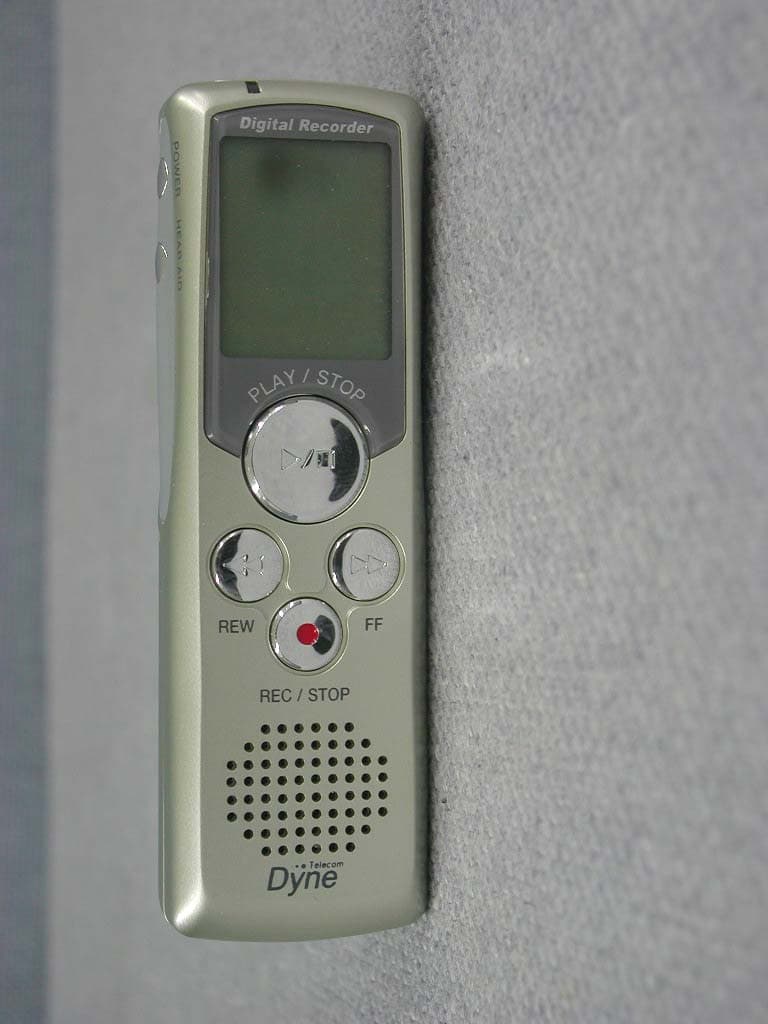
N5ZDN308
Nov 28, 2002Digital Voice Recorder
Equipment Class
CYY - Communications Receiver used w/Pt 15 Transmitter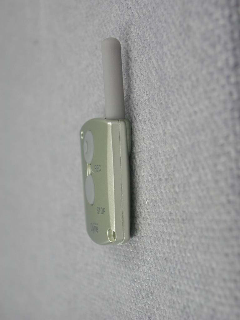
N5ZDN308R
Nov 28, 2002UHF Wireless Remote Controller
Equipment Class
DSC - Part 15 Security/Remote Control Transmitter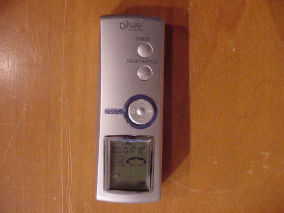
N5ZDN464
Oct 20, 2002Digital Voice Recorder
Equipment Class
JBP - Part 15 Class B Computing Device Peripheral
N5ZDN232
May 03, 2001Digital Voice Recorder
Equipment Class
JBP - Part 15 Class B Computing Device Peripheral
N5ZDT-311
Sep 28, 1998Numeric Radio Paging Receiver
Equipment Class
CXX - Communications Rcvr for use w/ licensed Tx and CBs