N73-AP60-BLEAXON BLE
Mine Site Technologies Pty Ltd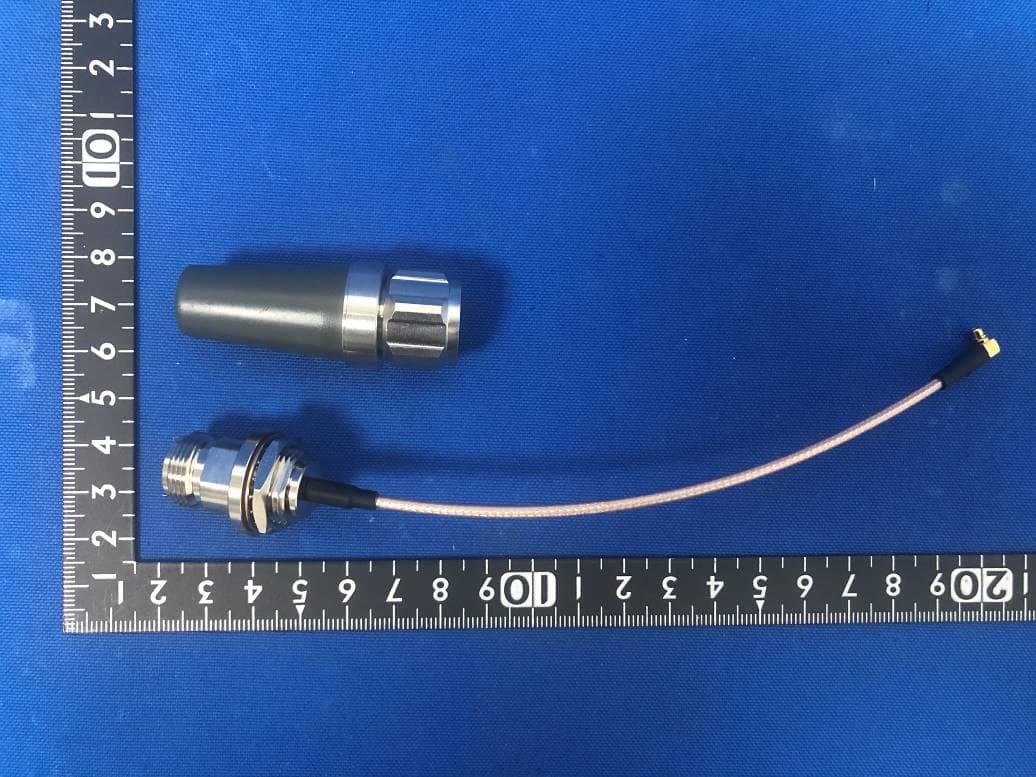
Click to zoom
Application Details
- Equipment Class
- DTS - Digital Transmission System
- Date of Grant
- Aug 11, 2020
- Application Purpose
- Original Equipment
- Date of Application
- Aug 10, 2020
- Equipment Note
- AXON BLE
- Frequency Range
- 2402.00000000 - 2480.00000000
- Country
- Australia
Documents & Files
Document Text
Text extracted from the exhibit documents filed with the FCC. Open a document above to read the original.
Users Manual
AXON AIR BLE Module User Manual Features: Bluetooth® 5, IEEE 802.15.4-2006, 2.4 GHz transceiver. Buttons and LEDs for user interaction. I/O interface and NFC interface for user to expand. Support backup battery power supply. Support SEGGER J-Link debug interface. CE/FCC/IC compliant. Hardware Specifications: Bluetooth 5.0 Low Energy Standard: IEEE 802.15.4 Frequency Band: 2.402GHz to 2.480GHz CH: 0~39 Frequency Spacing: 2MHz Supported data rates: 1 Mbps Power: DC 3.3V from mini PCIe interface (backup battery 225mAh) Receiver Sensitivity: -95 dBm sensitivity in 1 Mbps Bluetooth® low energy mode Antenna: MMCX connector *2 CPU: ARM® Cortex®-M4 32-bit processor with FPU, 64 MHz Working Temperature: -20 ~ 70°C Storage Humidity : 10% ~ 90% Software Specifications: RF Work Mode: TX: Bypass Mode/Low Power Mode/High Power Mode RX: Bypass Mode/LNA Mode Antenna Select: Can select ANT1/ANT2/Sleep Mode Beacon Transmit Configuration: Configure iBeacon/Eddy stone / customized Beacon. Beacon Scan Scan and receive BLE beacons. Specification Table Item Description Type BLE Module Size(mm) 30 mm * 51mm Weight(g) 9.7 g Control Port Mini PCIe Power Supply DC 3.3V Antenna 2 external antennas Bluetooth Port Bluetooth 5.0 Low Energy User interface J-Link/NFC/IO Expansion Battery Capacity(mAh) 225 mAh Working Temperature ‐20 C ~ 70 °C BLE Module Outward Number Description 1 Antenna Connecters 2 J-Link Interface 3 Button 4 Battery 5 Mini PCIe Interface 6 IO Expansion Interface 7 NFC Interface 8 LED Final Product Sample Example Federal Communications Commission (FCC) Interference Statement This equipment has been tested and found to comply with the limits for a Class B digital device, pursuant to Part15 of the FCC Rules. These limits are designed to provide reasonable protection against harmful interference in a residential installation. This equipment generate, uses and can radiate radio frequency energy and, if not installed and used in accordance with the instructions, may cause harmful interference to radio communications. However, there is no guarantee that interference will not occur in a particular installation. If this equipment does cause harmful interference to radio or television reception, which can be determined by turning the equipment off and on, the user is encouraged to try to correct the interference by one of the following measures: ⚫ Reorient or relocate the receiving antenna. ⚫ Increase the separation between the equipment and receiver. ⚫ Connect the equipment into an outlet on a circuit different from that to which the receiver is connected. ⚫ Consult the dealer or an experienced radio/TV technician for help. This device complies with Part 15 of the FCC Rules. Operation is subject to the following two conditions: (1) This device may not cause harmful interference, and (2) this device must accept any interference received, including interference that may cause undesired operation. FCC Caution: Any changes or modifications not expressly approved by the party responsible for compliance could void the user's authority to operate this equipment. RF exposure warning This equipment complies with FCC radiation exposure limits set forth for an uncontrolled environment. Industry Canada (IC) CAN ICES-3 (B)/NMB-3(B) This device complies with Industry Canada’s licence-exempt RSSs. Operation is subject to the following two conditions: (1) This device may not cause harmful interference, and (2) this device must accept any interference received, including interference that may cause undesired operation. Cet appareil est conforme à la norme RSS d'Industrie Canada. Son fonctionnementestsujet aux deux conditions suivantes: (1) ledispositif ne doit pas produire de brouillagepréjudiciable, et (2) cedispositifdoit accepter tout brouillagereçu, y compris un brouillage susceptible de provoquer un fonctionnementindésirable. IMPORTANT NOTE: Radiation Exposure Statement: This equipment complies with IC radiation exposure limits set forth for an uncontrolled environment. This equipment should be installed and operated with minimum distance 20cm between the radiator and your body. Déclarationd'exposition aux radiations: Cetéquipementestconforme aux limitesd'exposition aux rayonnements IC établies pour un environnement non contrôlé. Cetéquipementdoitêtreinstallé et utilisé avec un minimum de 20cm de distance entre la source de rayonnement et votre corps. Federal Communications Commission (FCC) Interference Statement THIS DEVICE COMPLIES WITH PART 15 OF THE FCC RULES. OPERATION IS SUBJECT TO THE FOLLOWING TWO CONDITIONS: (1) THIS DEVICE MAY NOT CAUSE HARMFUL INTERFERENCE, AND (2) THIS DEVICE MUST ACCEPT ANY INTERFERENCE RECEIVED, INCLUDING INTERFERENCE THAT MAY CAUSE UNDESIRED OPERATION. NOTE: THE GRANTEE IS NOT RESPONSIBLE FOR ANY CHANGES OR MODIFICATIONS NOT EXPRESSLY APPROVED BY THE PARTY RESPONSIBLE FOR COMPLIANCE. SUCH MODIFICATIONS COULD VOID THE USER’S AUTHORITY TO OPERATE THE EQUIPMENT. For additional hosts other than the specific host originally granted with a limited module, a Class II permissive change is required on the module grant to register the additional host as a specific host also approved with the module. The host must meet the necessary requirements to satisfy the module limiting conditions: shield and power supply regulation. The module is limited to OEM installation ONLY. The OEM integrator is responsible for ensuring the end user has no manual instructions to remove or install module. Regulatory Module Integration Instructions This module has been granted modular approval for mobile applications. OEM integrators for host products may use the module in their final products without additional FCC / IC (Industry Canada) certification if they meet the following conditions. Otherwise, additional FCC / IC approvals must be obtained. • The host product with the module installed must be evaluated for simultaneous transmission requirements. • The user manual for the host product must clearly indicate the ope…
Text truncated - open the document above for the full version.
Cover Letter(s)
Date: July 30, 2020 Mine Site Technologies Pty Ltd NORTH RYDE BC, P.O. Box 122, NSW, 1670, Australia Request for Modular/Limited Modular Approval Subject: Manufacrurer's Declaration for 181 -Modular Approval D -Split Modular Approval 0 -Limited Modular Approval 0 -Limited Split Modular Approval Confidentiality Request for: N73-AP60-BLE 8 Basic Requirements-FCC Part 15.2ll(a)(l) For Items Marked "NO(*)" the Limited Module Description Must be Filled Out on the Following Pages Modular Approval Requirement Requirement Met I. The modular transmitter must have its own RF shielding. This is intended to ensure that the module does not have to rely upon the hielding provided by the device into which it is installed in order for all modular transmitter emissions to comply with FCC limits. It is also intended to prevent coupling 181-YES 0-NO(*) between the RF circuitry of the module and any wires or circuits in the device into which the module is installed. Such coupling may result in non-compliant operation. The physical crystal and tuning capacitors may be located external to the shielded radio elements. 15.212(a)(l)(i) Details: This module does have its own RF shielding. 2. The modular transmitter must have butlercd modulation/data inp~ (if such inputs are provided) to ensure that the module will comply with FCC requirements under conditions of excessive data rates or i:8J-YES 0-NO(*) over-modulation. IS.212(a)(l)(ii) . Detailf: This module has buffered data inputs w~ich is integrated in main chip U2. 3. The modular transmitter must have its o\\n power su Jy_~gJllatiqg on the module. This is intended to ensure that the module will comply with FCC requirements regardless of the design of the power 1:8J -YES 0-NO(*) supplying circuitry in the device into which the module is installed. 15.212,{a)(l)(iii) Details: The module has its own power supply regulation U3. 4. The modular transmitter must compl~ with the antenna and transmission system requireme'l!J! of §§ 15.203, I S.204(b), IS.204(c), JS.212(a), and 2.929(b). The antenna must either be permanently attached or employ a " unique'' antenna coupler (at all connections between the module and the 1:8J -YES 0-NO(*) antenna, including the cable). The "professional installation" provision of§ 15.203 is not applicable to modules but can apply to limited modular approvals under paragraph 15.212(b). 15.212(a)(J)(iv) Details: The module complies with the antenna requirements. 5. The modular transmitter must be tested in a stand-alone conli uratim1, i.e ., the module must not be inside another device during testing. This is intended to demonstrate that the module is capable of complying with Part IS emission limits regardless oftlte device into which it is eventually installed. Unless the transmitter module will be battery powered, it must comply with the AC line conducted requirements found in Section 15.207. AC or DC power lines and data input/output lines connected to 181-YES 0-NO(*) the module must not contain ferrites, unless they will be marketed with the module (see Section 15.27(a)). The length ofthese lines shall be length typical of actual use or, ifthat length is unknown, at least I 0 centimeters to insure that there is no coupling between the case of the module and supporting equipment. Any accessories, peripherals, or support equipment connected to the module during testing shall be unmodified or commercially available (see Section 15.3l(i)). 15.212(a)(l)(v) Details: The module was tested in a stand-alone configuration. 070920-02b Mine Site Technologies Pty Ltd NORTH RYDF BC, P 0 Bo. 1 '22 N')W 1670, Australia Modular Approval Requirement 6. The modular transmitter must be labeled with its 0\\11 !-('( I D number, or use an electron display (see KDB Publication 784748). lfusing a permanently affixed label with its own FCC lD number, if the FCC lD is not visible when the module is installed inside another device, then the outside of the device into which the module is installed must also display a label referring to the enclosed module. This exterior label can use wording such as the following; "Contains Transmitter Module FCC 10; XYZMODEL I" or ··contains FCC lD: XYZMODEL I." Any similar wording that expresses the same meaning may be used. The Grantee may either provide such a label, an example of which must be included in the application for equipment authorization, or, must provide adequate instructions along with the module which explain this Requirement Met requirement. In the latter case, a copy of these instructions must be included in the application for 1:8:1 -YES 0 -NO(*) equipment authorization. lfthe modular transmitter uses an electronic display of the FCC identification number, the information must be readily accessible and visible on the modular transmitter or on the device in which it is installed. If the module is installed inside another device, then the outside of the device into which the module is installed must display a label referring to the enclosed module. This exterior label can use wording such as the following: "Contains FCC certified transmitter module(s)." Any similar wording that expresses the same meaning may be used. The user manual must include instructions on how to access the electronic display. A copy of these instructions must be included in the application for equipment authorization. 15.212(a)( I )(vi) Details: The module is labeled with its own FCC ID number and showed as required when installed inside another device. 7. The modular transmitter must comply with all specific rule or operating requirements applicable to the transmitter, including the conditions provided in the integration instructions by the gran . A copy of these instructions must be included in the application for equipment authorization. For example, there are very strict operational and timing requirements that must be met before a transmitter is authorized for operation under Section 15.231. For instance, data transmission is prohib…
Text truncated - open the document above for the full version.
External Photos
Report No.: 2006RSU024-UE 1 of 2 External Photograph (1) EUT Photo (2) EUT Photo Report No.: 2006RSU024-UE 2 of 2 (3) EUT Photo (4) EUT Photo
ID Label/Location Info
Label Location
Internal Photos
Report No.: 2006RSU024-UE 1 of 1 Internal Photograph (1) EUT Photo (2) EUT Photo
RF Exposure Info
MRT Technology (Suzhou) Co., Ltd Report No.: 2006RSU024-U2 Phone: +86-512-66308358 Report Version: V01 Web: www.mrt-cert.com Issue Date: 07-20-2020 Page Number: 1 of 11 RF Exposure Evaluation Declaration FCC ID: N73-AP60-BLE Applicant: Mine Site Technologies Pty Ltd Application Type: Certification Product: AXON BLE Model No.: A-AP60-200 Brand Name: MINE SITE TECHNOLOGIES FCC Classification: Digital Transmission System (DTS) Test Procedure(s): KDB 447498 D01v06 Test Date: July 20, 2020 Reviewed By: ( Kevin Guo ) Approved By: ( Robin Wu ) The test results relate only to the samples tested. The test results shown in the test report are traceable to the national/international standards through the calibration of the equipment and evaluated measurement uncertainty herein. The test report shall not be reproduced except in full without the written approval of MRT Technology (Suzhou) Co., Ltd. Report No.: 2006RSU024-U2 Page Number: 2 of 11 Revision History Report No. Version Description Issue Date Note 2006RSU024-U2 Rev. 01 Initial Report 07-20-2020 Valid Report No.: 2006RSU024-U2 Page Number: 3 of 11 CONTENTS Description Page General Information .................................................................................................................... 4 1. INTRODUCTION ................................................................................................................... 5 1.1. Scope .................................................................................................................................... 5 1.2. MRT Test Location .............................................................................................................. 5 2. PRODUCT INFORMATION ................................................................................................... 6 2.1. Equipment Description........................................................................................................ 6 2.2. Product Specification Subjective to this Report .............................................................. 6 2.3. Working Frequencies for this report ................................................................................. 6 2.4. Description of Available Antennas .................................................................................... 7 2.5. Description of Antenna RF Port ........................................................................................ 7 3. RF Exposure Evaluation ..................................................................................................... 8 3.1. Limits ..................................................................................................................................... 8 3.2. Test Procedure ..................................................................................................................... 9 3.3. Test Result of RF Exposure Evaluation ......................................................................... 10 Appendix A – EUT Photograph ................................................................................................. 11 Report No.: 2006RSU024-U2 Page Number: 4 of 11 General Information Applicant: Mine Site Technologies Pty Ltd Applicant Address: 113 Wicks Road, North Ryde, New South Wales, 2113, Australia Manufacturer: Mine Site Technologies China Co. Ltd. Manufacturer Address: 4th Floor, Building 1, No. 1413 Moganshan Road, Hangzhou, Zhejiang Province, 310011, China Test Site: MRT Technology (Suzhou) Co., Ltd Test Site Address: D8 Building, No.2 Tian’edang Rd., Wuzhong Economic Development Zone, Suzhou, China Test Facility / Accreditations Measurements were performed at MRT Laboratory located in Tian’edang Rd., Suzhou, China. MRT facility is a FCC registered (MRT Designation No. CN1166) test facility with the site description report on file and has met all the requirements specified in ANSI C63.4-2014. MRT facility is an IC registered (MRT Reg. No. 11384A-1) test laboratory with the site description on file at Industry Canada. MRT facility is a VCCI registered (R-20025, G-20034, C-20020, T-20020) test laboratory with the site description on file at VCCI Council. MRT Lab is accredited to ISO 17025 by the American Association for Laboratory Accreditation (A2LA) under the American Association for Laboratory Accreditation Program (A2LA Cert. No. 3628.01) in EMC, Telecommunications, Radio and SAR testing. Report No.: 2006RSU024-U2 Page Number: 5 of 11 1. INTRODUCTION 1.1. Scope Measurement and determination of electromagnetic emissions (EMC) of radio frequency devices including intentional and/or unintentional radiators for compliance with the technical rules and regulations of the Federal Communications Commission and the Innovation, Science and Economic Development Canada and Certification and Engineering Bureau. 1.2. MRT Test Location The map below shows the location of the MRT LABORATORY, its proximity to the Taihu Lake. These measurement tests were conducted at the MRT Technology (Suzhou) Co., Ltd. Facility located at D8 Building, No.2 Tian’edang Rd., Wuzhong Economic Development Zone, Suzhou, China. The measurement facility compliant with the test site requirements specified in ANSI C63.4-2014. Report No.: 2006RSU024-U2 Page Number: 6 of 11 2. PRODUCT INFORMATION 2.1. Equipment Description 2.2. Product Specification Subjective to this Report 2.3. Working Frequencies for this report Channel Frequency Channel Frequency Channel Frequency 00 2402 MHz 01 2404 MHz 02 2406 MHz 03 2408 MHz 04 2410 MHz 05 2412 MHz 06 2414 MHz 07 2416 MHz 08 2418 MHz 09 2420 MHz 10 2422 MHz 11 2424 MHz 12 2426 MHz 13 2428 MHz 14 2430 MHz 15 2432 MHz 16 2434 MHz 17 2436 MHz 18 2438 MHz 19 2440 MHz 20 2442 MHz 21 2444 MHz 22 2446 MHz 23 2448 MHz 24 2450 MHz 25 2452 MHz 26 2454 MHz 27 2456 MHz 28 2458 MHz 29 2460 MHz 30 2462 MHz 31 2464 MHz 32 2466 MHz 33 2468 MHz 34 2470 MHz 35 2472 MHz 36 2474 MHz 37 2476 MHz 38 2478 MHz 39 2480 MHz -- -- -- -- Product Name: AXON BLE M…
Text truncated - open the document above for the full version.
Test Report
MRT Technology (Suzhou) Co., Ltd Report No.: 2006RSU024-U1 Phone: +86-512-66308358 Report Version: V01 Web: www.mrt-cert.com Issue Date: 07-30-2020 1 of 70 FCC ID: N73-AP60-BLE IC: 7449B-AP60BLE Applicant: Mine Site Technologies Pty Ltd Application Type: Certification Product: AXON BLE Model No.: A-AP60-200 Brand Name: MINE SITE TECHNOLOGIES FCC Classification: Digital Transmission System (DTS) FCC Rule Part(s): Part 15 Subpart C (Section 15.247) ISED Rule(s): RSS-247 Issue 2, RSS-Gen Issue 5 Test Procedure(s): ANSI C63.10-2013 Test Date: June 11 ~ July 30, 2020 Reviewed By: ( Kevin Guo ) Approved By: ( Robin Wu ) MEASUREMENT REPORT FCC PART 15.247 / ISED RSS-247 Bluetooth-LE The test results relate only to the samples tested. This equipment has been shown to be capable of compliance with the applicable technical standards as indicated in the measurement report and was tested in accordance with the measurement procedures specified in ANSI C63.10-2013. Test results reported herein relate only to the item(s) tested. The test report shall not be reproduced except in full without the written approval of MRT Technology (Suzhou) Co., Ltd. Report No.: 2006RSU024-U1 2 of 70 Revision History Report No. Version Description Issue Date Note 2006RSU024-U1 Rev. 01 Initial Report 07-30-2020 Valid Report No.: 2006RSU024-U1 3 of 70 CONTENTS Description Page 1. INTRODUCTION ..................................................................................................................... 6 1.1. Scope ........................................................................................................................... 6 1.2. MRT Test Location ....................................................................................................... 6 2. PRODUCT INFORMATION ..................................................................................................... 7 2.1. Feature of Equipment under Test ................................................................................. 7 2.2. Product Specification Subjective to this Report ............................................................. 7 2.3. Working Frequencies for this report .............................................................................. 7 2.4. Description of Available Antennas ................................................................................ 8 2.5. Description of Antenna RF Port .................................................................................... 8 2.6. Test Mode .................................................................................................................... 8 2.7. Configuration of Test System ........................................................................................ 9 2.8. Test System Details ...................................................................................................... 9 2.9. Test Software ............................................................................................................... 9 2.10. EMI Suppression Device(s)/Modifications ..................................................................... 9 2.11. Labeling Requirements ............................................................................................... 10 3. DESCRIPTION OF TEST ....................................................................................................... 11 3.1. Evaluation Procedure .................................................................................................. 11 3.2. AC Line Conducted Emissions .................................................................................... 11 3.3. Radiated Emissions .................................................................................................... 12 4. ANTENNA REQUIREMENTS ................................................................................................ 13 5. TEST EQUIPMENT CALIBRATION DATE ............................................................................ 14 6. MEASUREMENT UNCERTAINTY ......................................................................................... 16 7. TEST RESULT ...................................................................................................................... 17 7.1. Summary .................................................................................................................... 17 7.2. Occupied Bandwidth Measurement ............................................................................ 18 7.2.1. Test Limit ................................................................................................................ 18 7.2.2. Test Procedure used ............................................................................................... 18 7.2.3. Test Setting ............................................................................................................. 18 7.2.4. Test Setup ............................................................................................................... 19 7.2.5. Test Result .............................................................................................................. 20 7.3. Output Power Measurement ....................................................................................... 22 7.3.1. Test Limit ................................................................................................................ 22 7.3.2. Test Procedure Used .............................................................................................. 22 Report No.: 2006RSU024-U1 4 of 70 7.3.3. Test Setting ............................................................................................................. 22 7.3.4. Test Setup ............................................................................................................... 23 7.3.5. Test Result .............................................................................................................. 24 7.4. Power S…
Text truncated - open the document above for the full version.
Test Setup Photos
Report No.: 2006RSU024-UT 1 of 3 Test Setup Photograph Description: Front View Conducted Emission Test Setup for Power Port Description: Back View Conducted Emission Test Setup for Power Port Report No.: 2006RSU024-UT 2 of 3 Description: Radiated Emission Test Setup for below 1GHz Description: Radiated Emission Test Setup for above 1GHz Report No.: 2006RSU024-UT 3 of 3 Description: Conducted Test Setup
Contact Information
Applicant
Vadim Parfenov(Chief Technology Officer)
Technical Contact
MRT Technology (Suzhou) Co., LtdRobin Wu
[email protected]86-512-66308358
D8 Building, Youxin Industrial Park, · Suzhou · China
Non-Technical Contact
MRT Technology (Suzhou) Co., LtdRobin Wu
[email protected]86-512-66308358
Test Firm
MRT Technology (Suzhou) Co., Ltd.Mr. Marlin Chen
[email protected]+86-512-66308358
Technical Specifications
| # | Rule Parts | Frequency Range | Power Output |
|---|---|---|---|
| 1 | 15C | 2.40 GHz - 2.48 GHz | 4.10 mW |
Other Applications from Mine Site Technologies Pty Ltd

N73-UT33
Apr 10, 2021UT33 Tag
Equipment Class
DTS - Digital Transmission System
N73-WRN-BLE
Sep 17, 2020WRN BLE
Equipment Class
DTS - Digital Transmission System
N73-MP70G2
Jan 26, 2016Mine Phone
Equipment Class
DTS - Digital Transmission System
N73-EX09
Oct 22, 2015Exciter
Equipment Class
DCD - Part 15 Low Power Transmitter Below 1705 kHz
N73-ET33
Jun 11, 2015ET33 Tag
Equipment Class
DTS - Digital Transmission System