N7NAC750GSM PCS1900 PCMCIA Card
Sierra Wireless, ULC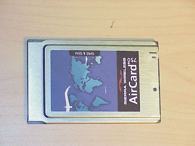
Click to zoom
Application Details
- Equipment Class
- PCB - PCS Licensed Transmitter
- Date of Grant
- May 02, 2002
- Application Purpose
- Original Equipment
- Date of Application
- Nov 20, 2001
- Equipment Note
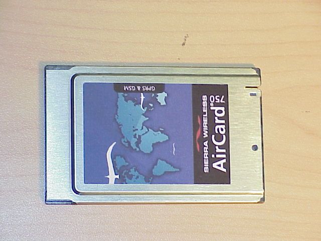
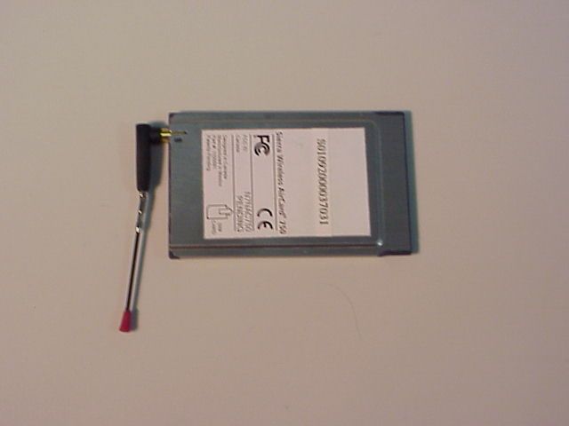
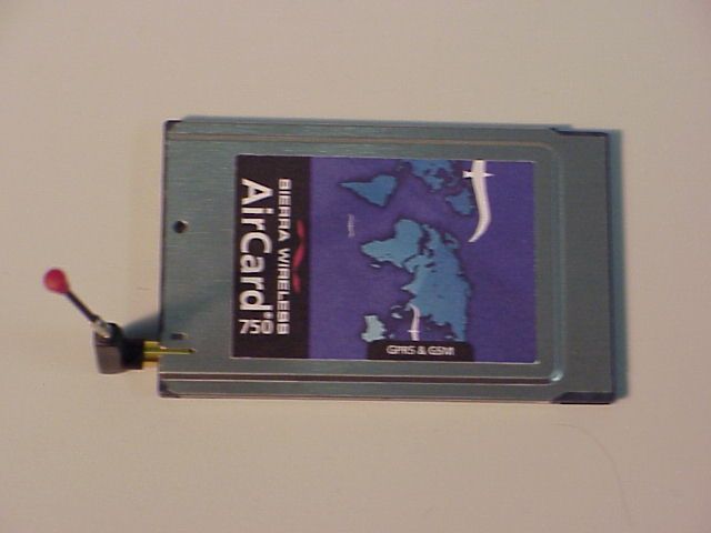
- GSM PCS1900 PCMCIA Card
- Frequency Range
- 1850.20000000 - 1909.80000000
- Company
- Sierra Wireless, ULC
- Country
- Canada
Documents & Files
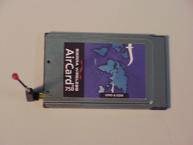
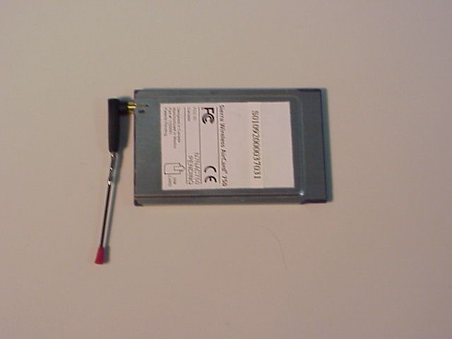
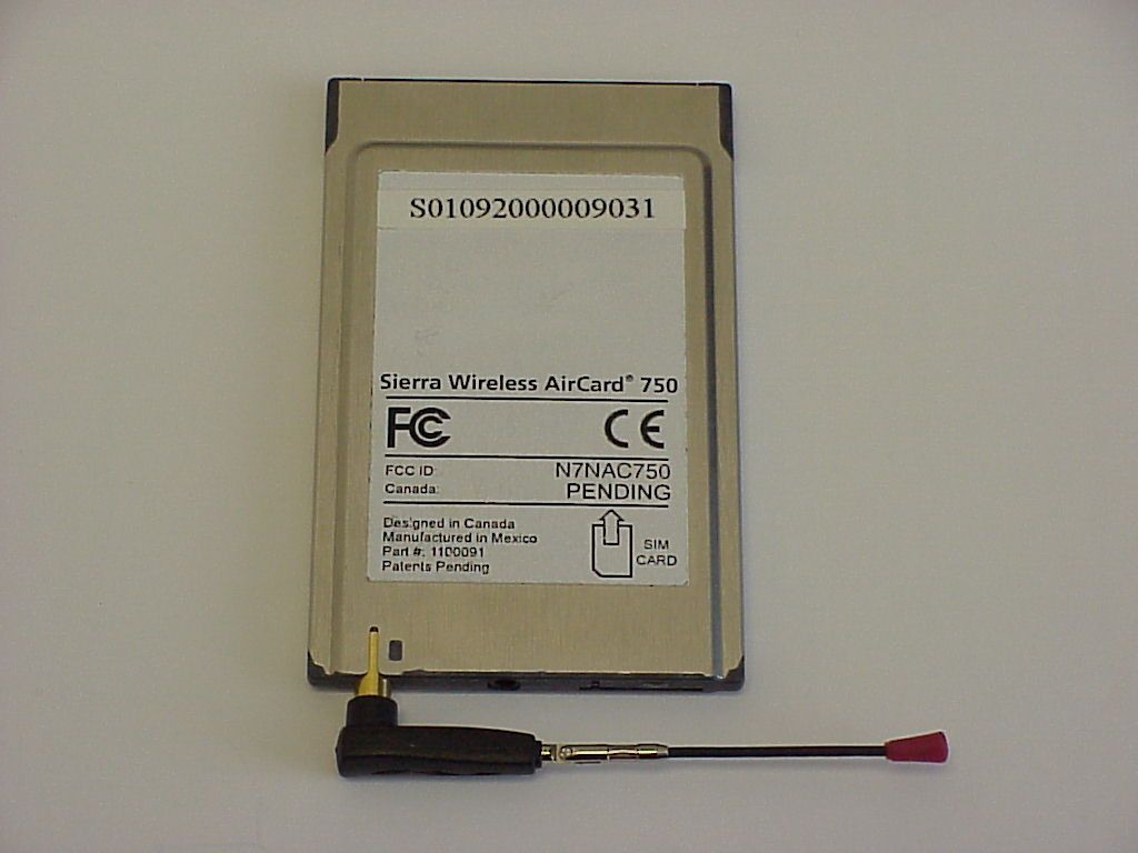
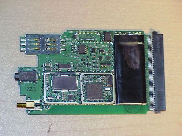
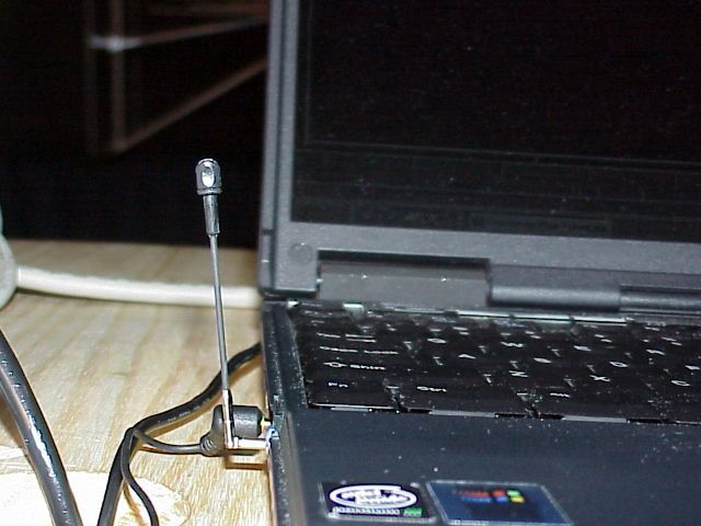
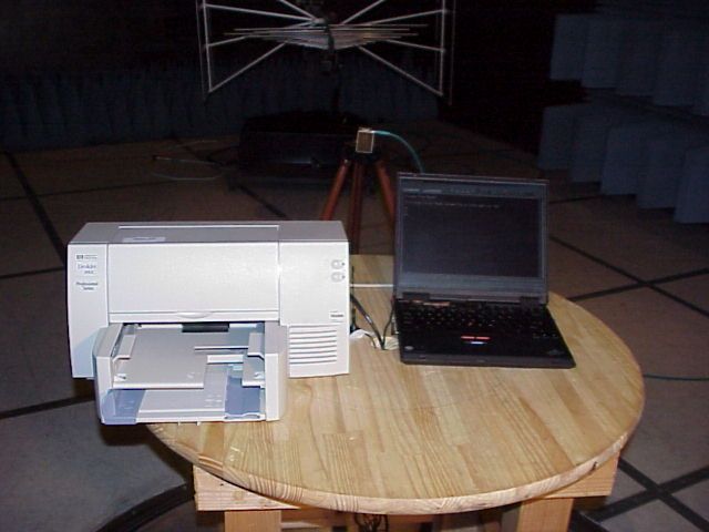
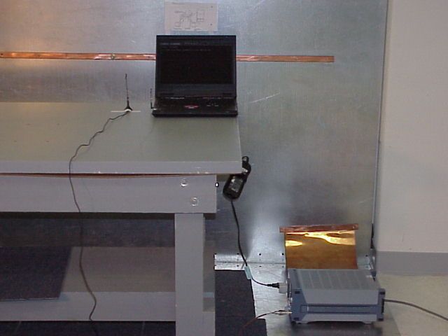
Document Text
Text extracted from the exhibit documents filed with the FCC. Open a document above to read the original.
Users Manual
AirCard ® 710/750 Wireless Network Card Installation Guide 2130135 Rev 1.3 Table of Contents Rev. 1.3 Mar.02iii Important NoticeBecause of the nature of wireless communications, trans- mission and reception of data can never be guaranteed. Data may be delayed, corrupted (i.e., have errors) or be totally lost. Although significant delays or losses of data are rare when wireless devices such as the Sierra Wireless network card are used in a normal manner with a well-constructed network, the Sierra Wireless network card should not be used in situations where failure to transmit or receive data could result in damage of any kind to the user or any other party, including but not limited to personal injury, death, or loss of property. Sierra Wireless, Inc. accepts no responsibility for damages of any kind resulting from delays or errors in data transmitted or received using the Sierra Wireless network card, or for failure of the Sierra Wireless network card to transmit or receive such data. Safety and HazardsDo not operate the Sierra Wireless AirCard ® 710/750 wireless network card in areas where blasting is in progress, where explosive atmospheres may be present, near medical equipment, life support equipment, or any equipment which may be susceptible to any form of radio interference. In such areas, the Sierra Wireless network card MUST BE POWERED OFF. The Sierra Wireless network card can transmit signals that could interfere with this equipment. Do not operate the Sierra Wireless network card in any aircraft, whether the aircraft is on the ground or in flight. In aircraft, the Sierra Wireless network card MUST BE POWERED OFF. When operating, the Sierra Wireless network card can transmit signals that could interfere with various onboard systems. Note: Some airlines may permit the use of cellular phones while the aircraft is on the ground and the door is open. Sierra Wireless network cards may be used at this time. The driver or operator of any vehicle should not operate the Sierra Wireless network card while in control of a vehicle. Doing so will detract from the driver or operator's control and operation of that vehicle. In some states and provinces, operating such communications devices while in control of a vehicle is an offence. FCC RF Exposure Information In August 1996 the Federal Communications Commission (FCC) of the United States with its action in Report and Order FCC 96-326 adopted an updated safety standard for human exposure to radio frequency (RF) electromagnetic energy emitted by FCC regulated transmitters. Those guidelines are AirCard 710/750 Wireless Network Card Installation Guide iv2130135 consistent with the safety standard previously set by both U.S. and international standards bodies. The design of this wireless network card complies with the FCC guidelines and these international standards. Use only the supplied or an approved antenna. Unauthorized antennas, modifications, or attachments could impair call quality, damage the phone, or result in violation of FCC regulations. This device is approved for use in typical laptop PCs only. To comply with FCC RF exposure requirements the AirCard 710/750 PCS GSM modem card must be operated with a minimum separation distance of 2.5 cm (1 inch) between the user/nearby persons and the antenna. Always place the antenna in the upright position (oriented vertically) when using the AirCard 710/750 in a laptop computer. For more information about RF exposure, please visit the FCC web site at www.fcc.gov . Limitation of Liability The information in this manual is subject to change without notice and does not represent a commitment on the part of Sierra Wireless, Inc. SIERRA WIRELESS, INC. SPECIFICALLY DISCLAIMS LIABILITY FOR ANY AND ALL DIRECT, INDIRECT, SPECIAL, GENERAL, INCIDENTAL, CONSE- QUENTIAL, PUNITIVE OR EXEMPLARY DAMAGES INCLUDING, BUT NOT LIMITED TO, LOSS OF PROFITS OR REVENUE OR ANTICIPATED PROFITS OR REVENUE ARISING OUT OF THE USE OR INABILITY TO USE ANY SIERRA WIRELESS, INC. PRODUCT, EVEN IF SIERRA WIRELESS, INC. HAS BEEN ADVISED OF THE POSSI- BILITY OF SUCH DAMAGES OR THEY ARE FORESEEABLE OR FOR CLAIMS BY ANY THIRD PARTY. PatentsPortions of this product are covered by some or all of the following US patents: 6339405, D452496, D452495, 6327154, D442170, 6199168, 6191741, 6169884, D416857, 5929815, 5890057, 5878234, 5847553, 5845216, 5748449, 5682602, 5629960, 5617106, D372701, D372248, 5515013, D367062 and other patents pend- ing. Copyright©2002 Sierra Wireless, Inc. All rights reserved. Table of Contents Rev. 1.3 Mar.02v TrademarksAirCard ® and Heart of the Wireless Machine ® are registered trademarks of Sierra Wireless, Inc. Sierra Wireless, the Sierra Wireless logo, the red wave design, the red-tipped antenna, and Watcher are trademarks of Sierra Wireless, Inc. Other trademarks are the property of the respective owners. All product specifications are subject to change without notice. AirCard 710/750 Wireless Network Card Installation Guide vi2130135 Rev 1.3 Mar.02vii Table of Contents Introducing the AirCard® 710/750 Network Card . . . . . . . . . . . . . .1 About the AirCard 710/750 wireless network card . . . . . . . . . . . . . . . . . . . . . . . 1 Supported computer platforms and wireless networks . . . . . . . . . . . . . . . . . . 1 Care and maintenance of your AirCard . . . . . . . . . . . . . . . . . . . . . . . . . . . . . . . . 2 Getting Started . . . . . . . . . . . . . . . . . . . . . . . . . . . . . . . . . . . . . . . . . . . .5 Information you must get from your service provider . . . . . . . . . . . . . . . . . . . . 5 SIM card overview. . . . . . . . . . . . . . . . . . . . . . . . . . . . . . . . . . . . . . . . . . . . . . . . . . 6 Inserting a SIM card . . . . . . . . . . . . . . . . . . . . . . . . . . . . . . . . . . . . . . . . . . . . 6 Removing a SIM card . . . . . . . . . . . . . . . . . . . . . . . . . . . . . . . . . . . . . . . . . . . 6 Installation on Notebook PCs . . . . . . . . . . . . .…
Text truncated - open the document above for the full version.
Attestation Statements
FCC ID N7NAC750 EA753377 Statement The AC750 PCS wireless PCMCIA card can operate in both voice and data mode . The tests were done only in one mode since the RF performance and transmission is totally identical for both modes. The unit transmits in the assigned time slots independent if it is data or voice mode. (see also remarks in page 7 of the test report) The test data are valid for both modes. The antenna is removable. Only one antenna is used for this device. The antenna connector is a special custom designed connector for Sierra Wireless. Tuning range 1850 – 1910 MHz for the uplink 1930 - 1990 MHz for the downlink Maximum output power The maximum output power in section 1.5 of the test report shows the wrong value. The measured power of the devices is documented in the relevant sections (EIRP and conducted power) of the test report. Max peak power: 32.54 dBm + 1.8W Lothar Schmidt Technical Manager EMC/Radio
Attestation Statements
EMC (The answers are integrated in the text behind the questions) 1) For conducted tests please provide: Test setup diagrams and procedures. Please address how the burst nature of this device was accounted for in testing. The Analyzer was triggered by the burst and measured the peak value in max hold position over several sweeps until the value didn’t change anymore. The test setup please see document “CONFIGURATION BLOCK DIAGRAM”. The offset for the conducted measurements includes Attenuator (10dB), cable and power splitter. A results table providing numerical results . See table “NUMERICAL SPURIOUS EMISSIONS” New data to replace the plots for 30-1000 MHZ such as on page 35 of the test report. BW of 1 MHZ is required, per CFR section 24.238 (b). See Document “spurious and band edge results” which shows the pages to be replaced of the original report Description of how the equipment was controlled during testing to assure maximum power transmission and proper modulation. The device was controlled by the base station simulator (CMD 55). The power level was set to the highest level. Please discuss the difference between peak and average power reported on page 7 of the test report. The variation between 28 and 18 dBm is unexpected. The Average power was re-measured using a power meter and a thermocouple probe see document “power measurements”. 2) For radiated tests please provide: Test setup diagrams and procedures. Please address how the burst nature of this device was accounted for in testing. The Analyzer was triggered by the burst and measured the peak value in max hold position over several sweeps until the value didn’t change anymore. A table providing numerical results . See table “NUMERICAL SPURIOUS EMISSIONS” Please note that the substitution method must be used for any values within 20 dB of the limit. We use the substitution method for all the measurements see description in the test report page 8 of the test report. We extended this method for the whole range of spurious emissions (26.5 GHz) we are operating at the moment recently. During the procedure to measure the “reference path loss” it was verified that we are within ± 2dB due to interpolation errors. Measurement results within ± 3 dB are substituted at the single frequency Additional details how the plots on pages 14-27 of the test report were made. Include a discussion of what steps were taken to measure peak emissions. Include details of scan time. The plots on page 14, 17, 20 and 24 are replaced by the document “30_1grad”. All the measurements were done using the R&S measurement system with the relevant software. The sweeps are implemented using basic setting from the spurious measurement software according PTCRB requirements. This method is used to make sure that the sweep times are set to catch in minimum one Burst during the sweep time in transmit and idle mode Clarification if all frequencies were investigated or only harmonics. The procedure on page 12 states "... measurements of the harmonics of the transmit frequency through the 10th harmonic were measured....". This suggests nonharmonic frequencies were not investigated. Please clarify. This sentence specify only the frequency range spurious are measured. In this range all frequencies are investigated. Description of how the equipment was controlled during testing to assure maximum power transmission and proper modulation. The device was controlled by the base station simulator (CMD 55). The power level was set to the highest level. 3) Details of the emissions designator and justification for necessary bandwidth. This information was not located. 271KGXW 4) Regarding your answer to question 4 of correspondence 21816. The frequency range stated appears to be the block frequency range as opposed to the tuning range of the equipment. Please clarify. Related to this please state the tuned frequencies for the band edge plots on test report pages 41 and 41 of 52. Frequency range using mid frequency of the lowest and highest channel is: 1850.2 – 1909.8MHz The band edge measurement were repeated with the relevant 5 kHz bandwidth and for the low and high channel of the lowest and the highest block and additionally on one mid frequency block see document “spurious and band edge results” SAR answers provided by the SAR test lab ITS (the questions are attached in the next page) 1. Correction was made in the report. 2. Changes in the Manual as recommended (see attached modified manual section 3. The device was tested in GPRS mode. In this mode it uses four time slots to transmit data (instead of one time slot in the GSM (voice) mode). In this data transmission mode voice is not active but the average power has the highest value. For this reason this mode was used. 4. The device was set to transmit the maximum power with the highest Duty Cycle. See answer 3. 5. The device was set to transmit four time slots. This is why instead of Crest Factor of 8 (usually used for GSM) the Crest Factor of 2 was setup. It is mentioned on page 18 of the test report. 6. The test was performed with the Probe Conversion Factor provided by the manufacturer (SPIAG). The manufacturer provided the Conversion Factor defined in the head tissue liquid. As per additional info from the SPIAG, the difference between the Conversion Factors for Head and Body might be in the range of 3% - 11%, and the Conversion Factor for Body is higher. With higher Conversion Factor, the SAR is less. So, the SAR numbers in the report is a worst case. The Supplement C to OET 65 requires the Tissue Dielectric Parameters for Body for 1800-2000 MHz as: epsilon = 53.3, sigma = 1.52. The test were performed with the liquid with the following parameters: epsilon = 54.9, sigma = 1.40 for f=1850 MHz epsilon = 54.8, sigma = 1.44 for f=1880 MHz epsilon = 54.8, sigma = 1.48 for f=1910 MHz In the middle of the range (1910 MHz) the parameters only 3% differ from the required; sigma decreases slightly (to 8%) at 1850 MHz. As the highest…
Text truncated - open the document above for the full version.
Attestation Statements
Answers to FCC questions for the Sierra Wireless AirCard 750: FCC ID: N7NAC 750 Request # 22318 A) Please provide a table summarizing the mode of operation (GSM or GPRS) used, and method for device control for each test made in the EMC and SAR reports. A 14 March telephone discussion with Mr. Lothar Schmidt suggested that different configurations were used. Please provide any supporting details that are not contained in the test report. Please note: SAR tests were repeated at a different lab (CCS). Please refer to these later results. The rationale for switching SAR labs is mentioned later in this document. Power Measurement Mode of OperationMethod of Device Control EMC Peak Power GSM CMD55 base station simulator EMC Avg. Power GPRS(4 time slots) continuous Tx (AT commands) SAR Avg. Power GPRS(4 time slots) continuous Tx (AT commands) All FCC part 24 tests were conducted in GSM mode, except the average output power measurements that were done in GPRS mode. In GSM mode, the R&S CMD55 base station simulator controlled t he mobile. The average output power measurements were all done in GPRS mode so that a comparison could be made between the EMC and SAR power measurements. GPRS mode required the use of customer AT commands to enable the mobile to transmit continuously at maximum power in 4 time slots. This mode of operation was necessary since base station simulators do not support multi-slot operation at this time. The AirCard 750 is a Class 12 GPRS multi-slot mobile, which can transmit on a maximum of 4 time slots. Operating in 4 time slots ensured that the SAR measurements were done at the highest power level possible. B) Regarding your answer to question 2 and the above reference phone call, it was stated that a sweep time of 5 ms was used for the 30-1000 MHZ plots on pages 14-27 of the test report. Please provide new data with at least 2 second sweep times while using a peak hold mode. Please perform this test with the rotating table moving at no more than 10 degrees in two seconds. The requested results have been uploaded. The slight difference in output spectrum compared to previous results is entirely due to the change in host laptop used, not the mobile itself. C) Regarding your answer to SAR question 2. Please provide a modified users manual statement. The statement "The intended use of this device is within typical laptop computers " can be easily misunderstood. Please use a more direct statement such as. This device as been tested for compliance with FCC RF exposure limits in a typical laptop computer such as the one reported in the grant application. This device is only authorized to be used in such a typical laptop computer." A new version of the Install Guide has been uploaded. (See page iv for User Warnings and page 27 for regulatory information). Please note this Install Guide replaces all previous User Manuals and is a common guide for both the AirCard 750 (triband) and the AirCard 710 (single band – PCS). The AirCard 710 has already received FCC approval. SAR D) Regarding your answer to SAR question 6, please provide more comprehensive analysis justifying use of the chosen probe calibration. Please provide details of the "additional info from the SPIAG" referenced in your answer. The FCC's understanding of the SPEAG system does not support the estimations made. Please provide an updated uncertainty budget accounting for any extra uncertainty associated with this probe conversion factor. Additionally, if possible please provide a print out of the liquid's dielectric properties as measured by your equipment for frequencies from 1800 to 1900 MHz. Please see the answer to E below. E) Regarding your answer to question 9. In order to validate your hypothesis please provide new SAR data at the worst case setup and frequency using both paper and foam as a stand. Questions D and E forced a review of SAR testing carried out by ITS in November. The following was noted: 1) The body conversion factor used by ITS was incorrect. 2) The probe used in November was damaged and could not be reused. 3) The original liquids’ dielectric properties were close to FCC limits. 4) Repeating an informal test with a foam stand instead of paper resulted in reduced SAR values. Overall, the original SAR values could not be repeated. The new informal values (not recorded) appeared to be about half of the SAR values measured in November. For this reason, the customer, Sierra Wireless, decided to repeat the entire SAR test at CCS in Morgan Hill, CA. A Sierra Wireless representative was present for this SAR test to ensure test conditions were tightly controlled and the problems mentioned above were not repeated. The CCS results confirmed that the SAR values are well within acceptable limits. Also the CCS results broadly agree with the later (but informal) SAR readings observed at ITS. Note: The testing was done with the antenna parallel to the phantom. This is the worst-case separation distance of antenna to body. The Sierra Wireless Install Guide mentions that the antenna only be used in a vertically oriented position (see page iv) and page 2 for a diagram (Figure 1-1). Lothar Schmidt Technical Manager EMC/Radio
Attestation Statements
ctc_gn_01_00.doc (General);5/3/02 Page 1 of 1 CETECOM Inc. 411 Dixon Landing Road Milpitas, CA 95035 U.S.A. Phone: + 1 408 586 6200 Fax: + 1 408 586 6299 e-mail: [email protected] URL: www.cetecom.com Statement The measurement results reported in SAR report as max. output power of 25.1 dBm is the average value and corresponds to 28.57 dBm peak output power. These values corresponds to the values reported in the file “power measurement results modified” of the FCC submittals. Lothar Schmidt CETECOM Inc.
Cover Letter(s)
November 19, 2001 Federal Communications Commission Equipment Authorization Branch 7435 Oakland Mills Road Columbia, MD 21046 Re: Sierra Wireless Inc. FCC ID: N7NAC750 FCC Part 24 Certification Request for Confidentiality Gentlemen: In accordance with 0.459 of CFR 47, Sierra Wireless Inc. hereby requests confidentiality of the block diagram, circuit diagrams, circuit description, operational description, parts list, and tune-up procedure attachments for the subject application. These documents contain detailed system and equipment description and related information about the product in which Sierra Wireless Inc. considers to be proprietary, confidential, and a custom design and, otherwise, would not release to the general public. Since this design is a basis from which future technological products will evolve, Sierra Wireless Inc. considers that this information would be of benefit to its competitors, and that the disclosure of the information in these documents would give competitors an unfair advantage in the market. Sincerely, Bill Andrews AirCard 710/750 Approvals Manager Sierra Wireless Inc.
Cover Letter(s)
Page 1 of 1 CETECO M Inc. 411 Dixon Landing Road Milpitas, CA 95035 U. S . A. Phone: + 1 408 586 6200 Fax: + 1 408 586 6299 e-mail: [email protected] UR L: www .c etec om.c om On request of the FCC a list “Exhibit list” indicating all documents which are valid and which are obsolete due to replacement by modified documents was uploaded to the EAS. All obsolete documents are marked with delete in the "description of Exhibit" column. Lothar Schmidt CETECOM Inc.
Cover Letter(s)
37 Matches Found For: FCC ID = N7NAC750 Query Results: View Attachment Exhibit TypeDescription of ExhibitDate Submitted to FCC Display Mode Attestation Statements Statements01/23/2002pdf Attestation Statements email answers02/14/2002pdf Attestation Statements Answers to req 2231803/26/2002pdf Cover Lettersauthorization letter11/27/2001pdf Cover Letters delete confidentiality request 11/27/2001 pdf Cover LettersConfidentiality request modified 01/23/2002pdf External Photostop view11/21/2001native External Photosbottom view11/21/2001native External Photoswith antenna11/27/2001native External PhotosTopview with antenna11/27/2001native ID Label/Location delete Info Label 11/27/2001 pdf ID Label/Location delete Info label photo 11/27/2001 pdf ID Label/Location Info ID Label photo12/10/2001native ID Label/Location Info photo of the PCMCIA card11/27/2001native Internal PhotosPCB top11/21/2001native Internal PhotosPCB bottom11/21/2001native RF Exposure InfoTest plots03/26/2002pdf RF Exposure Infoprobe data03/27/2002pdf RF Exposure InfoSAR report new03/26/2002pdf RF Exposure InfoSystem validation plots03/26/2002pdf RF Exposure InfoDipole validation kit data03/27/2002pdf Test Report delete SAR 11/30/2001 pdf Test ReportPart 24 report11/27/2001pdf Test Reportnumerical data02/14/2002pdf Page 1 of 2FCC OET Search Form 4/1/02http://gullfoss2.fcc.gov/cgi-bin/ws.exe/prod/oet/forms/reports/Search_Form.hts?mode=Edit&f... Mail your comments or suggestions (To: [email protected]) FCC - Federal Communications Commission - FCC OET Search Form Test ReportSweep time 2 sec03/26/2002pdf Test ReportFrequency stability11/27/2001pdf Test Repo rt delete modified SAR report 02/14/2002 pdf Test Reportradiated spurious modified02/14/2002pdf Test Reporttest configuration conducted02/14/2002pdf Test Reportsurious and band edge results02/14/2002pdf Test Reportpower measurement results modified 02/14/2002pdf Test Setup Photosconducted11/27/2001native Test Setup PhotosEUT FCC tests11/27/2001native Test Setup PhotosRadiated emissions11/27/2001native Users Manual delete user manual 11/27/2001 pdf Users Manualupdated version1303/26/2002pdf Users Manual delete modified page with laptop statement 02/14/2002 pdf End of Report. Page 2 of 2FCC OET Search Form 4/1/02http://gullfoss2.fcc.gov/cgi-bin/ws.exe/prod/oet/forms/reports/Search_Form.hts?mode=Edit&f...
Cover Letter(s)
38 Matches Found For: FCC ID = N7NAC750 Query Results: View Attachment Exhibit TypeDescription of ExhibitDate Submitted to FCC Display Mode Attestation Statements Statements01/23/2002pdf Attestation Statements email answers02/14/2002pdf Attestation Statements Answers to req 2231803/26/2002pdf Cover LettersExhibit list04/01/2002pdf Cover LettersExhibit list upload04/01/2002pdf Cover Lettersauthorization letter11/27/2001pdf Cover LettersConfidentiality request modified 01/23/2002pdf External Photostop view11/21/2001native External Photosbottom view11/21/2001native External Photoswith antenna11/27/2001native External PhotosTopview with antenna11/27/2001native ID Label/Location Info ID Label photo12/10/2001native ID Label/Location Info photo of the PCMCIA card11/27/2001native Internal PhotosPCB top11/21/2001native Internal Photos PCB bottom 11/21/2001 native RF Exposure Info delete Test plots 03/26/2002 pdf RF Exposure Info delete probe data 03/27/2002 pdf RF Exposure Infopover vs time04/29/2002pdf RF Exposure Info delete SAR report new 03/26/2002 pdf RF Exposure InfoTest report new04/29/2002pdf RF Exposure InfoDipol calibration04/29/2002pdf RF Exposure Infotimeslot definition04/29/2002pdf RF Exposure Info delete System validation plots 03/26/2002 pdf RF Exposure InfoProbe certification file04/29/2002pdf RF Exposure Info delete Dipole validation kit data 03/27/2002 pdf Page 1 of 2FCC OET Search Form 5/3/02https://gullfoss2.fcc.gov/cgi-bin/ws.exe/prod/oet/forms/reports/Search_Form.hts?mode=Edit&... Mail your comments or suggestions (To: [email protected]) FCC - Federal Communications Commission - FCC OET Search Form RF Exposure InfoTest report new additional positions 04/29/2002pdf Test ReportPart 24 report11/27/2001pdf Test Reportnumerical data02/14/2002pdf Test ReportSweep time 2 sec03/26/2002pdf Test ReportFrequency stability11/27/2001pdf Test Reportradiated spurious modified02/14/2002pdf Test Reporttest configuration conducted02/14/2002pdf Test Reportsurious and band edge results02/14/2002pdf Test Reportpower measurement results modified 02/14/2002pdf Test Setup Photosconducted11/27/2001native Test Setup PhotosEUT FCC tests11/27/2001native Test Setup PhotosRadiated emissions11/27/2001native Users Manualupdated version1303/26/2002pdf End of Report. Page 2 of 2FCC OET Search Form 5/3/02https://gullfoss2.fcc.gov/cgi-bin/ws.exe/prod/oet/forms/reports/Search_Form.hts?mode=Edit&...
RF Exposure Info
in accordance with the requirements of FCC Report and Order: ET Docket 93-62, and OET Bulletin 65 Supplement C for SIERRA WIRELESS TRI-BAND GSM/GPRS PC CARD (This report covers only GPRS mode SAR) MODEL: AirCard 750 FCC ID: N7NAC750 APRIL 18, 2002 REPORT NO: 02U1267-1 Prepared for SIERRA WIRELESS INC 13811 WIRELESS WAY RICHMOND BC CANADA, V5L 2N3 Prepared by COMPLIANCE CERTIFICATION SERVICES 561F MONTEREY ROAD, MORGAN HILL, CA 95037, USA TEL: (408) 463-0885 REPORT NO: 02U1267-1 DATE: April 18, 2002 FCC ID: N7NAC750 COMPLIANCE CERTIFICATION SERVICES Page: 2 of 19 This report shall not be reproduced except in full, without the written approval of CCS. This document may be altered or revised by Compliance Certification Services personnel only, and shall be noted in the revision section of the document. CERTIFICATE OF COMPLIANCE (SAR EVALUATION) Dates of Tests: April 18, 2002 Report No: 02U1267-1 APPLICANT: SIERRA WIRELESS INC 13811 WIRELESS WAY, RICHMOND BRITISH COLUMBIA V5L 2N3, CANADA TRADE NAME: Sierra Wireless AirCard 750 MODEL: AirCard 750 FCC ID: N7NAC750 DEVICE CATEGORY: MOBILE DEVICES EXPOSURE CATEGORY: GENERAL POPULATION/UNCONTROLLED EXPOSURE Test Sample is a: Production unit Operating Mode: Maximum continuous output Tx Frequency: 1850 – 1910 MHz Rx Frequency: 1930 – 1990 MHz Max. Output Power (Conducted): 25.1 dBm (1850.2 MHz) Max. SAR (1g): 0.0576 mW/g (1850.2 MHz) Application Type: Certification FCC Rule Part(s): § Part 24 (E) This wireless mobile device has been shown to be capable of compliance for localized specific absorption rate (SAR) for uncontrolled environment/general population exposure limits specified in ANSI/IEEE Std. C95.1-1992 and had been tested in accordance with the measurement procedures specified in FCC OET 65 Supplement C (released on 6/29/2001 see Test Report). I attest to the accuracy of data. All measurements reported herein were performed by me or were made under my supervision and are correct to the best of my knowledge and belief. I assume full responsibility for the completeness of these measurements and vouch for the qualifications of all persons taking them. Steve Cheng EMC Engineering Manager REPORT NO: 02U1267-1 DATE: April 18, 2002 FCC ID: N7NAC750 COMPLIANCE CERTIFICATION SERVICES Page: 3 of 19 This report shall not be reproduced except in full, without the written approval of CCS. This document may be altered or revised by Compliance Certification Services personnel only, and shall be noted in the revision section of the document. TABLE OF CONTENT 1. EUT DESCRIPTION..............................................................................................4 2. REQUIREMENTS FOR COMPLIANCE TESTING DEFINED BY THE FCC...............5 3. DOSIMETRIC ASSESSMENT SETUP....................................................................5 3.1. MEASUREMENT SYSTEM DIAGRAM.............................................................................................................6 3.2. SYSTEM COMPONENTS..................................................................................................................................7 3.3. EUT ARRANGEMENT......................................................................................................................................11 3.4. MEASUREMENT UNCERTAINTY...................................................................................................................12 4. EUT TUNE-UP PROCEDURE..............................................................................12 5. EVALUATION PROCEDURE..............................................................................13 5.1. SYSTEM ACCURACY VERIFICATION...........................................................................................................13 5.2. SAR EVALUATION PROCEDURE..................................................................................................................14 5.3. EXPOSURE LIMIT............................................................................................................................................14 6. MEASUREMENT RESULTS................................................................................15 7. EUT PHOTO......................................................................................................16 8. EQUIPMENTS LIST & CALIBRATION STATUS...................................................17 9. REFERENCES...................................................................................................18 10. ATTACHMENT...................................................................................................19 REPORT NO: 02U1267-1 DATE: April 18, 2002 FCC ID: N7NAC750 COMPLIANCE CERTIFICATION SERVICES Page: 4 of 19 This report shall not be reproduced except in full, without the written approval of CCS. This document may be altered or revised by Compliance Certification Services personnel only, and shall be noted in the revision section of the document. 1. EUT DESCRIPTION APPLICANT: SIERRA WIRELESS INC 1…
Text truncated - open the document above for the full version.
Contact Information
Applicant
Ying Wang(Director, Regulatory Compliance)
Technical Contact
CETECOM Inc.Lothar Schmidt
[email protected]408 586 6214
411 Dixon Landing Rd. · Milpitas, California · United States
Test Firm
Cetecom Inc.Lothar Schmidt
Technical Specifications
| # | Rule Parts | Frequency Range | Power Output | Emission | Tolerance |
|---|---|---|---|---|---|
| 1 | 24E | 1.85 GHz - 1.91 GHz | 1.79 W | 271GXW | 0.1000000000 ppm |
Other Applications from Sierra Wireless, ULC
N7NHL79E
Feb 23, 2026Radio Module
Equipment Class
PCB - PCS Licensed Transmitter
N7NEM92P
Sep 04, 2025Radio Module
Equipment Class
CBE - Citizens Band End User DevicesN7NHL79
Aug 15, 2024Module
Equipment Class
PCB - PCS Licensed Transmitter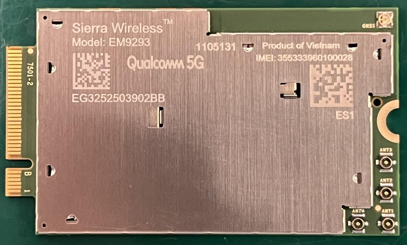
N7NEM92
Sep 26, 2023Radio Module
Equipment Class
CBE - Citizens Band End User Devices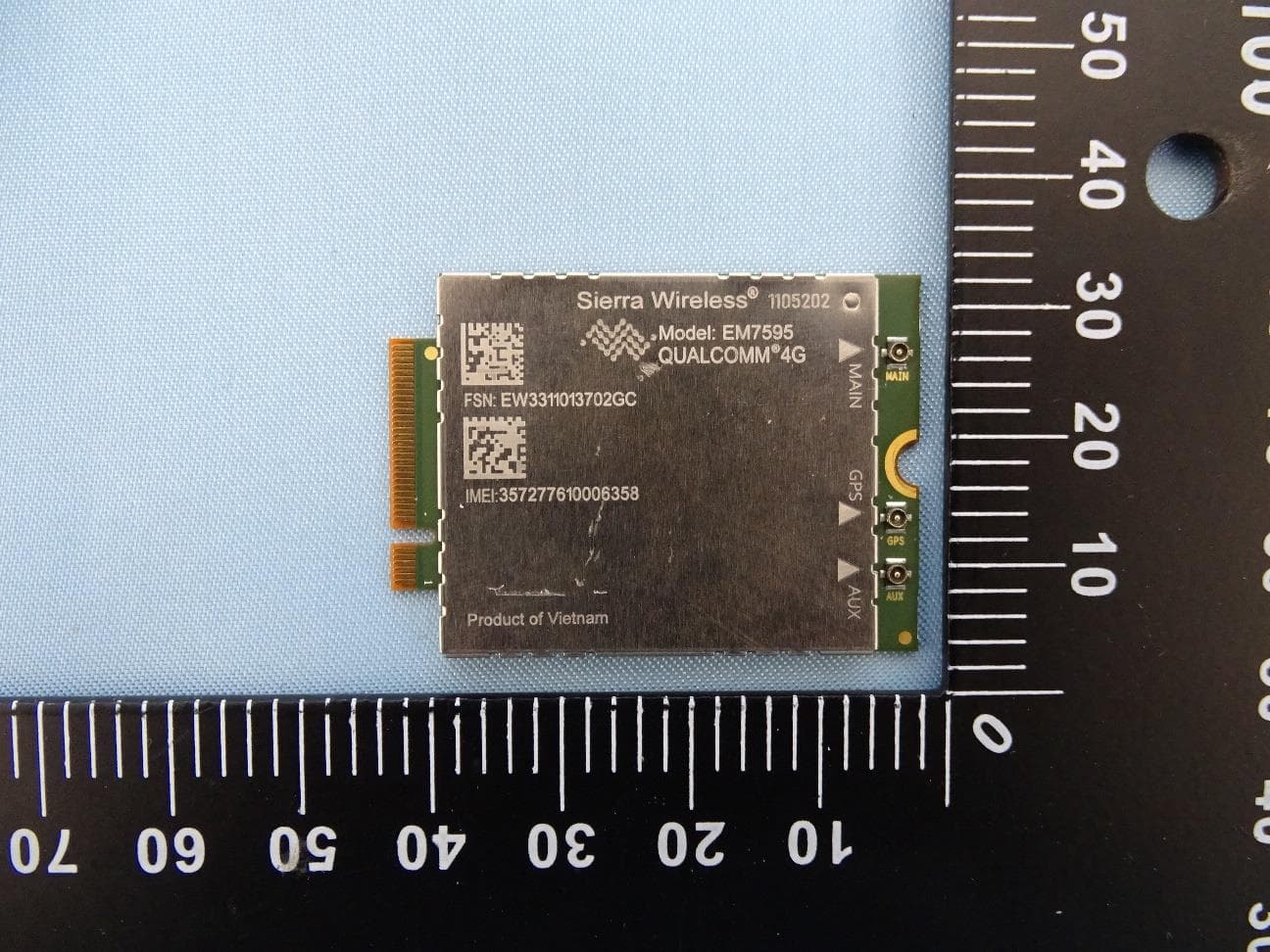
N7NEM75Y
Sep 10, 2023Radio Module
Equipment Class
PCB - PCS Licensed Transmitter