N7NAC755Tri-Band GSM/GPRS PC Card
Sierra Wireless, ULC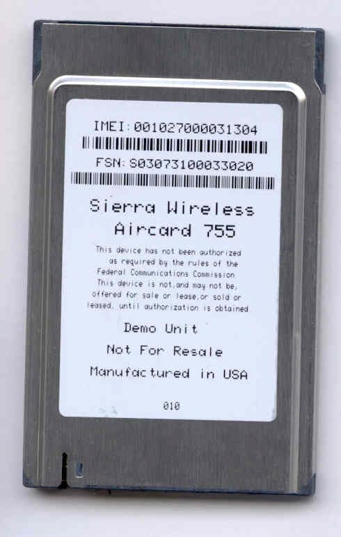
Click to zoom
Application Details
- Equipment Class
- PCB - PCS Licensed Transmitter
- Date of Grant
- Dec 18, 2003
- Application Purpose
- Original Equipment
- Date of Application
- Dec 18, 2003
- Equipment Note
- Tri-Band GSM/GPRS PC Card
- Frequency Range
- 1850.20000000 - 1909.80000000
- Company
- Sierra Wireless, ULC
- Country
- Canada
Documents & Files
Document Text
Text extracted from the exhibit documents filed with the FCC. Open a document above to read the original.
Users Manual
2130336 Rev D AirCard ® 755 Wireless Network Card Installation Guide Preface Rev D Dec.031 Important NoticeBecause of the nature of wireless communications, trans- mission and reception of data can never be guaranteed. Data may be delayed, corrupted (i.e., have errors) or be totally lost. Although significant delays or losses of data are rare when wireless devices such as the Sierra Wireless network card are used in a normal manner with a well-constructed network, the Sierra Wireless network card should not be used in situations where failure to transmit or receive data could result in damage of any kind to the user or any other party, including but not limited to personal injury, death, or loss of property. Sierra Wireless, Inc. and its affiliates accept no responsibility for damages of any kind resulting from delays or errors in data transmitted or received using the Sierra Wireless network card, or for failure of the Sierra Wireless network card to transmit or receive such data. Safety and HazardsDo not operate the Sierra Wireless AirCard ® wireless network card in areas where blasting is in progress, where explosive atmospheres may be present, near medical equipment, life support equipment, or any equipment which may be suscep- tible to any form of radio interference. In such areas, the Sierra Wireless network card MUST BE POWERED OFF. The Sierra Wireless network card can transmit signals that could interfere with this equipment. Do not operate the Sierra Wireless network card in any aircraft, whether the aircraft is on the ground or in flight. In aircraft, the Sierra Wireless network card MUST BE POWERED OFF. When operating, the Sierra Wireless network card can transmit signals that could interfere with various onboard systems. Note: Some airlines may permit the use of cellular phones while the aircraft is on the ground and the door is open. Sierra Wireless network cards may be used at this time. The driver or operator of any vehicle should not operate the Sierra Wireless network card while in control of a vehicle. Doing so will detract from the driver or operator's control and operation of that vehicle. In some states and provinces, operating such communications devices while in control of a vehicle is an offence. FCC RF Exposure Information In August 1996 the Federal Communications Commission (FCC) of the United States with its action in Report and Order FCC 96-326 adopted an updated safety standard for human exposure to radio frequency (RF) electromagnetic energy AirCard 755 Installation Guide 22130336 emitted by FCC regulated transmitters. Those guidelines are consistent with the safety standard previously set by both U.S. and international standards bodies. The design of this wireless network card complies with the FCC guidelines and these international standards. Use only the supplied or an approved antenna. Unauthorized antennas, modifications, or attachments could impair call quality, damage the phone, or result in violation of FCC regulations. To comply with FCC RF exposure requirements (US) the AirCard 755 GSM/GPRS modem card must be operated with a minimum separation distance of 2.5 cm (1 inch) between the user/nearby persons and the antenna. Always place the antenna in the upright position (oriented vertically) when using the AirCard 755 in a laptop computer. For more information about RF exposure, please visit the FCC web site at www.fcc.gov . Limitation of Liability The information in this manual is subject to change without notice and does not represent a commitment on the part of Sierra Wireless, Inc. or its affiliates. SIERRA WIRELESS, INC. AND ITS AFFILIATES SPECIFICALLY DISCLAIM LIABILITY FOR ANY AND ALL DIRECT, INDIRECT, SPECIAL, GENERAL, INCIDENTAL, CONSEQUENTIAL, PUNITIVE OR EXEMPLARY DAMAGES INCLUDING, BUT NOT LIMITED TO, LOSS OF PROFITS OR REVENUE OR ANTICI- PATED PROFITS OR REVENUE ARISING OUT OF THE USE OR INABILITY TO USE ANY SIERRA WIRELESS PRODUCT, EVEN IF SIERRA WIRELESS, INC.AND/OR ITS AFFILIATES HAVE BEEN ADVISED OF THE POSSIBILITY OF SUCH DAMAGES OR THEY ARE FORESEEABLE OR FOR CLAIMS BY ANY THIRD PARTY. NOTWITHSTANDING THE FOREGOING, IN NO EVENT SHALL SIERRA WIRELESS, INC. AND/OR ITS AFFILIATES’ AGGREGATE LIABILITY ARISING UNDER OR IN CONNECTION WITH THE SIERRA WIRELESS PRODUCT, REGARDLESS OF THE NUMBER OF EVENTS, OCCURRENCES OR CLAIMS GIVING RISE TO LIABILITY, BE IN EXCESS OF THE PRICE PAID BY THE PURCHASER FOR THE SIERRA WIRELESS PRODUCT. PatentsPortions of this product are covered by some or all of the following US patents: 5,515,0135,617,1065,629,9605,682,6025,748,449 5,845,2165,847,5535,878,2345,890,0575,929,815 6,169,8846,191,7416,199,1686,327,1546,339,405 D367,062D372,248D372,701D416,857D442,170 Preface Rev D Dec.033 D452,495D452,496and other patents pending. Copyright©2003 Sierra Wireless, Inc. All rights reserved. TrademarksAirCard ® and Heart of the Wireless Machine ® are registered trademarks of Sierra Wireless, Inc. Sierra Wireless, the Sierra Wireless logo, the red wave design, the red-tipped antenna, and Watcher are trademarks of Sierra Wireless, Inc. Other trademarks are the property of the respective owners. All product specifications are subject to change without notice. AirCard 755 Installation Guide 42130336 Rev D Dec.035 Table of Contents Introducing the AirCard® 755 Wireless Network Card . . . . . . . . .9 Supported operating systems . . . . . . . . . . . . . . . . . . . . . . . . . . . . . . . . . . . . 9 The AirCard as a network card . . . . . . . . . . . . . . . . . . . . . . . . . . . . . . . . . . . . 9 The AirCard as a mobile phone . . . . . . . . . . . . . . . . . . . . . . . . . . . . . . . . . . 10 Supported GSM frequency bands . . . . . . . . . . . . . . . . . . . . . . . . . . . . . . . . 10 Your account and coverage area . . . . . . . . . . . . . . . . . . . . . . . . . . . . . . . . . . . . 10 AirCard software . . . . . . . . . . . . . . . . . . . . . . . . . . . . . . . . . . . . . . . . . . . . . . . . . . 11 Befor…
Text truncated - open the document above for the full version.
Cover Letter(s)
November 6, 2003 Federal Communications Commission Authorization and Standards Division 7435 Oakland Mills Road Columbia, M.D. 21046 To Whom It May Concern: Re: Confidentiality Request for FCC ID N7NAC755 We hereby request that the documentation listed below, submitted with our application for certification, be withheld from public disclosure. This request is made under the provisions of Section 0.457(d) of the Commission’s Rules, and Section 552(b)(4) of the Freedom of Information Act. We cite trade secrets as the reason and purpose of the request. 1. AC755 Schematics 2. AC755 Block Diagram 3. AC755 Theory of Operation 4. AC755 Tune Up Procedure Sincerely Ying Wang Senior RF Engineer
Cover Letter(s)
Company: Sierra Wireless, Inc. FCC ID: N7NAC755 Request for transmitter modular approval Transmitter Module Characteristics Item Requirements EUT 1 Have its own RF shielding Device is equipped with Metal shielding to cover RF section. Refer to external photos 2 Have buffered modulation/data inputs (if such inputs are provided), All inputs to the modules are buffered through logic or microprocessor inputs. 3 Have it own power supply regulation Internal 3V power regulator. Refer to schematics 4 Meet the antenna requirements of Section 15.203 Not applicable 5 Be tested in a stand-alone configuration, i.e., the antenna, AC or DC power and data input/output lines must be connected to the module but, the module must not be inside another case during testing Device was tested inside a laptop. 6 Be labeled with its own FCC ID number, and if the FCC ID is not visible when the module is installed inside another device, then the outside of the device into which the module is installed must also display a label referring to the enclosed module. Refer to the label and user manual 7 The modular transmitter is manufactured so that the user cannot influence the operation of the transmitter that will operate outside of the scope of the regulations. The module is in the form of a PCMCIA card. No adjustment can be made by the user. 8 Address compliance with the Commission's RF exposure limits in Sections 1.1310 and 2.1093. In addition, spread spectrum transmitters operating under Section 15.247 are required to address RF exposure compliance in accordance with Section 15.247(b)(4). Refer to RF Exposure_AC555.pdf
ID Label/Location Info
PROPOSED FCC ID LABEL AND LOCATION SIERRA WIRELESS, INC. This device complies with Part 22/24 of the FCC Rules. FCC ID: N7NAC755 FCC ID LABEL LOCATION SHEET 1 OF 1UNITS: MMSIZE: ASCALE: 1.00 REV. 1.0DRAWING NO: 2100437 ARTWORK,LABEL,BACK, AC755, CHINA TITLE: APPROVED: ------ DESIGNED: AABSept 30'03 ANGULAR: ±0.5 ̊ X.XXX±0.001 X.XX±0.01 DECIMAL: X.X±0.4 (UNLESS OTHERWISE SPECIFIED) TOLERANCES: REVCHANGE NOTICEDATEDRFTAPP THIS DOCUMENT, SUBMITTED IN CONFIDENCE, CONTAINS PROPRIETARY INFORMATION WHICH SHALL NOT BE REPRODUCED OR TRANSFERRED TO OTHER DOCUMENTS OR DISCLOSED TO OTHERS OR USED FOR MANUFACTURING OR ANY OTHER PURPOSE WITHOUT WRITTEN PERMISSION OF SIERRA WIRELESS, INC. C 2001 SIERRA WIRELESS, INC. NOTES: 1. LABEL SIZE: 40 mm X 58 mm 2. R1.5 mm EACH CORNER 3. Material: Flexcon 4. Kiss Cut Excess Removed 5. Ensure the double row labels are cut to single row, so that the resulting single rows have their labels centred on their rolls. 6. 2000 per roll 8" max roll diameter 7. Reserve area for barcode for post- production printing: 40 mm x 24 mm Rev 1.0 Sept 30'03 AAB Designed in Canada Manufactured in China Part #: 1200654 Patents Pending Sierra Wireless AirCard ® 755 SIM CARD FCC ID: IC: 2417C-AC755 N7NAC755
RF Exposure Info
Evaluation of RF Exposure for AirCard 755 Wireless Modem as a Mobile Device In this application we seek modular approval to the AirCard 755 wireless modem for use in mobile configuration. Based on the FCC OET Bulletin 65 Supplement C and 47 CFR §2.1091, we have concluded that the AirCard 755 will comply with the FCC rules on RF exposure for mobile devices if the antenna gain does not exceed 4.5 dBi in both cellular band and PCS band. The following analysis will demonstrate such compliance. Since the AirCard 755 modem is a dual band device, the analysis will be done in both bands. Operation in cellular band (824 – 849 MHz) The peak conducted output power of AirCard 755 in cellular band is 31.5 dBm. Take the worst case as an example, in which an antenna with 4.5 dBi gain is used. The resulted power density at a distance of 20 cm can be deducted as follows: EIRP = 31.5 + 4.5 = 36 dBm = 3981 mW Power Density = EIRP*DutyCycle/(4πR 2 ) = 3981*0.5/(4*π*20 2 ) = 0.40 mW/cm 2 where DutyCycle is 0.5 for GPRS operation (the worst case) and R is 20 cm. The MPE limit for General Population/Uncontrolled Exposure is shown in the FCC OET Bulletin 65 Supplement C and can be calculated as follows: MPE limit = 824/1500 = 0.55 mW/cm 2 As we can see the resulted power density is below the MPE limit, therefore AirCard 755 in cellular band is compliant with the FCC rules on RF exposure. Operation in PCS band (1850 – 1910 MHz) The peak conducted output power of AirCard 755 in PCS band is 28.5 dBm. Take the worst case as an example, in which an antenna with 4.5 dBi gain is used. The resulted ERP can be expressed as follows: ERP = 28.5 + 4.5 –2.15 = 30.49 dBm (1.12 W) < 3 W The FCC OET Bulletin 65 Supplement C states that mobile devices identified in 47 CFR §2.1091 that operate at frequencies above 1.5 GHz with an ERP of 3.0 watts or more are required to perform routine environmental evaluation for RF exposure prior to equipment authorization or use; otherwise, they are categorically excluded. As we can see this resulted ERP is below 3 W, therefore routine environmental evaluation for RF exposure prior to equipment authorization or use for AirCard 755 in PCS band is categorically excluded.
RF Exposure Info
Date/Time: 12/03/03 11:21:14 Test Laboratory: Compliance Certification Services D1800V2 SN294_120303 DUT: Dipole 1800 MHz; Type: D1800V2; Serial: 294 Program Name: System Performance Check at 1800 MHz Ambient Temperature: 24.5 deg C; Liquid Temperature: 23.0 deg C Communication System: CW; Frequency: 1800 MHz;Duty Cycle: 1:1 Medium: Head 1800 MHz (σ = 1.4486 mho/m, ε r = 39.9059, ρ = 1000 kg/m 3 ) Phantom section: Flat Section DASY4 Configuration: z Probe: ES3DV2 - SN3021; ConvF(5.1, 5.1, 5.1); Calibrated: 7/29/2003 z Sensor-Surface: 4mm (Mechanical Surface Detection) z Electronics: DAE3 Sn427; Calibrated: 2/4/2003 z Phantom: SAM 1; Type: SAM 1; Serial: 1185 z Measurement SW: DASY4, V4.1 Build 47; Postprocessing SW: SEMCAD, V1.8 Build 62 d=10mm; Pin=250mW/Area Scan (7x7x1): Measurement grid: dx=15mm, dy=15mm Reference Value = 88 V/m Power Drift = 0.0 dB Maximum value of SAR = 8.44 mW/g d=10mm; Pin=250mW/Zoom Scan (5x5x7) (5x5x7)/Cube 0: Measurement grid: dx=7.5mm, dy=7.5mm, dz=5mm Peak SAR (extrapolated) = 17.1 W/kg SAR(1 g) = 9.46 mW/g; SAR(10 g) = 4.96 mW/g Reference Value = 88 V/m Power Drift = 0.0 dB Maximum value of SAR = 10.7 mW/g 0 dB = 10.7mW/g Date/Time: 12/03/03 11:21:14 Test Laboratory: Compliance Certification Services D1800V2 SN294_120203 DUT: Dipole 1800 MHz; Type: D1800V2; Serial: 294 DASY4 Configuration: z Probe: ES3DV2 - SN3021; ConvF(5.1, 5.1, 5.1); Calibrated: 7/29/2003 z Sensor-Surface: 0mm (Fix Surface) z Electronics: DAE3 Sn427; Calibrated: 2/4/2003 z Phantom: SAM 1; Type: SAM 1; Serial: 1185 z Measurement SW: DASY4, V4.1 Build 47; Postprocessing SW: SEMCAD, V1.8 Build 62 d=10mm; Pin=250mW/Z Scan (1x1x51): Measurement grid: dx=20mm, dy=20mm, dz=2mm Reference Value = 88 V/m Power Drift = 0.0 dB Maximum value of SAR = 15.5 mW/g
RF Exposure Info
Date/Time: 12/03/03 14:16:30 Test Laboratory: Compliance Certification Services EUT Test Configuration 1 DUT: Sierra Wireless; Type: AC 755; Serial: N/A Program Name: EUT Test Configuration 1 Ambient Temperature: 24.5 deg C; Liquid Temperature: 23.0 deg C Communication System: GSM850; Frequency: 824.2 MHz;Duty Cycle: 1:2 Medium: Body 835 MHz (σ = 0.9532 mho/m, ε r = 55.4246, ρ = 1000 kg/m 3 ) Phantom section: Flat Section DASY4 Configuration: z Probe: ES3DV2 - SN3021; ConvF(6.3, 6.3, 6.3); Calibrated: 7/29/2003 z Sensor-Surface: 4mm (Mechanical Surface Detection) z Electronics: DAE3 Sn427; Calibrated: 2/4/2003 z Phantom: SAM 2; Type: SAM 2; Serial: 1050 z Measurement SW: DASY4, V4.1 Build 47; Postprocessing SW: SEMCAD, V1.8 Build 62 Low_d=25mm/Area Scan (6x9x1): Measurement grid: dx=15mm, dy=15mm Reference Value = 29 V/m Power Drift = 0.0 dB Maximum value of SAR = 0.821 mW/g Low_d=25mm/Zoom Scan (5x5x7)/Cube 0: Measurement grid: dx=7.5mm, dy=7.5mm, dz=5mm Peak SAR (extrapolated) = 1.15 W/kg SAR(1 g) = 0.830 mW/g; SAR(10 g) = 0.580 mW/g Reference Value = 29 V/m Power Drift = 0.0 dB Maximum value of SAR = 0.887 mW/g Date/Time: 12/03/03 13:56:02 Test Laboratory: Compliance Certification Services EUT Test Configuration 1 DUT: Sierra Wireless; Type: AC 755; Serial: N/A Program Name: EUT Test Configuration 1 Ambient Temperature: 24.5 deg C; Liquid Temperature: 23.0 deg C Communication System: GSM850; Frequency: 836.6 MHz;Duty Cycle: 1:2 Medium: Body 835 MHz (σ = 0.9532 mho/m, ε r = 55.4246, ρ = 1000 kg/m 3 ) Phantom section: Flat Section DASY4 Configuration: z Probe: ES3DV2 - SN3021; ConvF(6.3, 6.3, 6.3); Calibrated: 7/29/2003 z Sensor-Surface: 4mm (Mechanical Surface Detection) z Electronics: DAE3 Sn427; Calibrated: 2/4/2003 z Phantom: SAM 2; Type: SAM 2; Serial: 1050 z Measurement SW: DASY4, V4.1 Build 47; Postprocessing SW: SEMCAD, V1.8 Build 62 Middle_d=25mm/Area Scan (6x9x1): Measurement grid: dx=15mm, dy=15mm Reference Value = 30 V/m Power Drift = -0.0 dB Maximum value of SAR = 0.876 mW/g Middle_d=25mm/Zoom Scan (5x5x7)/Cube 0: Measurement grid: dx=7.5mm, dy=7.5mm, dz=5mm Peak SAR (extrapolated) = 1.21 W/kg SAR(1 g) = 0.880 mW/g; SAR(10 g) = 0.615 mW/g Reference Value = 30 V/m Power Drift = -0.0 dB Maximum value of SAR = 0.939 mW/g Date/Time: 12/03/03 14:38:32 Test Laboratory: Compliance Certification Services EUT Test Configuration 1 DUT: Sierra Wireless; Type: AC 755; Serial: N/A Program Name: EUT Test Configuration 1 Ambient Temperature: 24.5 deg C; Liquid Temperature: 23.0 deg C Communication System: GSM850; Frequency: 848.8 MHz;Duty Cycle: 1:2 Medium: Body 835 MHz (σ = 0.9532 mho/m, ε r = 55.4246, ρ = 1000 kg/m 3 ) Phantom section: Flat Section DASY4 Configuration: z Probe: ES3DV2 - SN3021; ConvF(6.3, 6.3, 6.3); Calibrated: 7/29/2003 z Sensor-Surface: 4mm (Mechanical Surface Detection) z Electronics: DAE3 Sn427; Calibrated: 2/4/2003 z Phantom: SAM 2; Type: SAM 2; Serial: 1050 z Measurement SW: DASY4, V4.1 Build 47; Postprocessing SW: SEMCAD, V1.8 Build 62 High_d=25mm/Area Scan (6x9x1): Measurement grid: dx=15mm, dy=15mm Reference Value = 30.5 V/m Power Drift = 0.1 dB Maximum value of SAR = 0.919 mW/g High_d=25mm/Zoom Scan (5x5x7)/Cube 0: Measurement grid: dx=7.5mm, dy=7.5mm, dz=5mm Peak SAR (extrapolated) = 1.3 W/kg SAR(1 g) = 0.933 mW/g; SAR(10 g) = 0.652 mW/g Reference Value = 30.5 V/m Power Drift = 0.1 dB Maximum value of SAR = 0.995 mW/g Date/Time: 12/03/03 14:38:32 Test Laboratory: Compliance Certification Services EUT Test Configuration 1 DUT: Sierra Wireless; Type: AC 755; Serial: N/A DASY4 Configuration: z Probe: ES3DV2 - SN3021; ConvF(6.3, 6.3, 6.3); Calibrated: 7/29/2003 z Sensor-Surface: 0mm (Fix Surface) z Electronics: DAE3 Sn427; Calibrated: 2/4/2003 z Phantom: SAM 2; Type: SAM 2; Serial: 1050 z Measurement SW: DASY4, V4.1 Build 47; Postprocessing SW: SEMCAD, V1.8 Build 62 High_d=25mm/Z Scan (1x1x51): Measurement grid: dx=20mm, dy=20mm, dz=2mm Reference Value = 30.5 V/m Power Drift = 0.1 dB Maximum value of SAR = 0.805 mW/g Date/Time: 12/03/03 15:18:14 Test Laboratory: Compliance Certification Services EUT Test Configuration 2 DUT: Sierra Wireless; Type: AC 755; Serial: N/A Program Name: EUT Test Configuration 2 Ambient Temperature: 24.5 deg C; Liquid Temperature: 23.0 deg C Communication System: GSM850; Frequency: 824.2 MHz;Duty Cycle: 1:2 Medium: Body 835 MHz (σ = 0.9532 mho/m, ε r = 55.4246, ρ = 1000 kg/m 3 ) Phantom section: Flat Section DASY4 Configuration: z Probe: ES3DV2 - SN3021; ConvF(6.3, 6.3, 6.3); Calibrated: 7/29/2003 z Sensor-Surface: 4mm (Mechanical Surface Detection) z Electronics: DAE3 Sn427; Calibrated: 2/4/2003 z Phantom: SAM 2; Type: SAM 2; Serial: 1050 z Measurement SW: DASY4, V4.1 Build 47; Postprocessing SW: SEMCAD, V1.8 Build 62 Low/Area Scan (6x9x1): Measurement grid: dx=15mm, dy=15mm Reference Value = 26.5 V/m Power Drift = -0.12 dB Maximum value of SAR = 1.07 mW/g Low/Zoom Scan (5x5x7)/Cube 0: Measurement grid: dx=7.5mm, dy=7.5mm, dz=5mm Peak SAR (extrapolated) = 1.57 W/kg SAR(1 g) = 1.05 mW/g; SAR(10 g) = 0.684 mW/g Reference Value = 26.5 V/m Power Drift = -0.12 dB Maximum value of SAR = 1.14 mW/g Date/Time: 12/03/03 15:58:14 Test Laboratory: Compliance Certification Services EUT Test Configuration 2 DUT: Sierra Wireless; Type: AC 755; Serial: N/A DASY4 Configuration: z Probe: ES3DV2 - SN3021; ConvF(6.3, 6.3, 6.3); Calibrated: 7/29/2003 z Sensor-Surface: 0mm (Fix Surface) z Electronics: DAE3 Sn427; Calibrated: 2/4/2003 z Phantom: SAM 2; Type: SAM 2; Serial: 1050 z Measurement SW: DASY4, V4.1 Build 47; Postprocessing SW: SEMCAD, V1.8 Build 62 Low/Z Scan (1x1x51): Measurement grid: dx=20mm, dy=20mm, dz=2mm Reference Value = 26.5 V/m Power Drift = -0.12 dB Maximum value of SAR = 0.921 mW/g Date/Time: 12/03/03 16:23:18 Test Laboratory: Compliance Certification Services EUT Test Configuration 2 DUT: Sierra Wireless; Type: AC 755; Serial: N/A Program Name: EUT Test Configuration 2 Ambient Temperature: 24.5 deg C; Liquid Temperature: 23.0 deg C Comm…
Text truncated - open the document above for the full version.
RF Exposure Info
Date/Time: 12/03/03 18:34:10 Test Laboratory: Compliance Certification Services EUT Test Configuration 1_GSM 1900 DUT: Sierra Wireless; Type: AC 755; Serial: N/A Program Name: EUT Test Configuration 1_GSM 1900 Ambient Temperature: 24.5 deg C; Liquid Temperature: 23.0 deg C Communication System: GSM 1900; Frequency: 1850.2 MHz;Duty Cycle: 1:2 Medium: Muscle 1900 MHz (σ = 1.5876 mho/m, ε r = 53.5246, ρ = 1000 kg/m 3 ) Phantom section: Flat Section DASY4 Configuration: z Probe: ES3DV2 - SN3021; ConvF(4.8, 4.8, 4.8); Calibrated: 7/29/2003 z Sensor-Surface: 4mm (Mechanical Surface Detection) z Electronics: DAE3 Sn427; Calibrated: 2/4/2003 z Phantom: SAM 2; Type: SAM 2; Serial: 1050 z Measurement SW: DASY4, V4.1 Build 47; Postprocessing SW: SEMCAD, V1.8 Build 62 Low_d=25mm/Area Scan (6x9x1): Measurement grid: dx=15mm, dy=15mm Reference Value = 24.2 V/m Power Drift = 0.0 dB Maximum value of SAR = 0.935 mW/g Low_d=25mm/Zoom Scan (5x5x7)/Cube 0: Measurement grid: dx=7.5mm, dy=7.5mm, dz=5mm Peak SAR (extrapolated) = 1.39 W/kg SAR(1 g) = 0.908 mW/g; SAR(10 g) = 0.555 mW/g Reference Value = 24.2 V/m Power Drift = 0.0 dB Maximum value of SAR = 0.991 mW/g Date/Time: 12/03/03 18:15:10 Test Laboratory: Compliance Certification Services EUT Test Configuration 1_GSM 1900 DUT: Sierra Wireless; Type: AC 755; Serial: N/A Program Name: EUT Test Configuration 1_GSM 1900 Ambient Temperature: 24.5 deg C; Liquid Temperature: 23.0 deg C Communication System: GSM 1900; Frequency: 1880 MHz;Duty Cycle: 1:2 Medium: Muscle 1900 MHz (σ = 1.5876 mho/m, ε r = 53.5246, ρ = 1000 kg/m 3 ) Phantom section: Flat Section DASY4 Configuration: z Probe: ES3DV2 - SN3021; ConvF(4.8, 4.8, 4.8); Calibrated: 7/29/2003 z Sensor-Surface: 4mm (Mechanical Surface Detection) z Electronics: DAE3 Sn427; Calibrated: 2/4/2003 z Phantom: SAM 2; Type: SAM 2; Serial: 1050 z Measurement SW: DASY4, V4.1 Build 47; Postprocessing SW: SEMCAD, V1.8 Build 62 Middle_d=25mm/Area Scan (6x9x1): Measurement grid: dx=15mm, dy=15mm Reference Value = 24.1 V/m Power Drift = 0.0 dB Maximum value of SAR = 0.917 mW/g Middle_d=25mm/Zoom Scan (5x5x7)/Cube 0: Measurement grid: dx=7.5mm, dy=7.5mm, dz=5mm Peak SAR (extrapolated) = 1.39 W/kg SAR(1 g) = 0.894 mW/g; SAR(10 g) = 0.540 mW/g Reference Value = 24.1 V/m Power Drift = 0.0 dB Maximum value of SAR = 0.977 mW/g Date/Time: 12/03/03 18:52:10 Test Laboratory: Compliance Certification Services EUT Test Configuration 1_GSM 1900 DUT: Sierra Wireless; Type: AC 755; Serial: N/A Program Name: EUT Test Configuration 1_GSM 1900 Ambient Temperature: 24.5 deg C; Liquid Temperature: 23.0 deg C Communication System: GSM 1900; Frequency: 1909.8 MHz;Duty Cycle: 1:2 Medium: Muscle 1900 MHz (σ = 1.5876 mho/m, ε r = 53.5246, ρ = 1000 kg/m 3 ) Phantom section: Flat Section DASY4 Configuration: z Probe: ES3DV2 - SN3021; ConvF(4.8, 4.8, 4.8); Calibrated: 7/29/2003 z Sensor-Surface: 4mm (Mechanical Surface Detection) z Electronics: DAE3 Sn427; Calibrated: 2/4/2003 z Phantom: SAM 2; Type: SAM 2; Serial: 1050 z Measurement SW: DASY4, V4.1 Build 47; Postprocessing SW: SEMCAD, V1.8 Build 62 High_d=25mm/Area Scan (6x9x1): Measurement grid: dx=15mm, dy=15mm Reference Value = 24.4 V/m Power Drift = 0.1 dB Maximum value of SAR = 0.940 mW/g High_d=25mm/Zoom Scan (5x5x7)/Cube 0: Measurement grid: dx=7.5mm, dy=7.5mm, dz=5mm Peak SAR (extrapolated) = 1.47 W/kg SAR(1 g) = 0.940 mW/g; SAR(10 g) = 0.561 mW/g Reference Value = 24.4 V/m Power Drift = 0.1 dB Maximum value of SAR = 1.03 mW/g Date/Time: 12/03/03 18:52:10 Test Laboratory: Compliance Certification Services EUT Test Configuration 1_GSM 1900 DUT: Sierra Wireless; Type: AC 755; Serial: N/A DASY4 Configuration: z Probe: ES3DV2 - SN3021; ConvF(4.8, 4.8, 4.8); Calibrated: 7/29/2003 z Sensor-Surface: 0mm (Fix Surface) z Electronics: DAE3 Sn427; Calibrated: 2/4/2003 z Phantom: SAM 2; Type: SAM 2; Serial: 1050 z Measurement SW: DASY4, V4.1 Build 47; Postprocessing SW: SEMCAD, V1.8 Build 62 High_d=25mm/Z Scan (1x1x51): Measurement grid: dx=20mm, dy=20mm, dz=2mm Reference Value = 24.4 V/m Power Drift = 0.1 dB Maximum value of SAR = 0.797 mW/g Date/Time: 12/03/03 19:15:48 Test Laboratory: Compliance Certification Services EUT Test Configuration 2_GSM 1900 DUT: Sierra Wireless; Type: AC 755; Serial: N/A Program Name: EUT Test Configuration 2_GSM 1900 Ambient Temperature: 24.5 deg C; Liquid Temperature: 23.0 deg C Communication System: GSM 1900; Frequency: 1850.2 MHz;Duty Cycle: 1:2 Medium: Muscle 1900 MHz (σ = 1.5876 mho/m, ε r = 53.5246, ρ = 1000 kg/m 3 ) Phantom section: Flat Section DASY4 Configuration: z Probe: ES3DV2 - SN3021; ConvF(4.8, 4.8, 4.8); Calibrated: 7/29/2003 z Sensor-Surface: 4mm (Mechanical Surface Detection) z Electronics: DAE3 Sn427; Calibrated: 2/4/2003 z Phantom: SAM 2; Type: SAM 2; Serial: 1050 z Measurement SW: DASY4, V4.1 Build 47; Postprocessing SW: SEMCAD, V1.8 Build 62 Low/Area Scan (6x9x1): Measurement grid: dx=15mm, dy=15mm Reference Value = 23.8 V/m Power Drift = -0.12 dB Maximum value of SAR = 1.02 mW/g Low/Zoom Scan (5x5x7)/Cube 0: Measurement grid: dx=7.5mm, dy=7.5mm, dz=5mm Peak SAR (extrapolated) = 1.65 W/kg SAR(1 g) = 1 mW/g; SAR(10 g) = 0.559 mW/g Reference Value = 23.8 V/m Power Drift = -0.12 dB Maximum value of SAR = 1.06 mW/g Date/Time: 12/03/03 19:51:48 Test Laboratory: Compliance Certification Services EUT Test Configuration 2_GSM 1900 DUT: Sierra Wireless; Type: AC 755; Serial: N/A Program Name: EUT Test Configuration 2_GSM 1900 Ambient Temperature: 24.5 deg C; Liquid Temperature: 23.0 deg C Communication System: GSM 1900; Frequency: 1880 MHz;Duty Cycle: 1:2 Medium: Muscle 1900 MHz (σ = 1.5876 mho/m, ε r = 53.5246, ρ = 1000 kg/m 3 ) Phantom section: Flat Section DASY4 Configuration: z Probe: ES3DV2 - SN3021; ConvF(4.8, 4.8, 4.8); Calibrated: 7/29/2003 z Sensor-Surface: 4mm (Mechanical Surface Detection) z Electronics: DAE3 Sn427; Calibrated: 2/4/2003 z Phantom: SAM 2; Type: SAM 2; Serial: 1050 z Measurement SW: DASY4, V4.1 Build 47; Postprocessing SW: SEMCAD, V1.8…
Text truncated - open the document above for the full version.
Test Report
FCC CFR47 CERTIFICATION PART 22H and 24E TEST REPORT FOR 800/1800/1900MHZ TRIBAND GSM/GPRS PC CARD MODEL: AIRCARD 755 FCC ID: N7NAC755 REPORT NUMBER: 03U2359-2 ISSUE DATE: DECEMBER 03, 2003 Prepared for SIERRA WIRELESS INC., YW 13811 WIRELESS WAY RICHMOND, BRISTISH COLUMBIA CANADA Prepared by COMPLIANCE CERTIFICATION SERVICES 561F MONTEREY ROAD, ROUTE 2 MORGAN HILL, CA 95037, USA TEL: (408) 463-0885 FAX: (408) 463-0888 REPORT NO: 03U2359-2 DATE: DECEMBER 03,2003 EUT: 800/1800/1900MHz TRIBAND GSM/GPRS PC CARD FCC ID: N7NAC755 Page 2 of 35 COMPLIANCE CERTIFICATION SERVICES DOCUMENT NO: CCSUP4031A 561F MONTEREY ROAD, MORGAN HILL, CA 95037 USA TEL: (408) 463-0885 FAX: (408) 463-0888 This report shall not be reproduced except in full, without the written approval of CCS. This document may be altered or revised by Compliance Certification Services personnel only, and shall be noted in the revision section of the document. TABLE OF CONTENT 1. TEST RESULT CERTIFICATION.........................................................3 2. EUT DESCRIPTION...............................................................................4 3. TEST METHODOLOGY........................................................................4 4. TEST FACILITY.....................................................................................4 5. ACCREDITATION AND LISTING........................................................4 6. MEASURING INSTRUMENT CALIBRATION....................................4 7. TEST SETUP, PROCEDURE AND RESULT........................................5 7.1. SECTION 2.1046: RF POWER OUTPUT.............................................................................5 7.2. SECTION 2.1053: FIELD STRENGTH OF SPURIOUS RADIATION................................15 7.3. RADIATED EMISSION....................................................................................................20 7.4. POWERLINE CONDUCTED EMISSION..........................................................................28 8. APENDIX..............................................................................................35 8.1. EXTERNAL & INTERNAL PHOTOS...............................................................................35 8.2. SCHEMATICS..................................................................................................................35 8.3. BLOCK DIAGRAM..........................................................................................................35 8.4. USER MANUAL..............................................................................................................35 REPORT NO: 03U2359-2 DATE: DECEMBER 03,2003 EUT: 800/1800/1900MHz TRIBAND GSM/GPRS PC CARD FCC ID: N7NAC755 Page 3 of 35 COMPLIANCE CERTIFICATION SERVICES DOCUMENT NO: CCSUP4031A 561F MONTEREY ROAD, MORGAN HILL, CA 95037 USA TEL: (408) 463-0885 FAX: (408) 463-0888 This report shall not be reproduced except in full, without the written approval of CCS. This document may be altered or revised by Compliance Certification Services personnel only, and shall be noted in the revision section of the document. 1. TEST RESULT CERTIFICATION COMPANY NAME: SIERRA WIRELESS INC., YW 13811 WIRELESS WAY RICHMOND, BRISTISH COLUMBIA CANADA EUT DESCRIPTION: 800/1800/1900MHz TRIBAND GSM/GPRS PC CARD MODEL NAME: AIRCARD 755 DATE TESTED: DECEMBER 03, 2003 TYPE OF EQUIPMENT INTENTIONAL RADIATOR EQUIPMENT TYPE LICENSED TX MODULE IN MOBILE APPLICATION MEASUREMENT PROCEDURE ANSI 63.4 / 2001, TIA/EIA 603 PROCEDURE CERTIFICATION FCC RULE CFR 47 PART 22 SUBPART H AND PART 24 SUBPART E Compliance Certification Services, Inc. tested the above equipment for compliance with the requirement set forth in CFR 47, PART 22 Subpart H and PART 24 subpart E Cellular Radiotelephone Service. The equipment in the configuration described in this report, shows the measured emission levels emanating from the equipment do not exceed the specified limit. Note : This document reports conditions under which testing was conducted and results of tests performed. This document may not be altered or revised in any way unless done so by Compliance Certification Services and all revisions are duly noted in the revisions section. Any alteration of this document not carried out by Compliance Certification Services will constitute fraud and shall nullify the document. Tested By: Released For CCS By: VIEN TRAN THU CHAN EMC TECHNICIAN EMC SUPERVISOR COMPLIANCE CERTIFICATION SERVICES COMPLIANCE CE…
Text truncated - open the document above for the full version.
Contact Information
Applicant
Ying Wang(Director, Regulatory Compliance)
Test Firm
Compliance Certification Services IncSteve Cheng
Technical Specifications
| # | Rule Parts | Frequency Range | Power Output | Emission | Tolerance |
|---|---|---|---|---|---|
| 2 | 24E | 1.85 GHz - 1.91 GHz | 708.00 mW | 246KGXW | 2.5 ppm |
Other Applications from Sierra Wireless, ULC
N7NHL79E
Feb 23, 2026Radio Module
Equipment Class
PCB - PCS Licensed Transmitter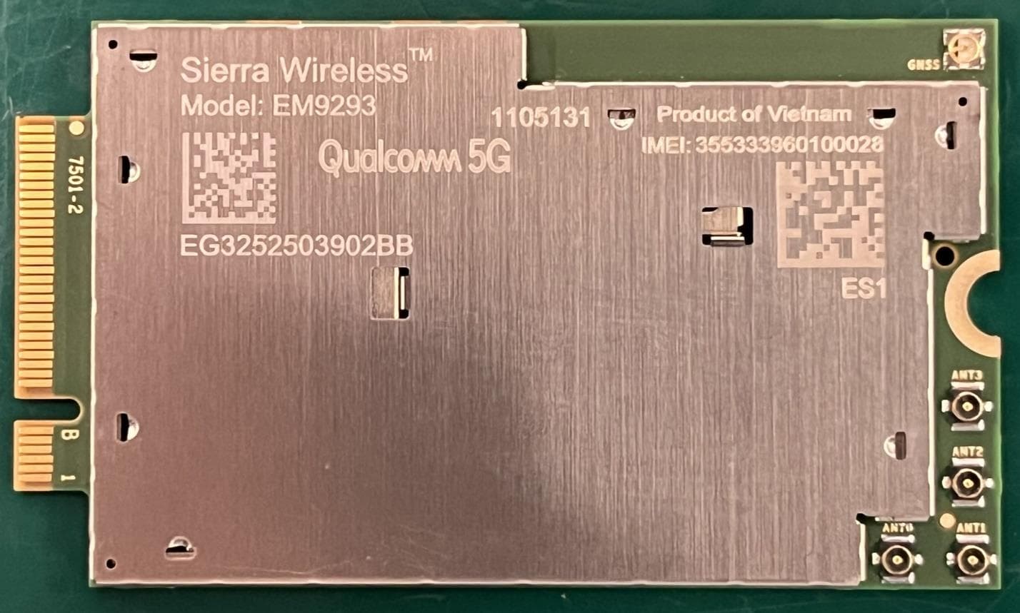
N7NEM92P
Sep 04, 2025Radio Module
Equipment Class
CBE - Citizens Band End User DevicesN7NHL79
Aug 15, 2024Module
Equipment Class
PCB - PCS Licensed Transmitter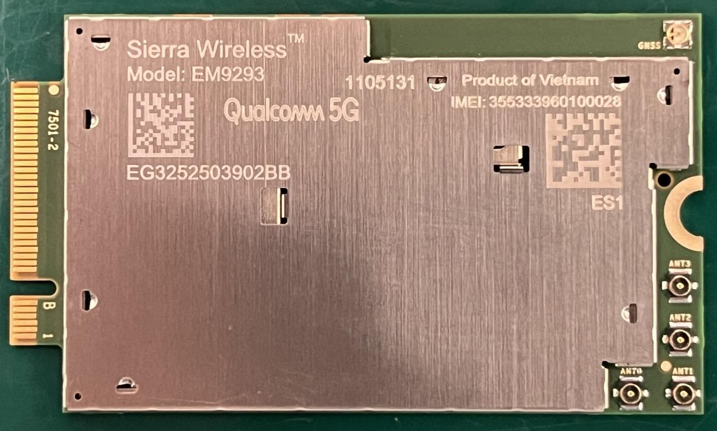
N7NEM92
Sep 26, 2023Radio Module
Equipment Class
CBE - Citizens Band End User Devices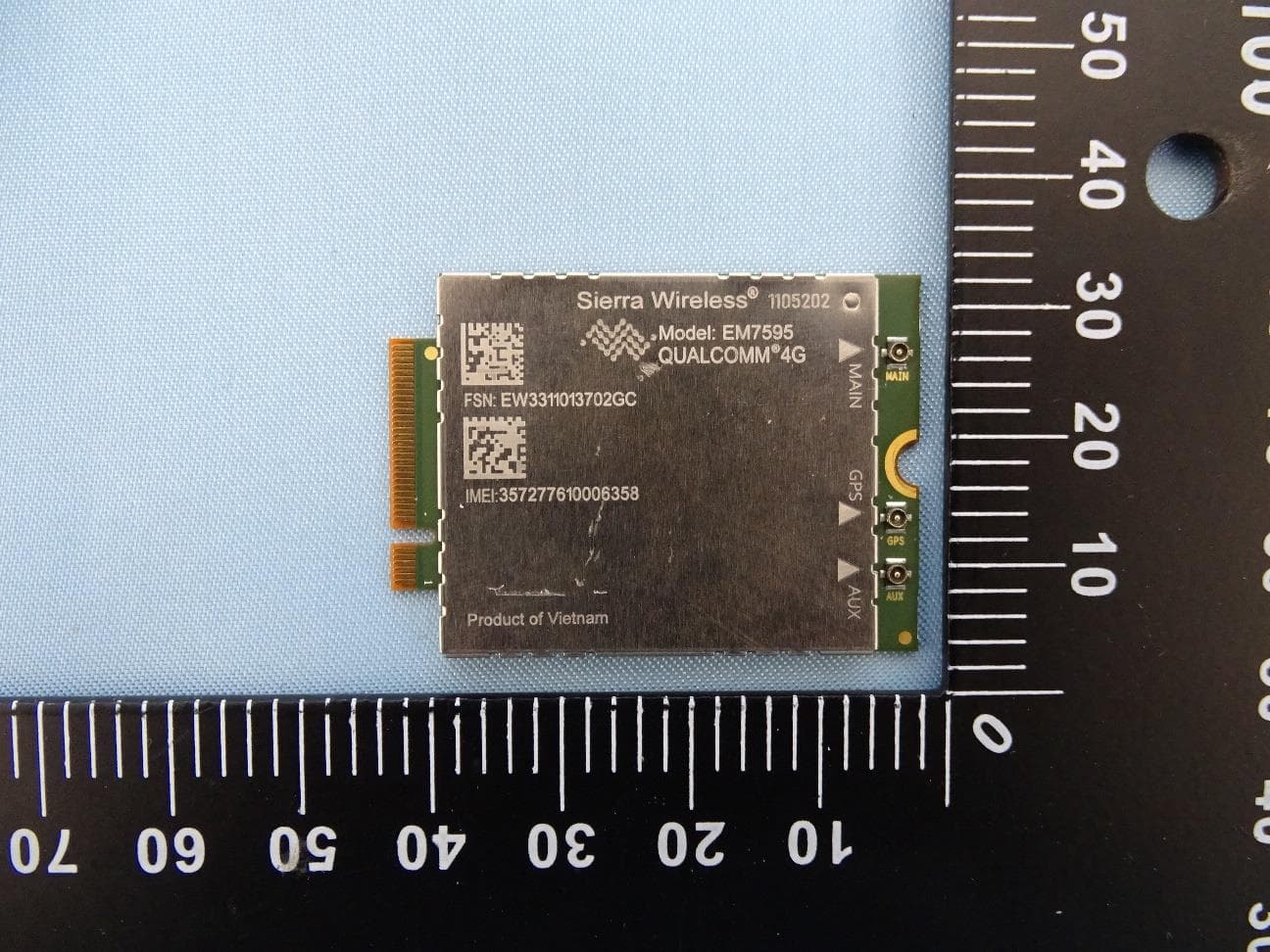
N7NEM75Y
Sep 10, 2023Radio Module
Equipment Class
PCB - PCS Licensed Transmitter