N7NAC850Multi-Mode & Multi-Band Wireless Network Card
Sierra Wireless, ULC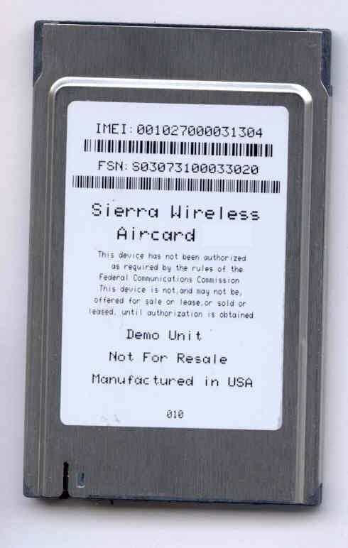
Click to zoom
Application Details
- Equipment Class
- PCB - PCS Licensed Transmitter
- Date of Grant
- Oct 18, 2005
- Application Purpose
- Original Equipment
- Date of Application
- Oct 18, 2005
- Equipment Note
- Multi-Mode & Multi-Band Wireless Network Card
- Frequency Range
- 824.20000000 - 848.80000000
- Company
- Sierra Wireless, ULC
- Country
- Canada
Documents & Files
Document Text
Text extracted from the exhibit documents filed with the FCC. Open a document above to read the original.
Users Manual
2130623 Rev 3.1A AirCard ® 800 Series Wireless Network Cards arInstallation Guide Preface Rev 3.1A Sep.051 Limitation of Liability The information in this manual is subject to change without notice and does not represent a commitment on the part of Sierra Wireless or its affiliates. SIERRA WIRELESS AND ITS AFFILIATES SPECIFICALLY DISCLAIM LIABILITY FOR ANY AND ALL DIRECT, INDIRECT, SPECIAL, GENERAL, INCIDENTAL, CONSEQUENTIAL, PUNITIVE OR EXEMPLARY DAMAGES INCLUDING, BUT NOT LIMITED TO, LOSS OF PROFITS OR REVENUE OR ANTICIPATED PROFITS OR REVENUE ARISING OUT OF THE USE OR INABILITY TO USE ANY SIERRA WIRELESS PRODUCT, EVEN IF SIERRA WIRELESS AND/OR ITS AFFILIATES HAVE BEEN ADVISED OF THE POSSIBILITY OF SUCH DAMAGES OR THEY ARE FORESEEABLE OR FOR CLAIMS BY ANY THIRD PARTY. NOTWITHSTANDING THE FOREGOING, IN NO EVENT SHALL SIERRA WIRELESS AND/OR ITS AFFILIATES’ AGGREGATE LIABILITY ARISING UNDER OR IN CONNECTION WITH THE SIERRA WIRELESS PRODUCT, REGARDLESS OF THE NUMBER OF EVENTS, OCCURRENCES OR CLAIMS GIVING RISE TO LIABILITY, BE IN EXCESS OF THE PRICE PAID BY THE PURCHASER FOR THE SIERRA WIRELESS PRODUCT. PatentsPortions of this product may be covered by some or all of the following US patents: 5,515,0135,629,9605,682,6025,845,2165,847,553 5,878,2345,890,0575,929,8156,169,8846,191,741 6,199,1686,339,4056,359,5916,400,3366,643,501 6,516,2046,561,8516,653,9796,697,0306,785,830 6,845,2496,847,8306,876,6976,879,585D442,170 D459,303 and other patents pending. This product includes technology licensed from: Licensed by QUALCOMM Incorporated under one or more of the following United States patents and/or their counterparts in other nations: 4,901,3075,056,1095,101,5015,109,3905,228,054 5,267,2615,267,2625,337,3385,414,7965,416,797 5,490,1655,504,7735,506,8655,511,0735,535,239 5,544,1965,568,4835,600,7545,657,4205,659,569 5,710,7845,778,338 Manufactured or sold by Sierra Wireless or its licensees under one or more patents licensed from InterDigital Group. Copyright©2005 Sierra Wireless. All rights reserved. AirCard 800 Series Installation Guide 22130623 TrademarksAirCard ® and Heart of the Wireless Machine ® are registered trademarks of Sierra Wireless. Sierra Wireless, the Sierra Wireless logo, the red wave design, the red-tipped antenna, and Watcher are trademarks of Sierra Wireless. Other trademarks are the property of the respective owners. All product specifications are subject to change without notice. Rev 3.1A Sep.053 Table of Contents Introducing the AirCard 800 Series Wireless Network Cards . . .5 AirCard 800 Series wireless network cards . . . . . . . . . . . . . . . . . . . . . . . . . . . . . 5 Supported operating systems . . . . . . . . . . . . . . . . . . . . . . . . . . . . . . . . . . . . 5 The AirCard as a network card . . . . . . . . . . . . . . . . . . . . . . . . . . . . . . . . . . . . 5 HSDPA, UMTS, EDGE, and GPRS service support . . . . . . . . . . . . . . . . . . . 6 Frequency band support . . . . . . . . . . . . . . . . . . . . . . . . . . . . . . . . . . . . . . . . . 6 Your account and coverage area . . . . . . . . . . . . . . . . . . . . . . . . . . . . . . . . . . . . . 7 AirCard software . . . . . . . . . . . . . . . . . . . . . . . . . . . . . . . . . . . . . . . . . . . . . . . . . . . 8 Before you can begin using the AirCard . . . . . . . . . . . . . . . . . . . . . . . . . . . . . . . 8 Package contents . . . . . . . . . . . . . . . . . . . . . . . . . . . . . . . . . . . . . . . . . . . . . . . . . . 8 The SIM Card and Your Account . . . . . . . . . . . . . . . . . . . . . . . . . . . .9 Inserting a SIM card into your AirCard . . . . . . . . . . . . . . . . . . . . . . . . . . . . . . . . 9 Removing a SIM card . . . . . . . . . . . . . . . . . . . . . . . . . . . . . . . . . . . . . . . . . . . . . . 10 Attaching the antenna to your AirCard . . . . . . . . . . . . . . . . . . . . . . . . . . . . . . . 11 Software and Driver Installation . . . . . . . . . . . . . . . . . . . . . . . . . . . .13 System requirements . . . . . . . . . . . . . . . . . . . . . . . . . . . . . . . . . . . . . . . . . . . . . . 13 Installation on Windows 98, 2000, Me, and XP . . . . . . . . . . . . . . . . . . . . . . . . . 13 Setting Internet Explorer to use the AirCard. . . . . . . . . . . . . . . . . . . . . . . . . . . 15 Configuring Your Account . . . . . . . . . . . . . . . . . . . . . . . . . . . . . . . . .17 Setting up a profile . . . . . . . . . . . . . . . . . . . . . . . . . . . . . . . . . . . . . . . . . . . . . . . . 18 Care and Maintenance of Your Network Card . . . . . . . . . . . . . . . .21 Stopping and ejecting the AirCard . . . . . . . . . . . . . . . . . . . . . . . . . . . . . . . . . . . 22 AirCard 800 Series Installation Guide 42130623 Watcher™ Basics . . . . . . . . . . . . . . . . . . . . . . . . . . . . . . . . . . . . . . . . . 23 Launching Watcher. . . . . . . . . . . . . . . . . . . . . . . . . . . . . . . . . . . . . . . . . . . . . . . . 23 The Watcher window . . . . . . . . . . . . . . . . . . . . . . . . . . . . . . . . . . . . . . . . . . . . . . 24 Icons and indicators on the main Watcher window . . . . . . . . . . . . . . . . . . . . 24 View options . . . . . . . . . . . . . . . . . . . . . . . . . . . . . . . . . . . . . . . . . . . . . . . . . . . . . 26 Status icons . . . . . . . . . . . . . . . . . . . . . . . . . . . . . . . . . . . . . . . . . . . . . . . . . . . . . 27 Power Down and Up . . . . . . . . . . . . . . . . . . . . . . . . . . . . . . . . . . . . . . . . . . . 27 Frequency band and network selection. . . . . . . . . . . . . . . . . . . . . . . . . . . . . . . 27 Frequency band selection . . . . . . . . . . . . . . . . . . . . . . . . . . . . . . . . . . . . . . . 28 Network selection . . . . . . . . . . . . . . . . . . . . . . . . . . . . . . . . . . . . . . . . . . . . . 28 Technical Specifications . . . . . . . . . . . . . . . . . . . . . . . . . . . . . . . . . . 29 LED operation . . . . . . . . . . . . . . . . . . . . . . . . . . …
Text truncated - open the document above for the full version.
Cover Letter(s)
September 22, 2005 Federal Communications Commission Authorization and Standards Division 7435 Oakland Mills Road Columbia, M.D. 21046 To Whom It May Concern: Re: Confidentiality Request for FCC ID: N7NAC850 We hereby request that the documentation listed below, submitted with our application for certification, be withheld from public disclosure. This request is made under the provisions of Section 0.457(d) of the Commission’s Rules, and Section 552(b)(4) of the Freedom of Information Act. We cite trade secrets as the reason and purpose of the request. 1. AC850 Schematics 2. AC850 Block Diagram 3. AC850 Theory of Operation 4. AC850 Tune Up Procedure Sincerely, Ying Wang Senior RF Engineer
Cover Letter(s)
1 Mike Kuo From: Claire Hoque Sent: Tuesday, October 04, 2005 2:25 PM To: Mike Kuo Cc: Thu Chan; Christine Vu; William Lau Subject: answer: Sierra Wireless Inc., FCC ID: N7NAC850, Assessment NO.: AN05T5171, Notice#1 ( revised ) Importance: High Hi Mike, Pls see answers below, all the attachments are saved in Z:\TCBUpload\AN05T5171\revised documents Question #1: Based upon the theory of operation, Aircard 850 is capable of operating in the following modulation and frequency bands : GSM850 : 824.2 - 848.8 MHz ( US operation ) EGSM900 :880.2 - 914.8 MHz ( Non-US operation ) DCS 1800: 1710.2- 1784.8 MHz ( Non-US operation ) PCS 1900 : 1850.2 -1909.8 MHz ( US operation ) UMTS2100 : 1920 - 1980 MHz ( Non-US operation ) Please confirm above statement. <answer>The statement is correct. To be more correct, change the UMTS frequency range to UMTS2100 : 1922.4 - 1977.6 MHz (Non-US operation ) because the EUT doesn't transmit right on the band edge. Question #2: Please provide antenna specification for the one used during SAR evaluation. <answer>Pls see the attached document "Attachment to AC850 Operation_Description". Question #3: In Part 22/24 RF conducted test report, the low channel and high channel selected in PCS 1900 band during tests do not agree with the frequency range listed in the TCB application form. The PCS 1900 frequency band listed in the TCB application form:1850.2-1909.8 MHz RF conducted test report low channel= 1850.4 MHz; High channel=1909.6 MHz Please explain. <answer>The revised test report is attached. Question #4: Please provide an exhibit which specifies the DC Voltages and Currents in accordance with FCC 2.1033(c). <answer>Pls see the attached document "Attachment to AC850 Operation_Description". Question #5 : Radiated Part 22/24 report: please provide instrument setting used during radiated spurious emission tests ( RBW / VBW ). <answer>RBW = VBW = 1MHz for radiated spurious emissions with substitution method. Thanks, Claire
ID Label/Location Info
PROPOSED FCC ID LABEL AND LOCATION SIERRA WIRELESS This device complies with Part 22/24 of the FCC Rules. FCC ID: N7NAC850 FCC ID LABEL LOCATION
RF Exposure Info
MAXIMUM PERMISSIBLE EXPOSURE (AirCard 850) LIMITS §1.1310 The criteria listed in Table 1 shall be used to evaluate the environmental impact of human exposure to radio-frequency (RF) radiation as specified in §1.1307(b), except in the case of portable devices which shall be evaluated according to the provisions of §2.1093 of this chapter. CALCULATIONS Given E = √ (30 * P * G) / d and S = E ^ 2 / 3770 where E = Field Strength in Volts/meter P = Power in Watts G = Numeric antenna gain d = Distance in meters S = Power Density in milliwatts/square centimeter Combining equations and rearranging the terms to express the distance as a function of the remaining variables yields: d = √ ((30 * P * G) / (3770 * S)) Changing to units of Power to mW and Distance to cm, using: P (mW) = P (W) / 1000 and d (cm) =100 * d (m) yields d = 100 * √ ((30 * (P / 1000) * G) / (3770 * S)) d = 0.282 * √ (P * G / S) where d = distance in cm P = Power in mW G = Numeric antenna gain S = Power Density in mW/cm^2 Substituting the logarithmic form of power and gain using: P (mW) = 10 ^ (P (dBm) / 10) and G (numeric) = 10 ^ (G (dBi) / 10) yields d = 0.282 * 10 ^ ((P + G) / 20) / √ S where d = MPE distance in cm P = Power in dBm G = Antenna Gain in dBi S = Power Density Limit in mW/cm^2 Rearranging terms to calculate the power density at a specific distance yields S = 0.0795 * 10 ^ ((P + G) / 10) / (d^2) LIMITS From §1.1310 Table 1 (B), the maximum value of S = 1.0 mW/cm^2 RESULTS No non-compliance noted: NOTE: For mobile or fixed location transmitters, the minimum separation distance is 20 cm, even if calculations indicate that the MPE distance would be less. ModeMPEOutputDutyAntennaPower DistancePowerCycleGainDensity (cm)(dBm)(%)(dBi)(mW/cm^2) 800MHz Celllar20.032.000.258.000.50 ModeMPEOutputAntennaPower DistancePowerGainDensity (cm)(dBm)(dBi)(mW/cm^2) 1900 MHz PCS20.029.004.000.24
RF Exposure Info
IN ACCORDANCE WITH THE REQUIREMENTS OF FCC REPORT AND ORDER: ET DOCKET 93-62 AND OET BULLETIN 65 SUPPLEMENT C And RSS-102 Issue 1 (Provisional) September 25, 1999 FOR 850/900/1800/1900/2100 MHz 5-Band PC Card Model: AirCard 850 FCC ID: N7NAC850 REPORT NUMBER: 05U3649-6 ISSUE DATE: September 16, 2005 Prepared for Sierra Wireless, Inc. 13811 Wireless Way Richmond, British Columbia V6V 3A4 Canada Prepared by COMPLIANCE CERTIFICATION SERVICES 561F MONTEREY ROAD, MORGAN HILL, CA 95037 United States REPORT NO: 05U3649-6 DATE: September 16, 2005 FCC ID: N7NAC850 COMPLIANCE CERTIFICATION SERVICES Page 2 of 36 This report shall not be reproduced except in full, without the written approval of CCS. Revision History Rev. Issued date Revisions Revised By A September 16, 2005 Initial Issue HS REPORT NO: 05U3649-6 DATE: September 16, 2005 FCC ID: N7NAC850 COMPLIANCE CERTIFICATION SERVICES Page 3 of 36 This report shall not be reproduced except in full, without the written approval of CCS. CERTIFICATE OF COMPLIANCE (SAR EVALUATION) DATES OF TEST: September 15 - 16, 2005 APPLICANT: ADDRESS: Sierra Wireless, Inc. 13811 Wireless Way Richmond, British Columbia V6V 3A4, Canada FCC ID: MODEL: N7NAC850 AirCard 850 DEVICE CATEGORY: EXPOSURE CATEGORY: Portable Device General Population/Uncontrolled Exposure 850/900/1800/1900/2100 MHz 5-Band PC Card Note: This device contains 900/1800/2100 MHz bands are not operational in US territories. This report is applicable to 850 and 1900 MHz bands. Test Sample is a: Identical prototype unit Host devices: Host # 1: Toshiba, Satellite Host # 2: NEC, VERSA SX Host # 3: Compaq, ARMADA E500 FCC Rule Parts Frequency Range [MHz] The Highest SAR Values (1g) 22H (GSM) 824.2 – 848.8 body: 0.378 mW/g 24E (GSM) 1850.2 – 1909.8 body: 0.460 mW/g This wireless portable device has been shown to be capable of compliance for localized specific absorption rate (SAR) for General Population/Uncontrolled Exposure limits specified in ANSI/IEEE Std. C95.1-1992 and had been tested in accordance with the measurement procedures specified in FCC OET 65 Supplement C (Edition 01-01). And RSS-102 Issue 1 (Provisional) September 25, 1999. The maximum 1g SAR level measured for all the tests performed did not exceed the limits for General Population/Uncontrolled Exposure (W/kg) Partial Body of 1.6 W/kg. Level defined in Supplement C (Edition 01-01) to OET Bulletin 65 (97-01). Note: The results documented in this report apply only to the tested sample, under the conditions and modes of operation as described herein. This document may not be altered or revised in any way unless done so by Compliance Certification Services and all revisions are duly noted in the revisions section. Any alteration of this document not carried out by Compliance Certification Services will constitute fraud and shall nullify the document. No part of this report may be used to claim product certification, approval, or endorsement by NVLAP, NIST, or any government agency. Released For CCS By: Hsin Fu Shih SENIOR ENGINEER COMPLIANCE CERTIFICATION SERVICES REPORT NO: 05U3649-6 DATE: September 16, 2005 FCC ID: N7NAC850 COMPLIANCE CERTIFICATION SERVICES Page 4 of 36 This report shall not be reproduced except in full, without the written approval of CCS. Table of Contents 1 Equipment Under Test (EUT) Description........................................................................................... 5 2 FACILITIES AND ACCREDITATION .................................................................................................. 6 3 System Description ............................................................................................................................. 7 4 System Component............................................................................................................................. 8 4.1 DASY4 Measurement Server...................................................................................................... 8 4.2 Data Acquisition Electronics (DAE).............................................................................................8 4.3 EX3DV3 Isotropic E-Field Probe for Dosimetric Measurements................................................. 8 4.4 Light Beam Unit .......................................................................................................................... 9 4.5 SAM Phantom (V4.0) .................................................................................................................. 9 4.6 Device Holder for SAM Twin Phantom ..................................................................................... 10 4.7 System Validation Kits .............................................................................................................. 10 4.8 Composition of Ingredients for tissue simulating liquid ............................................................. 10 5 Test positions for devices Operating Next To A Person’s Ear .......................................................... 11 5.1 Cheek/Touch Position............................................................................................................... 12 5.2 Ear/Tilt Position......................................................................................................................... 13 6 Test Positions For Body-worn And Other Similar Configurations...................................................... 14 7 Simulating Liquid Parameters Check ................................................................................................ 15 7.1 Simulating Liquid Parameter Check Result .............................................................................. 16 8 System Performance Check ............................................................................................................. 18 8.1 System Performance Check Results ........................................................................................ 19 9 SAR Measurement Procedure .....…
Text truncated - open the document above for the full version.
RF Exposure Info
Date/Time: 9/15/2005 12:41:06 PM Test Laboratory: Compliance Certification Services System Performance Check @ 1900MHz DUT: Dipole 1900 MHz; Type: D1900V2; Serial: D1900V2 - SN: 5d043 Communication System: CW; Frequency: 1900 MHz;Duty Cycle: 1:1 Medium parameters used: f = 1900 MHz; σ = 1.57 mho/m; ε r = 51.4; ρ = 1000 kg/m 3 Phantom section: Flat Section Room Ambient Temperature: 23.0 deg. C; Liquid Temperature: 22.0 deg. C DASY4 Configuration: - Area Scan setting - Find Secondary Maximum Within: 2.0 dB and with a peak SAR value greater than 0.0012W/kg - Probe: EX3DV3 - SN3531; ConvF(8.33, 8.33, 8.33); Calibrated: 7/21/2005 - Sensor-Surface: 4mm (Mechanical Surface Detection) - Electronics: DAE3 Sn500; Calibrated: 2/7/2005 - Phantom: SAM 2; Type: SAM 2; Serial: 1050 - Measurement SW: DASY4, V4.6 Build 19; Postprocessing SW: SEMCAD, V1.8 Build 159 d=10mm, Pin=250mW/Area Scan (7x7x1): Measurement grid: dx=15mm, dy=15mm Maximum value of SAR (measured) = 8.68 mW/g d=10mm, Pin=250mW/Zoom Scan (5x5x7)/Cube 0: Measurement grid: dx=7.5mm, dy=7.5mm, dz=5mm Reference Value = 83.6 V/m; Power Drift = -0.051 dB Peak SAR (extrapolated) = 16.0 W/kg SAR(1 g) = 9.22 mW/g; SAR(10 g) = 4.79 mW/g Maximum value of SAR (measured) = 10.3 mW/g 0 dB = 10.3mW/g Date/Time: 9/15/2005 12:52:04 PM Test Laboratory: Compliance Certification Services System Performance Check @ 1900MHz DUT: Dipole 1900 MHz; Type: D1900V2; Serial: D1900V2 - SN: 5d043 Communication System: CW; Frequency: 1900 MHz;Duty Cycle: 1:1 d=10mm, Pin=250mW/Z Scan (1x1x21): Measurement grid: dx=20mm, dy=20mm, dz=5mm Maximum value of SAR (measured) = 5.91 mW/g Date/Time: 9/16/2005 4:08:06 PM Test Laboratory: Compliance Certification Services System Performance Check @ 835MHz DUT: Dipole 835 MHz; Type: D835V2; Serial: D835V2 - SN:4d002 Communication System: CW; Frequency: 835 MHz;Duty Cycle: 1:1 Medium parameters used: f = 835 MHz; σ = 0.952 mho/m; ε r = 53; ρ = 1000 kg/m 3 Phantom section: Flat Section Room Ambient Temperature: 23.0 deg. C; Liquid Temperature: 22.0 deg. C DASY4 Configuration: - Area Scan setting - Find Secondary Maximum Within: 2.0 dB and with a peak SAR value greater than 0.0012W/kg - Probe: EX3DV3 - SN3531; ConvF(10.54, 10.54, 10.54); Calibrated: 7/21/2005 - Sensor-Surface: 4mm (Mechanical Surface Detection) - Electronics: DAE3 Sn500; Calibrated: 2/7/2005 - Phantom: SAM 2; Type: SAM 2; Serial: 1050 - Measurement SW: DASY4, V4.6 Build 19; Postprocessing SW: SEMCAD, V1.8 Build 159 d=15mm, Pin=250mW/Area Scan (7x9x1): Measurement grid: dx=15mm, dy=15mm Maximum value of SAR (measured) = 2.47 mW/g d=15mm, Pin=250mW/Zoom Scan (5x5x7)/Cube 0: Measurement grid: dx=7.5mm, dy=7.5mm, dz=5mm Reference Value = 51.7 V/m; Power Drift = -0.153 dB Peak SAR (extrapolated) = 3.39 W/kg SAR(1 g) = 2.3 mW/g; SAR(10 g) = 1.51 mW/g Maximum value of SAR (measured) = 2.48 mW/g 0 dB = 2.48mW/g Date/Time: 9/16/2005 4:19:47 PM Test Laboratory: Compliance Certification Services System Performance Check @ 835MHz DUT: Dipole 835 MHz; Type: D835V2; Serial: D835V2 - SN:4d002 Communication System: CW; Frequency: 835 MHz;Duty Cycle: 1:1 d=15mm, Pin=250mW/Z Scan (1x1x41): Measurement grid: dx=20mm, dy=20mm, dz=2.5mm Maximum value of SAR (measured) = 2.49 mW/g
RF Exposure Info
Date/Time: 9/16/2005 4:43:38 PM Test Laboratory: Compliance Certification Services 1_Host # 1_Toshiba Satellite DUT: Sierra Wireless; Type: AirCard 850; Serial: X1620350034E2 Communication System: GSM850; Frequency: 837 MHz;Duty Cycle: 1:4 Medium parameters used (interpolated): f = 837 MHz; σ = 0.954 mho/m; ε r = 53; ρ = 1000 kg/m 3 Phantom section: Flat Section Room Ambient Temperature: 23.0 deg. C; Liquid Temperature: 22.0 deg. C DASY4 Configuration: - Area Scan setting - Find Secondary Maximum Within: 2.0 dB and with a peak SAR value greater than 0.0012W/kg - Probe: EX3DV3 - SN3531; ConvF(10.54, 10.54, 10.54); Calibrated: 7/21/2005 - Sensor-Surface: 4mm (Mechanical Surface Detection) - Electronics: DAE3 Sn500; Calibrated: 2/7/2005 - Phantom: SAM 2; Type: SAM 2; Serial: 1050 - Measurement SW: DASY4, V4.6 Build 19; Postprocessing SW: SEMCAD, V1.8 Build 159 GSM835 2Slot_M-ch/Area Scan (9x7x1): Measurement grid: dx=15mm, dy=15mm Info: Interpolated medium parameters used for SAR evaluation. Maximum value of SAR (measured) = 0.214 mW/g GSM835 2Slot_M-ch/Zoom Scan (5x5x7)/Cube 0: Measurement grid: dx=7.5mm, dy=7.5mm, dz=5mm Reference Value = 13.9 V/m; Power Drift = -0.175 dB Peak SAR (extrapolated) = 0.317 W/kg SAR(1 g) = 0.205 mW/g; SAR(10 g) = 0.136 mW/g Info: Interpolated medium parameters used for SAR evaluation. Maximum value of SAR (measured) = 0.221 mW/g Date/Time: 9/16/2005 4:55:37 PM Test Laboratory: Compliance Certification Services 1_Host # 1_Toshiba Satellite DUT: Sierra Wireless; Type: AirCard 850; Serial: X1620350034E2 Communication System: GSM850; Frequency: 837 MHz;Duty Cycle: 1:4 GSM835 2Slot_M-ch/Z Scan (1x1x41): Measurement grid: dx=20mm, dy=20mm, dz=2.5mm Info: Interpolated medium parameters used for SAR evaluation. Maximum value of SAR (measured) = 0.275 mW/g Date/Time: 9/16/2005 5:00:21 PM Test Laboratory: Compliance Certification Services 1_Host # 1_Toshiba Satellite DUT: Sierra Wireless; Type: AirCard 850; Serial: X1620350034E2 Communication System: GSM850; Frequency: 837 MHz;Duty Cycle: 1:4 Medium parameters used (interpolated): f = 837 MHz; σ = 0.954 mho/m; ε r = 53; ρ = 1000 kg/m 3 Phantom section: Flat Section Room Ambient Temperature: 23.0 deg. C; Liquid Temperature: 22.0 deg. C DASY4 Configuration: - Area Scan setting - Find Secondary Maximum Within: 2.0 dB and with a peak SAR value greater than 0.0012W/kg - Probe: EX3DV3 - SN3531; ConvF(10.54, 10.54, 10.54); Calibrated: 7/21/2005 - Sensor-Surface: 4mm (Mechanical Surface Detection) - Electronics: DAE3 Sn500; Calibrated: 2/7/2005 - Phantom: SAM 2; Type: SAM 2; Serial: 1050 - Measurement SW: DASY4, V4.6 Build 19; Postprocessing SW: SEMCAD, V1.8 Build 159 EDGE835 2Slot_M-ch/Area Scan (9x7x1): Measurement grid: dx=15mm, dy=15mm Info: Interpolated medium parameters used for SAR evaluation. Maximum value of SAR (measured) = 0.069 mW/g EDGE835 2Slot_M-ch/Zoom Scan (5x5x7)/Cube 0: Measurement grid: dx=7.5mm, dy=7.5mm, dz=5mm Reference Value = 7.95 V/m; Power Drift = -0.067 dB Peak SAR (extrapolated) = 0.104 W/kg SAR(1 g) = 0.069 mW/g; SAR(10 g) = 0.046 mW/g Info: Interpolated medium parameters used for SAR evaluation. Maximum value of SAR (measured) = 0.074 mW/g Date/Time: 9/16/2005 6:25:57 PM Test Laboratory: Compliance Certification Services 2_Host # 2_NEC VERSA SX DUT: Sierra Wireless; Type: AirCard 850; Serial: X1620350034E2 Communication System: GSM850; Frequency: 824.2 MHz;Duty Cycle: 1:4 Medium parameters used: f = 825 MHz; σ = 0.943 mho/m; ε r = 53.1; ρ = 1000 kg/m 3 Phantom section: Flat Section Room Ambient Temperature: 23.0 deg. C; Liquid Temperature: 22.0 deg. C DASY4 Configuration: - Area Scan setting - Find Secondary Maximum Within: 2.0 dB and with a peak SAR value greater than 0.0012W/kg - Probe: EX3DV3 - SN3531; ConvF(10.54, 10.54, 10.54); Calibrated: 7/21/2005 - Sensor-Surface: 4mm (Mechanical Surface Detection) - Electronics: DAE3 Sn500; Calibrated: 2/7/2005 - Phantom: SAM 2; Type: SAM 2; Serial: 1050 - Measurement SW: DASY4, V4.6 Build 19; Postprocessing SW: SEMCAD, V1.8 Build 159 GSM835 2Slot_L-ch/Area Scan (9x7x1): Measurement grid: dx=15mm, dy=15mm Maximum value of SAR (measured) = 0.304 mW/g GSM835 2Slot_L-ch/Zoom Scan (5x5x7)/Cube 0: Measurement grid: dx=7.5mm, dy=7.5mm, dz=5mm Reference Value = 18.1 V/m; Power Drift = -0.037 dB Peak SAR (extrapolated) = 0.442 W/kg SAR(1 g) = 0.296 mW/g; SAR(10 g) = 0.196 mW/g Maximum value of SAR (measured) = 0.315 mW/g Date/Time: 9/16/2005 6:08:32 PM Test Laboratory: Compliance Certification Services 2_Host # 2_NEC VERSA SX DUT: Sierra Wireless; Type: AirCard 850; Serial: X1620350034E2 Communication System: GSM850; Frequency: 837 MHz;Duty Cycle: 1:4 Medium parameters used (interpolated): f = 837 MHz; σ = 0.954 mho/m; ε r = 53; ρ = 1000 kg/m 3 Phantom section: Flat Section Room Ambient Temperature: 23.0 deg. C; Liquid Temperature: 22.0 deg. C DASY4 Configuration: - Area Scan setting - Find Secondary Maximum Within: 2.0 dB and with a peak SAR value greater than 0.0012W/kg - Probe: EX3DV3 - SN3531; ConvF(10.54, 10.54, 10.54); Calibrated: 7/21/2005 - Sensor-Surface: 4mm (Mechanical Surface Detection) - Electronics: DAE3 Sn500; Calibrated: 2/7/2005 - Phantom: SAM 2; Type: SAM 2; Serial: 1050 - Measurement SW: DASY4, V4.6 Build 19; Postprocessing SW: SEMCAD, V1.8 Build 159 GSM835 2Slot_M-ch/Area Scan (9x7x1): Measurement grid: dx=15mm, dy=15mm Info: Interpolated medium parameters used for SAR evaluation. Maximum value of SAR (measured) = 0.355 mW/g GSM835 2Slot_M-ch/Zoom Scan (5x5x7)/Cube 0: Measurement grid: dx=7.5mm, dy=7.5mm, dz=5mm Reference Value = 19.3 V/m; Power Drift = -0.066 dB Peak SAR (extrapolated) = 0.503 W/kg SAR(1 g) = 0.332 mW/g; SAR(10 g) = 0.219 mW/g Info: Interpolated medium parameters used for SAR evaluation. Maximum value of SAR (measured) = 0.357 mW/g Date/Time: 9/16/2005 6:43:17 PM Test Laboratory: Compliance Certification Services 2_Host # 2_NEC VERSA SX DUT: Sierra Wireless; Type: AirCard 850; Serial: X1620350034E2 Communication System: GSM8…
Text truncated - open the document above for the full version.
Test Report
2004 Sierra Wireless, Inc. This document contains information which is proprietary and confidential to Sierra Wireless, Inc. Disclosure to persons other than the officers, employees, agents, or subcontractors of the Company or licensee of this document without the prior written permission of Sierra Wireless, Inc. is strictly prohibited. AirCard 850 Test Report For FCC Certification FCC ID: N7NAC850 Prepared by SIERRA WIRELESS INC. 13811 WIRELESS WAY RICHMOND, BC V6V 3A4 CANADA Test Date(s): September 12, 2005, October 3, 2005 SIERRA WIRELESS, INC. FCC Part 22 & 24 Test Report AC850 Sept 12, 2005 Page 2 of 50 2005 Sierra Wireless, Inc. The contents of this page are subject to the confidentiality information on page one. Table of Contents 1 Introduction and Purpose ......................................................................... 3 2 Test Summary .......................................................................................... 3 3 Description of Equipment Under Test ..................................................... 4 4 RF Power Output ..................................................................................... 5 4.1 Test Procedure .................................................................................................... 5 4.2 Test Equipment.................................................................................................... 5 4.3 Test Results ......................................................................................................... 6 5 Occupied Bandwidth................................................................................ 7 5.1 Test Procedure .................................................................................................... 7 5.2 Test Results ......................................................................................................... 7 5.3 Test Plots............................................................................................................. 8 6 Out of Band Emissions at Antenna Terminals ...................................... 14 6.1 Test Procedure .................................................................................................. 14 6.2 Test Equipment.................................................................................................. 14 6.3 Test Results ....................................................................................................... 15 6.4 Test Plots........................................................................................................... 16 7 Block Edge Compliance ........................................................................ 40 7.1 Test Procedure .................................................................................................. 40 7.2 Test Equipment.................................................................................................. 40 7.3 Instrument List .................................................................................................. 40 7.4 Test Results ....................................................................................................... 40 7.5 Test Plots........................................................................................................... 41 8 Frequency Stability Versus Temperature .............................................. 45 8.1 Summary of Results........................................................................................... 45 8.2 Test Procedure .................................................................................................. 45 8.3 Test Equipment.................................................................................................. 45 8.4 Test Results ....................................................................................................... 46 9 Frequency Stability Versus Voltage ...................................................... 48 9.1 Summary of Results...................................................................................…
Text truncated - open the document above for the full version.
Contact Information
Applicant
Ying Wang(Director, Regulatory Compliance)
Test Firm
Compliance Certification Services IncSteve Cheng
Technical Specifications
| # | Rule Parts | Frequency Range | Power Output | Emission | Tolerance |
|---|---|---|---|---|---|
| 4 | 22H | 824.2 MHz - 848.8 MHz | 1.48 W | 243KGXW | 2.5 ppm |
Other Applications from Sierra Wireless, ULC
N7NHL79E
Feb 23, 2026Radio Module
Equipment Class
PCB - PCS Licensed Transmitter
N7NEM92P
Sep 04, 2025Radio Module
Equipment Class
CBE - Citizens Band End User DevicesN7NHL79
Aug 15, 2024Module
Equipment Class
PCB - PCS Licensed Transmitter
N7NEM92
Sep 26, 2023Radio Module
Equipment Class
CBE - Citizens Band End User Devices
N7NEM75Y
Sep 10, 2023Radio Module
Equipment Class
PCB - PCS Licensed Transmitter