N7NMC8755850/900/1800/1900/2100 MHz 5-Band MiniCard Module
Sierra Wireless, ULC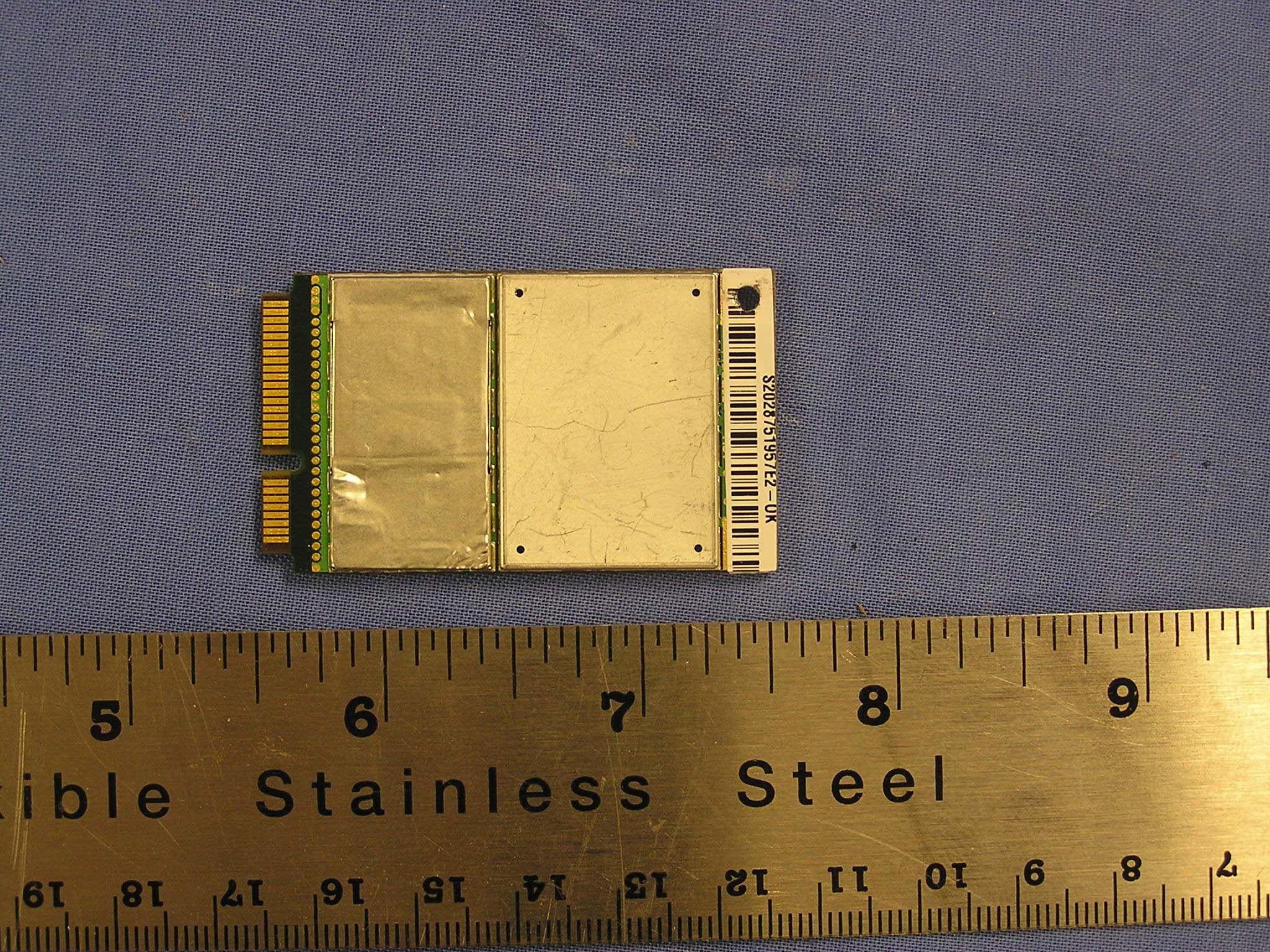
Click to zoom
Application Details
- Equipment Class
- PCB - PCS Licensed Transmitter
- Date of Grant
- Jan 29, 2006
- Application Purpose
- Original Equipment
- Date of Application
- Jan 29, 2006
- Equipment Note
- 850/900/1800/1900/2100 MHz 5-Band MiniCard Module
- Frequency Range
- 824.20000000 - 848.80000000
- Company
- Sierra Wireless, ULC
- Country
- Canada
Documents & Files
Document Text
Text extracted from the exhibit documents filed with the FCC. Open a document above to read the original.
Users Manual
2130114 Rev 0.92 MC5720, MC8755, MC8765 MiniCard Hardware Integration Guide Proprietary and Confidential Limitation of Liability Patents Copyright Preface The information in this manual is subject to change without notice and does not represent a commitment on the part of Sierra Wireless. SIERRA WIRELESS AND ITS AFFILIATES SPECIFICALLY DISCLAIM LIABILITY FOR ANY AND ALL DIRECT, INDIRECT, SPECIAL, GENERAL, INCIDENTAL, CONSEQUENTIAL, PUNITIVE OR EXEMPLARY DAMAGES INCLUDING, BUT NOT LIMITED TO, LOSS OF PROFITS OR REVENUE OR ANTICIPATED PROFITS OR REVENUE ARISING OUT OF THE USE OR INABILITY TO USE ANY SIERRA WIRELESS PRODUCT, EVEN IF SIERRA WIRELESS AND/OR ITS AFFILIATES HAS BEEN ADVISED OF THE POSSIBILITY OF SUCH DAMAGES OR THEY ARE FORESEEABLE OR FOR CLAIMS BY ANY THIRD PARTY. Notwithstanding the foregoing, in no event shall Sierra Wireless and/or its affiliates aggregate liability arising under or in connection with the Sierra Wireless product, regardless of the number of events, occurrences, or claims giving rise to liability, be in excess of the price paid by the purchaser for the Sierra Wireless product. Portions of this product may be covered by some or all of the following US patents: 5,515,013 5,629,960 5,845,216 5,847,553 5,878,234 5,890,057 5,929,815 6,169,884 6,191,741 6,199,168 6,339,405 6,359,591 6,400,336 6,643,501 6,516,204 6,561,851 6,653,979 6,697,030 6,785,830 6,845,249 6,847,830 6,876,697 6,879,585 6,886,049 D442,170 D459,303 and other patents pending. This product includes technology licensed from: Licensed by QUALCOMM Incorporated under one or more of the following United States patents and/or their counterparts in other nations: 4,901,307 5,056,109 5,101,501 5,109,390 5,228,054 5,267,261 5,267,262 5,337,338 5,414,796 5,416,797 5,490,165 5,504,773 5,506,865 5,511,073 5,535,239 5,544,196 5,568,483 5,600,754 5,657,420 5,659,569 5,710,784 5,778,338 Manufactured or sold by Sierra Wireless or its licensees under one or more patents licensed from InterDigital Group. ©2005 Sierra Wireless. All rights reserved. Rev 0.92 Nov.05 1 MC5720/8755/8765 Hardware Integration Guide Trademarks Contact Information AirCard and “Heart of the Wireless Machine” are registered trademarks of Sierra Wireless. Sierra Wireless, the Sierra Wireless logo, the red wave design, the red‐tipped antenna, and Watcher are trademarks of Sierra Wireless. Windows ® is a registered trademark of Microsoft Corporation. Qualcomm ® is a registered trademark of Qualcomm Incorpo‐ rated. Other trademarks are the property of the respective owners. Sales Desk: Phone: 1-604-232-1488 Hours: 8:00 AM to 5:00 PM Pacific Time E-mail: [email protected] Post: Sierra Wireless 13811 Wireless Way Richmond, BC Canada V6V 3A4 Fax: 1-604-231-1109 Web: www.sierrawireless.com Consult our website for up‐to‐date product descriptions, documentation, application notes, firmware upgrades, trouble‐ shooting tips, and press releases: www.sierrawireless.com 2 2130114 Table of Contents Introduction . . . . . . . . . . . . . . . . . . . . . . . . . . . . . . . . . . . . . . . . . . . . . . .5 The Universal Development Kit . . . . . . . . . . . . . . . . . . . . . . . . . . . . . . . . . . . . . . 5 Required connectors . . . . . . . . . . . . . . . . . . . . . . . . . . . . . . . . . . . . . . . . . . . . . . . 5 Guide Organization. . . . . . . . . . . . . . . . . . . . . . . . . . . . . . . . . . . . . . . . . . . . . . . . . 6 Related documents. . . . . . . . . . . . . . . . . . . . . . . . . . . . . . . . . . . . . . . . . . . . . . . . . 6 Power Interface . . . . . . . . . . . . . . . . . . . . . . . . . . . . . . . . . . . . . . . . . . . .9 Overview of operation. . . . . . . . . . . . . . . . . . . . . . . . . . . . . . . . . . . . . . . . . . . . . . . 9 Power signals . . . . . . . . . . . . . . . . . . . . . . . . . . . . . . . . . . . . . . . . . . . . . . . . . . 9 Electrostatic discharge (ESD) . . . . . . . . . . . . . . . . . . . . . . . . . . . . . . . . . . . . 9 Module power states . . . . . . . . . . . . . . . . . . . . . . . . . . . . . . . . . . . . . . . . . . . . . . 10 Disconnected state . . . . . . . . . . . . . . . . . . . . . . . . . . . . . . . . . . . . . . . . . . . . 10 Off state . . . . . . . . . . . . . . . . . . . . . . . . . . . . . . . . . . . . . . . . . . . . . . . . . . . . . . 10 Normal state . . . . . . . . . . . . . . . . . . . . . . . . . . . . . . . . . . . . . . . . . . . . . . . . . . 11 Low power mode . . . . . . . . . . . . . . . . . . . . . . . . . . . . . . . . . . . . . . . . . . . . . . 11 Usage models . . . . . . . . . . . . . . . . . . . . . . . . . . . . . . . . . . . . . . . . . . . . . . . . . 11 RF Integration . . . . . . . . . . . . . . . . . . . . . . . . . . . . . . . . . . . . . . . . . . . .13 RF connection . . . . . . . . . . . . . . . . . . . . . . . . . . . . . . . . . . . . . . . . . . . . . . . . . . . . 13 Ground connection. . . . . . . . . . . . . . . . . . . . . . . . . . . . . . . . . . . . . . . . . . . . . . . . 13 Shielding . . . . . . . . . . . . . . . . . . . . . . . . . . . . . . . . . . . . . . . . . . . . . . . . . . . . . 14 Antenna and cabling . . . . . . . . . . . . . . . . . . . . . . . . . . . . . . . . . . . . . . . . . . . 14 Interference and sensitivity. . . . . . . . . . . . . . . . . . . . . . . . . . . . . . . . . . . . . . . . . 15 Power supply noise . . . . . . . . . . . . . . . . . . . . . . . . . . . . . . . . . . . . . . . . . . . . 15 Interference from other wireless devices . . . . . . . . . . . . . . . . . . . . . . . . . . 15 Device-generated RF . . . . . . . . . . . . . . . . . . . . . . . . . . . . . . . . . . . . . . . . . . . 16 Host/Module Communication Interface . . . . . . . . . . . . . . . . . . . . .17 Rev 0.92 Nov.05 3 MC5720/8755/8765 Hardware Integration Guide LED output . . . . . . . . . . . . . . . . . . . . . . . . . . . . . . . . . . . . . . . . . . . . . . . . . . . 17 Regulatory Information . . . . . . . . . . . . . . . . . . …
Text truncated - open the document above for the full version.
Users Manual
Part Number: 41W3221 ThinkPad T60 Series supplementary regulatory notice Read first — regulatory information Regulatory notice for ThinkPad T60 Series This notice is a supplementary document of the ThinkPad T60 Series Service and Troubleshooting Guide. Please read this document before you use the ThinkPad T60 Series computer. The ThinkPad T60 Series computer complies with the radio frequency and safety standards of any country or region in which it has been approved for wireless use. You must install and use your ThinkPad T60 Series computer in strict accordance with the instructions as described hereafter. Avis de réglementation pour les ThinkPad T60 Series Le présent avis est un document qui vient compléter le ThinkPad T60 Series Guide de maintenance et d’identification des incidents. Veuillez lire ce document avant d’utiliser l’ordinateur ThinkPad T60 Series. L’ordinateur ThinkPad T60 Series est conforme aux normes de sécurité et de radiofréquence du pays ou de la région où son utilisation sans fil est agréée. Vous devez installer et utiliser votre ordinateur ThinkPad T60 Series en respectant scrupuleusement les instructions décrites ci-après. Hinweis für ThinkPad T60 Series Bei diesem Hinweis handelt es sich um ein ergänzendes Dokument für das Handbuch ThinkPad T60 Series Service und Fehlerbehebung. Lesen Sie vor dem Verwenden des ThinkPad T60 Series-Computers dieses Dokument. Der ThinkPad T60 Series erfüllt die Funkfrequenz- und Sicherheitsstandards der Länder oder Regionen, in denen er für die Verwendung als drahtlose Einheit zugelassen ist. Der ThinkPad T60 Series muss entsprechend den Installationsanweisungen und entsprechend den gültigen Richtlinien für drahtlose Einheiten installiert und verwendet werden. © Copyright Lenovo 2006 1 Aviso de regulación para ThinkPad T60 Series Este aviso es un documento adicional del manual ThinkPad T60 Series Guía de servicio y de resolución de problemas. Antes de utilizar el sistema ThinkPad T60 Series, lea este documento. El sistema ThinkPad T60 Series satisface los estándares de seguridad y de frecuencia de radio de cualquier país o región en el que se haya aprobado su utilización para conexiones inalámbricas. El usuario debe instalar y utilizar el sistema ThinkPad T60 Series siguiendo estrictamente las instrucciones que se describen a continuación. Informazioni importanti sul ThinkPad T60 Series Queste informazioni importanti costituiscono un documento integrativo della ThinkPad T60 Series Guida all’assistenza e alla risoluzione dei problemi. Prima di utilizzare l’elaboratore ThinkPad T60 Series, leggere il presente documento. L’elaboratore ThinkPad T60 Series è conforme agli standard di sicurezza e di frequenza radio di ciascun paese in cui è stato approvato per l’utilizzo della tecnologia senza fili. E’, quindi, necessario installare ed utilizzare l’elaboratore ThinkPad T60 Series in stretta osservanza alle istruzioni di seguito riportate. Tietoja ThinkPad T60 Series- tietokoneeseen liittyvistä viranomaismääräyksistä Tämä asiakirja täydentää ThinkPad T60 Series Käyttö ja vianmääritys -julkaisun tietoja. Lue tämä asiakirjan sisältö, ennen kuin aloitat ThinkPad T60 Series -tietokoneen käytön. ThinkPad T60 Series -tietokone on paikallisten radiotaajuus- ja turvallisuusstandardien mukainen niissä maissa ja niillä alueilla, joilla se on hyväksytty langattomaan yhteyskäyttöön. Käyttäjän on ehdottomasti noudatettava jäljempänä annettuja ohjeita ThinkPad T60 Series-tietokoneen asennuksen ja käytön aikana. Kennisgeving inzake de veiligheid van de ThinkPad T60 Series Deze kennisgeving vormt een aanvulling op de ThinkPad T60 Series Gids voor Service en Probleemoplossing. Lees dit document alstublieft voordat u de ThinkPad T60 Series-computer in gebruik neemt. De ThinkPad T60 Series-computer voldoet aan de veiligheidsnormen en de normen voor stralingsafgifte op radiofrequenties voor alle landen en regio’s waarin draadloos gebruik van deze computer is toegestaan. Bij het installeren en gebruiken van de ThinkPad T60 Series-computer dient u de hierna beschreven instructies stipt op te volgen. 2 Bemækning vedr. ThinkPad T60 Series-computeren Denne bemærkning er et supplement til bogen Guide til service og fejlfinding. Læs dette dokument, før du bruger ThinkPad T60 Series-computeren. ThinkPad T60 Series-computeren overholder radiofrekvens- og sikkerhedsstandarderne i de lande og områder, hvor den er godkendt til trådløs brug. Du skal installere og bruge ThinkPad T60 Series-computeren i nøje overensstemmelse med den vejledning, der beskrives her. Merknad om forskrifter for ThinkPad T60 Series Denne merknaden er et tillegg til opplysningene i ThinkPad T60 Series Håndbok for service og problemløsing. Du må lese dette dokumentet før du bruker ThinkPad T60 Series-maskinen. ThinkPad T60 Series-maskinen er i overensstemmelse med standardene for radiofrekvenssignaler og sikkerhet i alle land eller regioner der den er godkjent for trådløs bruk. Du må installere og bruke ThinkPad T60 Series-maskinen i henhold til instruksjonene nedenfor. Information om radiokommunikations- och säkerhetsnormer för ThinkPad T60 Series Det här dokumentet kompletterar informationen i handboken ThinkPad T60 Series Service och felsökning. Läs dokumentet innan du använder ThinkPad T60 Series-datorn. ThinkPad T60 Series-datorn uppfyller radiokommunikations- och säkerhetsnormerna i de länder och regioner där datorn har blivit godkänd för trådlös användning. Du måste installera och använda ThinkPad T60 Series-datorn enligt anvisningarna nedan. Aviso Regulamentar para o ThinkPad T60 Series Este aviso é um documento complementar do ThinkPad T60 Series Guia de Serviços e Resolução de Problemas. Antes de utilizar o computador ThinkPad T60 Series, leia este documento. O computador ThinkPad T60 Series está em conformidade com os padrões de segurança e radiofreqüência de todos os países ou regiões em que foi aprovado para uso sem fio. É necessário instalar e utilizar o computador ThinkPad T60 Series…
Text truncated - open the document above for the full version.
Cover Letter(s)
November 22, 2005 Federal Communications Commission Authorization and Standards Division 7435 Oakland Mills Road Columbia, M.D. 21046 To Whom It May Concern: Re: Confidentiality Request for FCC ID N7NMC8755 We hereby request that the documentation listed below, submitted with our application for certification, be withheld from public disclosure. This request is made under the provisions of Section 0.457(d) of the Commission’s Rules, and Section 552(b)(4) of the Freedom of Information Act. We cite trade secrets as the reason and purpose of the request. 1. MC8755 Schematics 2. MC8755 Block Diagram 3. MC8755 Detailed Circuit Description 4. MC8755 Tune Up Procedure Sincerely, Ying Wang Senior RF Engineer
Cover Letter(s)
Request for Modular Approval FCC ID:N7NMC8755 Item No Requirements EUT 1 The final device is designed for mobile or fixed operation (Portable is not permitted – Reference TCB Exclusion List (17 July 2002) II(g)). This Mini-PCI express Quadband Modem module will be installed in a host product where the transmitting antenna can provide 20 cm separation distance to the body of user. This module is sold to OEM and will only be installed by OEM or OEM authorized installer. Install this module in a portable configuration is not allowed unless proper equipment authorization has obtained. 2 The maximum antenna gain to allow compliance with RF exposure requirements is listed on the Grant of Certification for the module The antenna gain including cable loss must not exceed 8 dBi in Cellular Band and 4 dBi in PCS band , for purposes of 2.1043 and 2.1091. Above MPE estimate is based upon the measured peak conducted output power. MPE Estimate is submitted via separate RF exposure attachment 3 The licensed module must have a FCC ID label on the module itself. That FCC ID label must be visible through a window on the final device or it must be visible when an access panel, door or cover is easily removed. If not, a second label must be placed on the outside of the final device that contains the following text: Contains “FCC ID: xxxyyyzzz” Please refer to the FCC ID label format. Labeling instruction has been provided in the OEM installation instruction. 4 The Grant should include the following words in the device description or grant notes: “modular transmitter” or “transmitter module” Modular approval is requested for this application.
Cover Letter(s)
1 Chris Harvey From:Claire Hoque [[email protected]] Sent:Wednesday, January 25, 2006 7:37 PM To: Chris Harvey; Chris Harvey -TCB Cc:Thu Chan; William Lau; Michael Heckrotte; Christine Vu Subject:answer: Sierra Wireless Inc., FCC ID: N7NMC8755, Assessment NO.: AN05T5362, Notice# 1 MC8755 FCC Conducted test repo... Hi Chris, Here are the answers. Pls kindly issue grant ASAP. 1. Please clarify several inconsistencies in the exhibits and form submitted with this application for the Modulations available, frequencies of operation and occupied bandwidths (Emission Designators) in this device: The RF Conducted report documents GMSK and 8-PSK, where the Form 731, and the radiated emissions test reports document GSM (GMSK) and EDGE. Additionally the Form 731 indicates the emission designators as 4M15GXW and 4M15G7D, with the Conducted test report having data in a table on page 6 that shows >4MHz occupied bandwidth data without supporting plots, with plots showing approximately 250-300 kHz bandwidths. The frequency of operation is specified as 824.2-848.8 MHz and 1850.2 - 1909.8 MHz through most of the exhibits but 826.4-846.6 MHz and 1852.4 - 1907.5 MHz in table on page 6 of RF Conducted report. The SAR report indicates that there are WCDMA850 and WCDMA1900 modes of operation. <answer>both conducted report and emission designator in 731 forms are revised. The modulation used for EDGE is 8-PSK, so there is no inconsistency here. 2. Please confirm that this MC8755 does not contain UMTS850 and UMTS1900 or WCDMA850 and WCDMA1900 capability. <answer>confirmed. 3. Please submit a document that explains the collocation situations (Bluetooth and WLAN) for the 2 specific-host laptop/notebook configurations for which SAR compliance is documented (this similar document was recently submitted for FCC ID: N7N-MC5720). <answer>The collocation with Bluetooth was skipped due to the fact that the distance between the Bluetooth and EUT antenna is greater 20cm. WLAN was collocated with the EUT since the separation distance is less than 20cm. Please refer to the picture on page 28 of 32 of the SAR report 4. Please explain the upward sloping and jagged curve for the SAR Z-axis plots in the GSM1900 mode of operation for both the 14 inch and 15 inch laptop computers. <answer> We noticed the upward characteristic of the Z-scan for both 14 and 15 inch host. We also include the Z-scan when the EUT was off while the Host laptop was still on, and when both EUT and Host laptop were off. This way we made sure that the upward SAR reading is NOT due to the ambient or the EUT. Thanks, Claire -----Original Message----- From: Chris Harvey Sent: Tuesday, December 20, 2005 6:04 PM To: Thu Chan 2 Cc: Chris Harvey Subject: Sierra Wireless Inc., FCC ID: N7NMC8755, Assessment NO.: AN05T5362, Notice#1 Thu, You are listed as the Technical Contact for the above referenced TCB application for which the following items need to be addressed: 1. Please clarify several inconsistencies in the exhibits and form submitted with this application for the Modulations available, frequencies of operation and occupied bandwidths (Emission Designators) in this device: The RF Conducted report documents GMSK and 8-PSK, where the Form 731, and the radiated emissions test reports document GSM (GMSK) and EDGE. Additionally the Form 731 indicates the emission designators as 4M15GXW and 4M15G7D, with the Conducted test report having data in a table on page 6 that shows >4MHz occupied bandwidth data without supporting plots, with plots showing approximately 250-300 kHz bandwidths. The frequency of operation is specified as 824.2-848.8 MHz and 1850.2 - 1909.8 MHz through most of the exhibits but 826.4-846.6 MHz and 1852.4 - 1907.5 MHz in table on page 6 of RF Conducted report. The SAR report indicates that there are WCDMA850 and WCDMA1900 modes of operation. 2. Please confirm that this MC8755 does not contain UMTS850 and UMTS1900 or WCDMA850 and WCDMA1900 capability. 3. Please submit a document that explains the collocation situations (Bluetooth and WLAN) for the 2 specific-host laptop/notebook configurations for which SAR compliance is documented (this similar document was recently submitted for FCC ID: N7N-MC5720). 4. Please explain the upward sloping and jagged curve for the SAR Z-axis plots in the GSM1900 mode of operation for both the 14 inch and 15 inch laptop computers. The items indicated above must be submitted before processing can continue on the above referenced application. Failure to provide the requested information within 30 days of the original e-mail date may result in application dismissal and forfeiture of the filing fee. Also, please note that partial responses increase processing time and should not be submitted. Any questions about the content of this correspondence should be directed to the e-mail address listed below the name of the sender. Best regards, Chris Harvey [email protected]
Cover Letter(s)
December 12, 2005 Federal Communications Commission Authorization and Standards Division 7435 Oakland Mills Road Columbia, M.D. 21046 To Whom It May Concern: Re: Confidentiality Request for FCC ID: N7NMC8755 We hereby request that the exhibits listed below, submitted with our application for certification, be withheld from public disclosure. This request is made under the provisions of Section 0.457(d) and 0.459 of the Commission’s Rules, and Section 552(b)(4) of the Freedom of Information Act. We cite trade secrets as the reason and purpose of the request. •MC8755 Schematics •MC8755 Block Diagram •MC8755 Detailed Circuit Description •MC8755 Tune Up Procedure Furthermore, pursuant to Public Notice DA 04-1705 in order to comply with the marketing regulations in 47 CFR §2.803 and the importation rules in 47 CFR §2.1204, we request the following exhibits be withheld from public viewing for a short limited time of 45 days from the date of the Grant of Equipment Authorization, due to the sensitive business information: •Internal and External Photos •Test Setup Photos •User Manual Best Regards Ying Wang Senior RF Engineer
ID Label/Location Info
PROPOSED FCC ID LABEL AND LOCATION SIERRA WIRELESS This device complies with Part 22/24 of the FCC Rules. FCC ID: N7NMC8755 Lenovo(Japan), Ltd., Date: January 26, 2006 Document Number: UY610-03-0015-12 1/1 Host PC Labeling Lenovo, ThinkPad T60 Series User installable WLAN’s label for FCC ID: N7NMC8755 The certification label is stuck on the topside of the applying transmitter device, and the FCC ID is visible when the keyboard assembly is removed. PCI-express WWAN card slot PC bottom side
RF Exposure Info
Evaluation of RF Exposure for MC8755 Wireless Modem as a Mobile Device In this application we seek modular approval to the MC8755 wireless modem for use in mobile configuration. Based on the FCC OET Bulletin 65 Supplement C and 47 CFR §2.1091, we have concluded that the MC8755 will comply with the FCC rules on RF exposure for mobile devices if the antenna gain does not exceed 8 dBi in cellular band and 4 dBi in PCS band. The following analysis will demonstrate such compliance. The analysis will be done in two US bands. Operation in cellular band (824 – 849 MHz) The peak conducted output power of MC8755 in cellular band is 32 dBm. Take the worst case as an example, in which an antenna with 8 dBi gain is used. The resulted power density at a distance of 20 cm can be deducted as follows: EIRP = 32 + 8 = 40 dBm = 10000 mW Power Density = EIRP*DutyCycle/(4πR 2 ) = 10000*0.25/(4*π*20 2 ) = 0.50 mW/cm 2 where DutyCycle is 0.25 for GPRS operation (the worst case) and R is 20 cm. The MPE limit for General Population/Uncontrolled Exposure is shown in the FCC OET Bulletin 65 Supplement C and can be calculated as follows: MPE limit = 824/1500 = 0.55 mW/cm 2 As we can see the resulted power density is below the MPE limit, therefore MC8755 in cellular band is compliant with the FCC rules on RF exposure. Operation in PCS band (1850 – 1910 MHz) The peak conducted output power of MC8755 in PCS band is 29 dBm. Take the worst case as an example, in which an antenna with 4 dBi gain is used. The resulted ERP can be expressed as follows: ERP = 29 + 4 –2.15 = 30.85 dBm (1.22 W) < 3 W The FCC OET Bulletin 65 Supplement C states that mobile devices identified in 47 CFR §2.1091 that operate at frequencies above 1.5 GHz with an ERP of 3.0 watts or more are required to perform routine environmental evaluation for RF exposure prior to equipment authorization or use; otherwise, they are categorically excluded. As we can see this resulted ERP is below 3 W, therefore routine environmental evaluation for RF exposure prior to equipment authorization or use for MC8755 in PCS band is categorically excluded.
RF Exposure Info
Date/Time: 12/7/2005 9:17:10 AM Test Laboratory: Compliance Certification Services syetem perfomance check 835MHz DUT: Dipole 835 MHz; Type: D835V2; Serial: D835V2 - SN:4d002 Communication System: CW; Frequency: 835 MHz;Duty Cycle: 1:1 Medium parameters used: f = 835 MHz; σ = 0.98 mho/m; ε r = 53.5; ρ = 1000 kg/m 3 Phantom section: Flat Section Room Ambient Temperature: 22.0deg. C; Liquid Temperature: 21.8 deg. C DASY4 Configuration: - Area Scan setting - Find Secondary Maximum Within: 2.0 dB and with a peak SAR value greater than 0.0012W/kg - Probe: EX3DV3 - SN3531; ConvF(10.54, 10.54, 10.54); Calibrated: 7/21/2005 - Sensor-Surface: 4mm (Mechanical Surface Detection) - Electronics: DAE3 Sn500; Calibrated: 2/7/2005 - Phantom: SAM 2; Type: SAM 2; Serial: 1050 - Measurement SW: DASY4, V4.6 Build 23; Postprocessing SW: SEMCAD, V1.8 Build 160 d=10 mm, Pin=250 mW/Area Scan (7x9x1): Measurement grid: dx=15mm, dy=15mm Maximum value of SAR (measured) = 2.57 mW/g d=10 mm, Pin=250 mW/Zoom Scan(5x5x7) (5x5x7)/Cube 0: Measurement grid: dx=7.5mm, dy=7.5mm, dz=5mm Reference Value = 51.3 V/m; Power Drift = 0.020 dB Peak SAR (extrapolated) = 3.53 W/kg SAR(1 g) = 2.39 mW/g; SAR(10 g) = 1.57 mW/g Maximum value of SAR (measured) = 2.58 mW/g Date/Time: 12/7/2005 9:29:02 AM Test Laboratory: Compliance Certification Services syetem perfomance check 835MHz DUT: Dipole 835 MHz; Type: D835V2; Serial: D835V2 - SN:4d002 Communication System: CW; Frequency: 835 MHz;Duty Cycle: 1:1 d=10 mm, Pin=250 mW/Z Scan (1x1x41): Measurement grid: dx=20mm, dy=20mm, dz=2.5mm Maximum value of SAR (measured) = 2.58 mW/g Date/Time: 12/8/2005 9:26:45 AM Test Laboratory: Compliance Certification Services syetem perfomance check 835MHz DUT: Dipole 835 MHz; Type: D835V2; Serial: D835V2 - SN:4d002 Communication System: CW; Frequency: 835 MHz;Duty Cycle: 1:1 Medium parameters used: f = 835 MHz; σ = 0.981 mho/m; ε r = 53.5; ρ = 1000 kg/m 3 Phantom section: Flat Section Room Ambient Temperature: 22.5 deg. C; Liquid Temperature: 22.0 deg. C DASY4 Configuration: - Area Scan setting - Find Secondary Maximum Within: 2.0 dB and with a peak SAR value greater than 0.0012W/kg - Probe: EX3DV3 - SN3531; ConvF(10.54, 10.54, 10.54); Calibrated: 7/21/2005 - Sensor-Surface: 4mm (Mechanical Surface Detection) - Electronics: DAE3 Sn500; Calibrated: 2/7/2005 - Phantom: SAM 2; Type: SAM 2; Serial: 1050 - Measurement SW: DASY4, V4.6 Build 23; Postprocessing SW: SEMCAD, V1.8 Build 160 d=10 mm, Pin=250 mW/Area Scan (7x9x1): Measurement grid: dx=15mm, dy=15mm Maximum value of SAR (measured) = 2.57 mW/g d=10 mm, Pin=250 mW/Zoom Scan(5x5x7) (5x5x7)/Cube 0: Measurement grid: dx=7.5mm, dy=7.5mm, dz=5mm Reference Value = 51.4 V/m; Power Drift = 0.006 dB Peak SAR (extrapolated) = 3.51 W/kg SAR(1 g) = 2.38 mW/g; SAR(10 g) = 1.56 mW/g Maximum value of SAR (measured) = 2.56 mW/g Date/Time: 12/8/2005 9:39:11 AM Test Laboratory: Compliance Certification Services syetem perfomance check 835MHz DUT: Dipole 835 MHz; Type: D835V2; Serial: D835V2 - SN:4d002 Communication System: CW; Frequency: 835 MHz;Duty Cycle: 1:1 d=10 mm, Pin=250 mW/Z Scan (1x1x41): Measurement grid: dx=20mm, dy=20mm, dz=2.5mm Maximum value of SAR (measured) = 2.56 mW/g Date/Time: 12/7/2005 9:54:19 AM Test Laboratory: Compliance Certification Services syetem perfomance check 1900MHz DUT: Dipole 1900 MHz; Type: D1900V2; Serial: D1900V2 - SN:5d043 Communication System: CW; Frequency: 1900 MHz;Duty Cycle: 1:1 Medium parameters used: f = 1900 MHz; σ = 1.49 mho/m; ε r = 51.7; ρ = 1000 kg/m 3 Phantom section: Flat Section Room Ambient Temperature: 22.0 deg. C; Liquid Temperature: 21.2 deg. C DASY4 Configuration: - Area Scan setting - Find Secondary Maximum Within: 2.0 dB and with a peak SAR value greater than 0.0012W/kg - Probe: EX3DV3 - SN3531; ConvF(8.33, 8.33, 8.33); Calibrated: 7/21/2005 - Sensor-Surface: 4mm (Mechanical Surface Detection) - Electronics: DAE3 Sn500; Calibrated: 2/7/2005 - Phantom: SAM 1; Type: SAM 1; Serial: 1185 - Measurement SW: DASY4, V4.6 Build 23; Postprocessing SW: SEMCAD, V1.8 Build 160 d=10 mm, Pin=250 mW/Area Scan (7x9x1): Measurement grid: dx=15mm, dy=15mm Maximum value of SAR (measured) = 10.3 mW/g d=10 mm, Pin=250 mW/Zoom Scan(5x5x7) (5x5x7)/Cube 0: Measurement grid: dx=7.5mm, dy=7.5mm, dz=5mm Reference Value = 84.6 V/m; Power Drift = 0.015 dB Peak SAR (extrapolated) = 15.7 W/kg SAR(1 g) = 9.17 mW/g; SAR(10 g) = 4.84 mW/g Maximum value of SAR (measured) = 10.2 mW/g 0 dB = 10.2mW/g Date/Time: 12/7/2005 10:05:45 AM Test Laboratory: Compliance Certification Services syetem perfomance check 1900MHz DUT: Dipole 1900 MHz; Type: D1900V2; Serial: D1900V2 - SN:5d043 Communication System: CW; Frequency: 1900 MHz;Duty Cycle: 1:1 d=10 mm, Pin=250 mW/Z Scan (1x1x41): Measurement grid: dx=20mm, dy=20mm, dz=2.5mm Maximum value of SAR (measured) = 10.3 mW/g Date/Time: 12/8/2005 8:54:26 AM Test Laboratory: Compliance Certification Services syetem perfomance check 1900MHz DUT: Dipole 1900 MHz; Type: D1900V2; Serial: D1900V2 - SN:5d043 Communication System: CW; Frequency: 1900 MHz;Duty Cycle: 1:1 Medium parameters used: f = 1900 MHz; σ = 1.5 mho/m; ε r = 53; ρ = 1000 kg/m 3 Phantom section: Flat Section Room Ambient Temperature: 22.5 deg. C; Liquid Temperature: 22.0 deg. C DASY4 Configuration: - Area Scan setting - Find Secondary Maximum Within: 2.0 dB and with a peak SAR value greater than 0.0012W/kg - Probe: EX3DV3 - SN3531; ConvF(8.33, 8.33, 8.33); Calibrated: 7/21/2005 - Sensor-Surface: 4mm (Mechanical Surface Detection) - Electronics: DAE3 Sn500; Calibrated: 2/7/2005 - Phantom: SAM 1; Type: SAM 1; Serial: 1185 - Measurement SW: DASY4, V4.6 Build 23; Postprocessing SW: SEMCAD, V1.8 Build 160 d=10 mm, Pin=250 mW/Area Scan (7x9x1): Measurement grid: dx=15mm, dy=15mm Maximum value of SAR (measured) = 10.6 mW/g d=10 mm, Pin=250 mW/Zoom Scan(5x5x7) (5x5x7)/Cube 0: Measurement grid: dx=7.5mm, dy=7.5mm, dz=5mm Reference Value = 86.2 V/m; Power Drift = 0.065 dB Peak SAR (extrapolated) = 16.5 W/kg SAR(1…
Text truncated - open the document above for the full version.
RF Exposure Info
Date/Time: 12/7/2005 1:18:30 PM Test Laboratory: Compliance Certification Services 1-14 inch GSM 850 DUT: 14 inch ; Type: IBM; Serial: n/a Communication System: GSM850; Frequency: 824.2 MHz;Duty Cycle: 1:4 Medium parameters used: f = 825 MHz; σ = 0.97 mho/m; ε r = 53.6; ρ = 1000 kg/m 3 Phantom section: Flat Section Room Ambient Temperature: 22.0deg. C; Liquid Temperature: 21.8 deg. C DASY4 Configuration: - Area Scan setting - Find Secondary Maximum Within: 2.0 dB and with a peak SAR value greater than 0.0012W/kg - Probe: EX3DV3 - SN3531; ConvF(10.54, 10.54, 10.54); Calibrated: 7/21/2005 - Sensor-Surface: 4mm (Mechanical Surface Detection) - Electronics: DAE3 Sn500; Calibrated: 2/7/2005 - Phantom: SAM 2; Type: SAM 2; Serial: 1050 - Measurement SW: DASY4, V4.6 Build 23; Postprocessing SW: SEMCAD, V1.8 Build 160 GPRS L-ch/Area Scan (9x11x1): Measurement grid: dx=15mm, dy=15mm Maximum value of SAR (measured) = 0.063 mW/g GPRS L-ch/Zoom Scan (5x5x7)/Cube 0: Measu…
Text truncated - open the document above for the full version.
Contact Information
Applicant
Ying Wang(Director, Regulatory Compliance)
Test Firm
Compliance Certification Services IncSteve Cheng
Technical Specifications
| # | Rule Parts | Frequency Range | Power Output | Emission | Tolerance |
|---|---|---|---|---|---|
| 4 | 22H | 824.2 MHz - 848.8 MHz | 490.00 mW | 246KG7D | 2.5 ppm |
Other Applications from Sierra Wireless, ULC
N7NHL79E
Feb 23, 2026Radio Module
Equipment Class
PCB - PCS Licensed Transmitter
N7NEM92P
Sep 04, 2025Radio Module
Equipment Class
CBE - Citizens Band End User DevicesN7NHL79
Aug 15, 2024Module
Equipment Class
PCB - PCS Licensed Transmitter
N7NEM92
Sep 26, 2023Radio Module
Equipment Class
CBE - Citizens Band End User Devices
N7NEM75Y
Sep 10, 2023Radio Module
Equipment Class
PCB - PCS Licensed Transmitter