N7ZEC420CABLE MODEM
Turbocomm Tech Inc.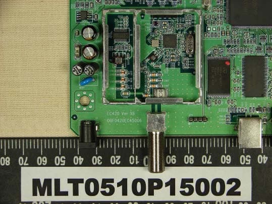
Click to zoom
Application Details
- Equipment Class
- JBP - Part 15 Class B Computing Device Peripheral
- Date of Grant
- Oct 23, 2005
- Application Purpose
- Original Equipment
- Date of Application
- Oct 23, 2005
- Equipment Note
- CABLE MODEM
- Company
- Turbocomm Tech Inc.
- Country
- Taiwan
Documents & Files
Document Text
Text extracted from the exhibit documents filed with the FCC. Open a document above to read the original.
Users Manual
EC420 User’s Manual Introduction Important Rules for safe Operation In addition to the careful attention devoted to quality standards in the manufacture of your TurboComm DOCSIS Cable modem, safety is a major factor in the design of every product. However, safety is your responsibility, too. This section lists important information that will help assure your enjoyment and proper use of the TurboComm Cable Modem and accessory equipment. Please read them carefully before operating and using your modem. Installation Read and Follow Instructions You should read all the safety and operating instructions before operating the modem. Follow all operating instructions. Retain Instructions You should save all the safety and operating instructions, for your future reference. Heed Warnings Comply with all warnings on the products and in the operating instructions. Check Power Sources Operate this product only from the type of power source indicated on the product’s marking label. If you are not sure of the type of power supplied to your home, consult your dealer or local power company. Be Careful of Overloading Do not overload wall outlets or extension cords, as this can result in a risk of fire or electric shock. Overloaded AC outlets, extension cords, frayed power cords, damaged or cracked wire insulation, and broken plugs are dangerous. They may result in a shock or fire hazard, Periodically examine the cord, and if its appearance indicated damage or deteriorated insulation, have it replaced by your service technician. Protect Power Cords Route power supply cords so that they are not likely to walked on or pinched by items placed upon or against them. Pay particular attention to cords where they are attached to plugs and convenience receptacles, and examine the point where they exit from the product. Check Ventilation Slots and openings in the enclosure are provided for ventilation to ensure reliable operation of the product and to protect it from overheating. Do not block or cover these openings. Never block these openings by placing the product on a bed, sofa, rug, or other similar surface. Never place this prodct near or over a radiator or heat register, or any other heat source (including amplifiers). Do not place this product in a built-in installation, such as a bookcase or equipment rack, unless you provide proper ventilation. Do Not Use Accessories Do not use attachments, unless they are recommended by TurboComm, as they may cause electrical or fire hazards, Use the Recommended AC Adaptor You must use the adaptor that comes with your TurboComm Cable Modem. Do Not Use Near Water Do not use this product near water – for example, near a bath tub, wash bowl, kitchen sink or laundry tub, in a wet basement or near a swimming pool, and the like. Do Not Place Near High Temperature Source – for example near a steamer, kitchen range fire, and the like. Use Caution in Mounting This Product Do not place this product on an unstable surface or support. The product may fall, causing serious injury to a child or adult, as well as serious damage to the product. Use Care in Moving Product and Cart Combinations Quick stops, excessive, force and uneven surfaces may cause the product and cart combination to overturn. Ground the Cable System Be sure that the outside cable system is grounded, so as to provide some protection against voltage surges and built-up static charges. Section 810 of the National Electric Code, ANSI/NFPA No. 70-1984(Section 54 of the Canadian Electrical Code, Part I) provides information with respect to proper grounding of the cable modem. Do not disconnect RF cable from your TurboComm Cable Modem while the power to your modem is on Use Unplug Power Before Cleaning Do not use liquid cleaner or aerosol cleaner. Use a damp cloth for cleaning. Keep Objects Out of Openings Never push objects of any kind into this product through openings, as they may touch dangerous voltage or “short-out” parts, which could result in a fire or electric shock. Never spill liquid on the product. Protect From Lightning For added protection for this product during a lightning storm, or when it is left unattended and unused for long periods of time, unplug it from the wall outlet, and disconnect the cable system. This will prevent damage to the product due to lightning and power line surges. Take at least 10 seconds between DC plug off and on. Service Do Not Remove Covers Do not attempt to service this product yourself, as opening or removing covers may expose you to dangerous voltage or other hazards. Refer all servicing to qualified service personnel. Unplug this product from the wall outlet carefully, as the AC adaptor may be hot. Refer servicing to Qualified Service Personnel Under the Conditions Listed Below When the power supply cord or plug is damaged. If liquid has been spilled or objects have fallen into the product. If the product has been exposed to rain or water. If the product doesn’t operate normally by following the operating instructions. Adjust only those controls that are covered by the operating instructions. If the product has been dropped or the cabinet has been damaged. When the product exhibits a distinct change in performance, such as the inability to perform basic functions – this indicates a need for service. Require Safety Check Upon completion of any service or repairs to this product, ask the service technician to perform safety checks recommended by TurboComm to determine that the product is in safe operating condition. Overview The modem provides you with high-speed data communications over the television cable network by following the widely accepted DOCSIS/MCNS standards being developed by the multimedia cable network system consortium. Those standards offer a combination of high performance and interoperability among many of the cable system operators in North America. Working of Cable modem Digital signals are represented by high and low electrical voltage levels. And how fast t…
Text truncated - open the document above for the full version.
Users Manual
EC420 User’s Manual Introduction Important Rules for safe Operation In addition to the careful attention devoted to quality standards in the manufacture of your TurboComm DOCSIS Cable modem, safety is a major factor in the design of every product. However, safety is your responsibility, too. This section lists important information that will help assure your enjoyment and proper use of the TurboComm Cable Modem and accessory equipment. Please read them carefully before operating and using your modem. Installation Read and Follow Instructions You should read all the safety and operating instructions before operating the modem. Follow all operating instructions. Retain Instructions You should save all the safety and operating instructions, for your future reference. Heed Warnings Comply with all warnings on the products and in the operating instructions. Check Power Sources Operate this product only from the type of power source indicated on the product’s marking label. If you are not sure of the type of power supplied to your home, consult your dealer or local power company. Be Careful of Overloading Do not overload wall outlets or extension cords, as this can result in a risk of fire or electric shock. Overloaded AC outlets, extension cords, frayed power cords, damaged or cracked wire insulation, and broken plugs are dangerous. They may result in a shock or fire hazard, Periodically examine the cord, and if its appearance indicated damage or deteriorated insulation, have it replaced by your service technician. Protect Power Cords Route power supply cords so that they are not likely to walked on or pinched by items placed upon or against them. Pay particular attention to cords where they are attached to plugs and convenience receptacles, and examine the point where they exit from the product. Check Ventilation Slots and openings in the enclosure are provided for ventilation to ensure reliable operation of the product and to protect it from overheating. Do not block or cover these openings. Never block these openings by placing the product on a bed, sofa, rug, or other similar surface. Never place this prodct near or over a radiator or heat register, or any other heat source (including amplifiers). Do not place this product in a built-in installation, such as a bookcase or equipment rack, unless you provide proper ventilation. Do Not Use Accessories Do not use attachments, unless they are recommended by TurboComm, as they may cause electrical or fire hazards, Use the Recommended AC Adaptor You must use the adaptor that comes with your TurboComm Cable Modem. Do Not Use Near Water Do not use this product near water – for example, near a bath tub, wash bowl, kitchen sink or laundry tub, in a wet basement or near a swimming pool, and the like. Do Not Place Near High Temperature Source – for example near a steamer, kitchen range fire, and the like. Use Caution in Mounting This Product Do not place this product on an unstable surface or support. The product may fall, causing serious injury to a child or adult, as well as serious damage to the product. Use Care in Moving Product and Cart Combinations Quick stops, excessive, force and uneven surfaces may cause the product and cart combination to overturn. Ground the Cable System Be sure that the outside cable system is grounded, so as to provide some protection against voltage surges and built-up static charges. Section 810 of the National Electric Code, ANSI/NFPA No. 70-1984(Section 54 of the Canadian Electrical Code, Part I) provides information with respect to proper grounding of the cable modem. Do not disconnect RF cable from your TurboComm Cable Modem while the power to your modem is on Use Unplug Power Before Cleaning Do not use liquid cleaner or aerosol cleaner. Use a damp cloth for cleaning. Keep Objects Out of Openings Never push objects of any kind into this product through openings, as they may touch dangerous voltage or “short-out” parts, which could result in a fire or electric shock. Never spill liquid on the product. Protect From Lightning For added protection for this product during a lightning storm, or when it is left unattended and unused for long periods of time, unplug it from the wall outlet, and disconnect the cable system. This will prevent damage to the product due to lightning and power line surges. Take at least 10 seconds between DC plug off and on. Service Do Not Remove Covers Do not attempt to service this product yourself, as opening or removing covers may expose you to dangerous voltage or other hazards. Refer all servicing to qualified service personnel. Unplug this product from the wall outlet carefully, as the AC adaptor may be hot. Refer servicing to Qualified Service Personnel Under the Conditions Listed Below When the power supply cord or plug is damaged. If liquid has been spilled or objects have fallen into the product. If the product has been exposed to rain or water. If the product doesn’t operate normally by following the operating instructions. Adjust only those controls that are covered by the operating instructions. If the product has been dropped or the cabinet has been damaged. When the product exhibits a distinct change in performance, such as the inability to perform basic functions – this indicates a need for service. Require Safety Check Upon completion of any service or repairs to this product, ask the service technician to perform safety checks recommended by TurboComm to determine that the product is in safe operating condition. Overview The modem provides you with high-speed data communications over the television cable network by following the widely accepted DOCSIS/MCNS standards being developed by the multimedia cable network system consortium. Those standards offer a combination of high performance and interoperability among many of the cable system operators in North America. Working of Cable modem Digital signals are represented by high and low electrical voltage levels. And how fast t…
Text truncated - open the document above for the full version.
Block Diagram
EE DD CC BB AA D D C C B B A A X-tal25MHz sh4 LM809RESET sh8 TE28F160CFLASH W986416DHSDRAM sh9 LED sh12 sh4 RS232CCN(2X3) EJTAG sh13 CN(2X7) TUNER sh14-16 CIRCUIT sh17 DC POWER 9V TNETC4401 UART B EJTAG X-tal_INRESETGPIO ETHERNETINTERFACEMII PORT EXTERNAL MEMORYINTERFACE PHYRTL8201 sh10 TR RJ45 sh11 USBB EXTERNALINTERRUPT JACK CIRCUIT 3.3V I2C I2C(SCL,SDA) sh13 sh10 sh10 sh4 sh17 USBINTERFACE X-tal25MHz sh4 USBCLKI DOCSISI/F Euro only VLYNQINTERFACE CODECINTERFACE PD0 Power Down Monitor AMPPD0 Euro:28.9MHz 1.5V5V sh15 F-CONN orMAX809STR X1 EC420 CABLE MODEM BLOCK DIAGRAM 317 Thursday, May 06, 2004 TitleSize Document Number Rev Date: Sheet of
External Photos
MAX LIGHT Technology Lab MAX LIGHT Technology Lab MAX LIGHT Technology Lab MAX LIGHT Technology Lab MAX LIGHT Technology Lab MAX LIGHT Technology Lab MAX LIGHT Technology Lab MAX LIGHT Technology Lab MAX LIGHT Technology Lab MAX LIGHT Technology Lab MAX LIGHT Technology Lab
ID Label/Location Info
Technology Lab Report Number: MLT0508P15001 FCC ID: TK4-05-WLM54AG Label Format: Label Position: Equipment Label 2.0cmX1.0cm Rear View This device complies with Part 15 of the FCC Rules. Operation is subject to the following two conditions: (1) This device may not cause harmful interference, and (2) This device must accept any interference received, including. Interference that may cause undesired operation. Model No: EC7000 FCC ID: N7ZEC420
Internal Photos
MAX LIGHT Technology Lab MAX LIGHT Technology Lab MAX LIGHT Technology Lab MAX LIGHT Technology Lab MAX LIGHT Technology Lab MAX LIGHT Technology Lab MAX LIGHT Technology Lab MAX LIGHT Technology Lab MAX LIGHT Technology Lab MAX LIGHT Technology Lab MAX LIGHT Technology Lab
Schematics
EE DD CC BB AA D D C C B B A A Active delay 240msec Debugber reset input Euro:PopulateUS:Do not populate (EINT*,SCC*,UART*,VRINQ_RD1)External pull-up/down does not need.Internal Pull-up/down is controled by SW. US:25.000MHzEURO:28.900MHz Active delay 200msecReset Threshold 2.93V NORMAL : SHORTDEBUG : OPEN Wide trace LABEL: WDENNML:SHORTDBG:OPEN C7 is optional for all bootconfiguration resistors on improvingRF issues in Euro Config X1 EC420 CABLE MODEM TNETC4401-1 417 Thursday, May 06, 2004 TitleSize Document Number Rev Date: Sheet of MIIMDIOMIIMDC MIICLK TDIEJTDOEJ DATALED0 MIIRXD0 TRST0EJ USBPULLE1 MIICRSMIIRXD1 MIITXD2 LINKLED0 VLRXD0 TMSEJ MIIRXD3MIIRXERMIITXC MIITXD0 VLCLK TINTEJ MIICOL MIITXEN TESTLED0 USBDP MIILINKMIIRXD2MIIRXDV PDMON0 TCKEJ USBMON MIIRXC MIITXD1 RS232CRX RESETEJ0 RS23 2CTX MIITXD3 CABLLED0 USBDM SYSRESET0 3P3V 3P3V 3P3V JP1HEADER 2X1 12 R3 1M S1 C7S1 NC R6 100 5% S1 C6 27PF/50V 5% NPO S1 R83.3K S1 C5 27PF/50V 5% NPO S1 X2 25.000MHz 49S 50PPM C4 0.1U/25V S1 R7 10K S1 R2 1M S1 LM809 U1 LM809-2.93 31 2 VCCGND RESET TNETC4401 1/4 miscellaneousEJTAG test portexternal interrupt GPIO UART-A interface USB interface MII port A VLYNQ/SCC Interface UART-B interface U2A TNETC4401 1618 189190167180168169172178179183184 4544434228252726 133134136137135164163165138142162144148147146145149150143158157156155125126127128129154 132023244647 188 3031293236343339414048 181185 15 131 XTAL_OUTXTAL_INTESTRESET EJTAGTDIEJTAGDINTEJTAGTDOEJTAGTMSEJTAGTCKEJTAGTRST0EJTAGTRST1EINT0EINT1GPIODGPIOCGPIOBGPIOAUARTA_RTSUARTA_RDUARTA_CTSUARTA_TD USBCLKI USBCLKO USBDM USBDP USBPULLE MIIDIOCLK MIIDIO MIIPHYCLK MIICOL MIICRS MIILINK MIIRCLK MIIRXD0MIIRXD1MIIRXD2MIIRXD3 MIIRXDVMIIRXER MIITCLK MIITXD0MIITXD1MIITXD2MIITXD3 VLYNQCLK VLYNQTXD0 VLYNQRXD0VLYNQRXD1 VLYNQTXD1 MIITXEN FOUT_PLLNCUARTB_RDUARTB_TDGPIOEGPIOFEINT3 SCCRING2SCCRING3SCCRING1SCCRING4 SCCDIN SCCCS SCCDCLK SCCDOUT SCCPCMCLK SCCPCMFS SCCCLKIN EJTAGSYSRST EINT2VSS VSS R1 47 S1 C3 15P/50V S1 NC X1 25.000MHz 49S 50PPM NC C2 15P/50V S1 NC C1 0.1U/25V S1 C8100PF/25V 10% X7R S1 R9 10K S1 MAX823 U3MAX823SEUK 1 5234 RESET VCCGNDMRWDI R10 10K S1 R4 47 S1 R5 47 S1 USBDM 11 TMSEJ 13 TCKEJ 13 TRST0EJ 13 MIIMDIO 10MIIMDC 10MIITXD3 10MIITXD2 10MIITXD0 10USBPULLE1 11 TESTLED0 12 DATALED0 12 MIICLK 10 MIIRXC 10MIIRXDV 10MIIRXD1 10MIICOL 10 TDOEJ 13 MIIRXD0 10MIICRS 10 TINTEJ 13 MIIRXD2 10MIILINK 10 TDIEJ 13 MIIRXD3 10 USBDP 11 USBMON 11 MIITXC 10MIIRXER 10 RESETEJ0 13 PDMON0 5 LINKLED0 12 CABLLED0 12 RS232CRX 13 RS23 2CTX 13 MIITXEN 10 SYSRESET0 8,10 MIITXD1 10 EE DD CC BB AA D D C C B B A A EA19 External 71 EA14 External memory interface is in normalmode of operation 1 EA20 62 EA11 ENDIAN 73 Wsdp EA13EA23Name 101 EA21 Wdhe EA15 6670 EMIF_R Watch dog timer disable bit is writable EA18 PLLBYPASS 61 FLSH[1:0] 0 64 PIN 63 Field 16Bit Flash width 67 Value EA16 PLL Mode 65 EMIF_TEST Boot from extarnal Flash EURO/M ANUAL 100 External memory interface is running at the fullspeed of the processor 74 Big Endian Select(default)VLYNQ CLK is inputBoot Location Select BOOTS 1:Watch dog timer di sabled after reset EA22EA12 Read external manual setting Boot Mode Settings EA17 Description EA10EA9 102103 DOCNOPLLSYSPLSEL 1(US) PLL in the DOCSIS is notbypassed EA8 108 1:Ether Clock is driven by the XTAL_IN EA6 AV_NOPLL EA7 USBPLSEL 110109 DEFAULT EA5 107 Use the above pin values to determin the boot optionsPower down non docsis PLLs.VCO isturned on. ETHCLKSEL 0:Ether Clock is driven by the USBCLKI1:System PLL is driven by the XTAL_IN0:System PLL is driven by the USBCLKI1:USB PLL1 is dri ven by the XTAL_IN 0:USB PLL1 is driven by the USBCLKI0:Watch dog timer enabled after reset 0010000001011 Device Configura tion: This resistors determines value, as a result of evaluating. 0(EURO)1(US)0(EURO)1(US)0(EURO)0(NML)1(OPT) VLYNQ CLK X1 EC420 CABLE MODEM TNETC4401-2 517 Thursday, May 06, 2004 TitleSize Document Number Rev Date: Sheet of TAGCS1AGCS1 IOUTPIOUTN INMINP PDMON0 3VA_PBGR 3P3V 3P3V C14NC S1 R13 47 S1 TNETC4401 2/4 TUNER interface U2B TNETC4401 198197174173176205177204 10 9 191192 23 4950 IOPIONAMPDAMPCAMPE REFMAMPPDREFPRSTEXTBGPADTAGCSAGCSAINPAINM IICMCLK IICMD C121000P/50V S1 C111U/16V S2 R14 47 S1 C13NC S1 R15 47 S1 C15NC S1 C91U/16V S2 C16NC S1 C101000P/50V S1 C17NC S1 R11 4.7K S1 R17 47 S1 R18NC S1 R20 NC S1 R124.7K S1 R16 47 S1 R1920K S1 1% AMPD1 15 I2CCLK 14 IOUTP 15 AMPC1 15 INM 16 TAGCS1 16 INP 16 IOUTN 15 I2CDATA 14 AMPE0 15 AGCS1 16 AMPPD0 15 PDMON0 4 EE DD CC BB AA D D C C B B A A (LSB) EMHIZ: "1" memory bus in High-Z (LSB) SYSTEM PLL SelectUS:1 E uro:0 (MSB) (MSB) Ether Clock Select US:1Euro:0USB PL L Select US:1 E uro:0 As for the row of data and an address lines, priority is given to a PCB layout.They are exchangeable if it is easy to a PCB layout. LABEL :SYS LABEL:USB LABEL:EtherLABEL:Wdhe Wdhe: Enable:0 Disable:1 Boot Mode Settings X1 EC420 CABLE MODEM TNETC4401-3 617 Thursday, May 06, 2004 TitleSize Document Number Rev Date: Sheet of SDRAS10SDCAS10 FLASHCS0 SDAWE10 EM10BE0 SDRAMCS0 SSOE10SDCKE11 EM10A15EM10A14EM10A17EM10A20 EM10A06EM10A22EM10A23EM10A18EM10A19EM10A17EM10A16EM10A13EM10A11EM10A10 SDRAMCLK EM10A15EM10A21EM10A20 EM10D02EM10D14EM10D04EM10D11EM10D12EM10D09EM10D00EM10D10EM10D05EM10D07EM10D03EM10D01EM10D13EM10D06EM10D15EM10D08 EM00D11 EM10D11 EM00D10EM00D09EM00D08 EM00D07 EM10D10EM10D09EM10D08 EM10D07 EM00D06EM00D05EM00D04EM00D03 EM10D06EM10D05EM10D04EM10D03 EM00D02EM00D01EM00D00 EM10D02EM10D01EM10D00 EM10BE1 EM10A12 EM10A08EM10A07 EM00D15EM00D06 EM10A21 EM00D02 EM10A16 EM00D08EM00D01EM00D13EM00D11EM00D05EM00D04EM00D09EM00D07EM00D10EM00D14EM00D12 EM00D00 EM10A14 EM00D03 EM10D15 EM00D15 EM10D12 EM00D13EM00D12EM00D14 EM10D14EM10D13 EM10A13EM10A19EM10A18 EM10A02EM10A03EM10A06EM10A11 EM00A22 EM10A08EM10A12EM10A00EM10A10EM10A07EM10A05EM10A04EM10A01 EM10A23EM10A22 EM10A09 EM10A09 EM00A03EM00A11EM00A04EM00A08EM00A06EM00A02EM00A12EM00A05EM00A01EM00A07EM00A00EM00A09 EM00A11EM00A09EM00A04EM00A06EM00A07EM00A01EM00A10EM00A02EM00A08EM00A03EM00A12EM00A00EM00A05 …
Text truncated - open the document above for the full version.
Test Report
Product : Cable Modem Applicant : TURBOCOMM TECH. INC. FCC ID : N7ZEC420 Model : EC7000 Report No. : MLT0510P15002 Test Date : Oct 14,2004 Test By Max Light Technology Co., Ltd. Room 5, 8F, No.125, Section 3 Roosevelt Road, Taipei, Taiwan., R.O.C. Tel: 886-2-2363-2447 Fax: 886-2-2363-2597 T T h h e e t t e e s s t t r r e e p p o o r r t t c c o o n n s s i i s s t t s s o o f f 2 2 7 7 p p a a g g e e s s i i n n t t o o t t a a l l . . I I t t m m a a y y b b e e d d u u p p l l i i c c a a t t e e d d c c o o m m p p l l e e t t e e l l y y f f o o r r l l e e g g a a l l u u s s e e w w i i t t h h t t h h e e a a l l l l o o w w a a n n c c e e o o f f t t h h e e a a p p p p l l i i c c a a n n t t . . I I t t s s h h a a l l l l n n o o t t b b e e r r e e p p r r o o d d u u c c e e d d e e x x c c e e p p t t i i n n f f u u l l l l , , w w i i t t h h o o u u t t t t h h e e w w r r i i t t t t e e n n a a p p p p r r o o v v a a l l o o f f o o u u r r l l a a b b o o r r a a t t o o r r y y . . MAX LIGHT MEASUREMENT REPORT Page: 2/272 Report Number: MLT0510P15002 FCC ID: N7ZEC420 Technology Lab Table of Contents : MAX LIGHT MEASUREMENT REPORT Page: 3/272 Report Number: MLT0510P15002 FCC ID: N7ZEC420 Technology Lab CERTIFICATION We here by verify that : The test data, data evaluation, test procedures and equipment configurations shown in this report were made in accordance with the procedures given in ANSI C63.4-2003. All test were conducted by MLT (Max Light Technology Co., Ltd) Room 5, 8F, No.125, Section 3 Roosevelt Road, Taipei, Taiwan, R.O.C Also, we attest to the accuracy of each. We further submit that the energy emitted by the sample EUT tested as described in the report is in compliance with Class B radiated and conducted emission limit of FCC Rules Part 15 Subpart B. EUT : Cable Modem Applicant : TURBOCOMM TECH. INC. 2F,No.,19-8, San Chong Road, Nan-Kang, Taipei 115 Taiwan ROC Manufacturer :TURBOCOMM TECH. INC. No.369,Sec.3,Chun Cheng East Road,Wu Chuan Tsun,Ta Yuan Hsiang,Tao Yuan Hsien,Taiwan,R.O.C. Model No : EC7000 FCC ID : N7ZEC420 Prepared by : Approved by : MAX LIGHT MEASUREMENT REPORT Page: 4/272 Report Number: MLT0510P15002 FCC ID: N7ZEC420 Technology Lab 1.1 Introduction The following measurement report is submitted on behalf of TURBOCOMM TECH. INC. In support of a Class B Digital Device certification in accordance with Part2 Subpart J and Part 15 Subpart A And B of the Commission’s and Regulations. 1.2 Description of EUT EUT : Cable Modem Applicant : TURBOCOMM TECH. INC. 2F,No.,19-8, San Chong Road, Nan-Kang, Taipei 115 Taiwan ROC Manufacturer : TURBOCOMM TECH. INC. No.369, Sec.3 Chun Cheng East Road, Wu Chuan Tsun, Ta Yuan Hsiang, Tao Yaun Hsien, Taiwan, R.O.C. Model No : EC7000 FCC ID : N7ZEC420 Power Type : Powered by AC Adaptor Model No.: AD-121AN; I/P: 120V, 60Hz, 20W O/P: 12VDC, 1Amp MAX LIGHT MEASUREMENT REPORT Page: 5/272 Report Number: MLT0510P15002 FCC ID: N7ZEC420 Technology Lab 1.3 Description of Support Equipment In order to construct the minimum system which required by the ANSI C63.4-2003, following equipments were used as the support units. Computer : IBM Model No. : 16W Serial No. : BNC345M FCC ID : FCC(DOC) Keyboard : IBM Model No. : KB-9930 Serial No. : 09N5395 FCC ID : FCC(DOC) Monitor : IBM Model No. : 10L6145 030 Serial No. : 23-092079 FCC ID : ARSCM569N Mouse : IBM Model No. : 0180-05N Serial No. : 23-092079 FCC ID : JNZ211220 Printer : PANASONIC Model No. : KX-P1080I Serial No. : 7CKAKE98933 FCC ID : ACJ5Z6KX-P10801 Modem : Askey (External Fax / Data Modem) Model No. : WS1414VE Serial No. : IAH-10811 FCC ID : H8N1414VE MAX LIGHT MEASUREMENT REPORT Page: 6/272 Report Number: MLT0510P15002 FCC ID: N7ZEC420 Technology Lab Power Supply PC Monitor Printer Modem Keyboard Mouse EUT RJ11C Cables USB Cable RS-232 To Other Ethernet Card To Cable Simulator 1.4 Configuration of System Under Test During testing the EUT(Cable Modem )’s LAN Ethernet port connected to the Remote Ethernet and USB port were connected USB port of IBM computer. A mouse was connected to the mouse port of IBM PC. And A keyboard was connected to the mouse port of IBM PC. And a printer was connected to the parallel port. An external modem connected the serial port and the external modem connected with two un-terminated telephone cables on the line and phone jack. TEST SITE MAX LIGHT MEASUREMENT REPORT Page: 7/272 Report Number: MLT0510P15002 FCC ID: N7ZEC420 Technology Lab 1.5 Test Procedure All measurements contained in this report were performed according to the techniques described in Measurement procedure ANSI C63.4-2003 "Measurement of un-Intentional Radiators." 1.7 General Test Condition The conditions under which the EUT operates were varied to determine their effect on the equipment's emission characteristics. The final configuration of the test system and the mode of operation used during these tests was chosen as that which produced the highest emission levels. However, only those conditions which the EUT was considered likely to encounter in normal use were investigated. The system's radiated and conducted emissions were investigated while the computer alternately transferred data to the EUT (1000 bytes). Run “Ping (IP Address -T –L 1000)” comment which sent a continuous stream of 1000 Bytes data to EUT and transferred data to and from the EUT was proven to worst case emissions. The system's physical layout and cabling was randomly arranged to ensure that maximum emission levels were attained. MAX LIGHT MEASUREMENT REPORT Page: 8/272 Report Number: MLT0510P15002 FCC ID: N7ZEC420 Technology Lab 2.1 General & Setup : The power line conducted emission measurements were performed in a shielded enclosure. The EUT was assembled on a wooden table which is 80 centimeters high, was placed 40 centimeters from the back wall and at least 1 meter from the sidewall. Power was fed to the EUT from the public utility power grid through a line filter and EMCO Model 3825/2 Line Im…
Text truncated - open the document above for the full version.
Test Setup Photos
MAX LIGHT MEASUREMENT REPORT Page: 17/272 Report Number: MLT0510P15002 FCC ID: N7ZEC420 Technology Lab 3.3 Test Configuration: Front View of The Test Configuration MAX LIGHT MEASUREMENT REPORT Page: 18/272 Report Number: MLT0510P15002 FCC ID: N7ZEC420 Technology Lab Rear View of The Test Configuration MAX LIGHT MEASUREMENT REPORT Page: 19/272 Report Number: MLT0510P15002 FCC ID: N7ZEC420 Technology Lab Front View of The Test Configuration (VERTICAL) MAX LIGHT MEASUREMENT REPORT Page: 20/272 Report Number: MLT0510P15002 FCC ID: N7ZEC420 Technology Lab Rear View of The Test Configuration (VERTICAL)
Contact Information
Applicant
Ken Hsu(Senior Engineer)
Test Firm
Max Light Technology Co., Ltd.Jesse Tien
Technical Specifications
| # | Rule Parts | Frequency Range | Power Output |
|---|---|---|---|
| 1 | 15B | - | - |
Other Applications from Turbocomm Tech Inc.

N7ZRT-900W
Jun 07, 2006Wireless AP
Equipment Class
DTS - Digital Transmission System
N7ZWVM-1101
May 11, 2006Wireless Video Module
Equipment Class
NII - Unlicensed National Information Infrastructure TX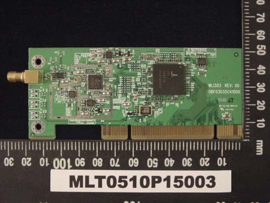
N7ZWLI303
Dec 01, 2005WIRELESS LAN 802.11/b,g
Equipment Class
DTS - Digital Transmission System
N7ZRT-710S
Jan 01, 2002Broadband Sharing Router
Equipment Class
JBP - Part 15 Class B Computing Device Peripheral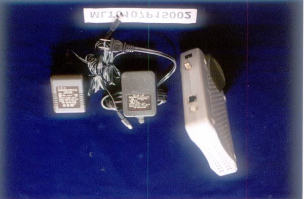
N7ZEC280
Nov 29, 2001DOCSIS Cable Modem
Equipment Class
JBP - Part 15 Class B Computing Device Peripheral