N7ZWLI303WIRELESS LAN 802.11/b,g
Turbocomm Tech Inc.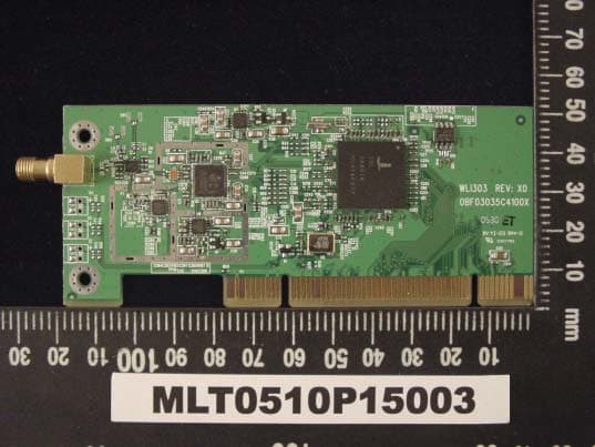
Click to zoom
Application Details
- Equipment Class
- DTS - Digital Transmission System
- Date of Grant
- Dec 01, 2005
- Application Purpose
- Original Equipment
- Date of Application
- Dec 01, 2005
- Equipment Note
- WIRELESS LAN 802.11/b,g
- Frequency Range
- 2412.00000000 - 2462.00000000
- Company
- Turbocomm Tech Inc.
- Country
- Taiwan
Documents & Files
Document Text
Text extracted from the exhibit documents filed with the FCC. Open a document above to read the original.
Users Manual
Wireless LAN IEEE802.11g PCI Card User Manual Table of Contents FCC Information ........................................................................... I Chapter 1 About Wireless LAN PCI Card.......................................... 1 1-1 Features and Benefits .................................................................. 1 1-2 Applications ....................................................................... 1 1-3 Product Kit ................................................................................ 2 Chapter 2 Getting Started............................................................... 3 2-1 Before Installation........................................................................ 3 2-2 Insert the 802.11g Wireless LAN PCI Card .......................................... 3 Chapter 3 Install Driver for Windows ............................................. 4 3-1 Setup IEEE802.11g PCI Wireless LAN Card for Windows XP..................... 4 3-2 Setup IEEE802.11g PCI Wireless LAN Card for Windows 2000 .................. 7 3-3 Setup IEEE802.11g PCI Wireless LAN Card for Windows ME .................. 11 3-4 Setup IEEE802.11g PCI Wireless LAN Card for Windows 98SE ............... 13 Limited Warranty ........................................................................ 16 Glossary........................................................................... 17 FCC Information This device, IEEE 802.11g PCI Wireless LAN Card, complies with Part 15 of the FCC rules. Operation is subject to the following two conditions: (1) this device may not cause harmful interference, and (2) this device must accept any interference received; including interference that may cause undesired operation. Federal Communications Commission (FCC) Statement This Equipment has been tested and found to comply with the limits for a Class B digital device, pursuant to Part 15 of the FCC rules. These limits are designed to provide reasonable protection against harmful interference in a residential installation. This equipment generates, uses and can radiate radio frequency energy and, if not installed and used in accordance with the instructions, may cause harmful interference to radio communications. However, there is no guarantee that interference will not occur in a particular installation. If this equipment does cause harmful interference to radio or television reception, which can be determined by turning the equipment off and on, the user is encouraged to try to correct the interference by one or more of the following measures: - Reorient or relocate the receiving antenna. - Increase the separation between the equipment and receiver. - Connect the equipment into an outlet on a circuit different from that to which the receiver is connected. - Consult the dealer or an experienced radio/TV technician for help. Warning: Changes or modifications to this unit not expressly approved by the party responsible for compliance could void the user authority to operate the equipment. Tested to comply with FCC standard. FOR HOME OR OFFICE USE. FCC RF Radiation Exposure Statement: 1. This equipment complies with FCC RF radiation exposure limits set forth for an uncontrolled environment, under 47 CFR 2.1093 paragraph (d)(2). 2. This Transmitter must not be co-located or operating in conjunction with any other antenna or transmitter. i The IEEE 802.11g PCI Wireless LAN Card has been tested to the FCC exposure requirements (Specific Absorbtion Rate). The antenna(s) used for this transmitter must be installed to provide a separation distance of at least 20 cm from all persons. ii Chapter 1 About Wireless LAN PCI Card The IEEE 802.11g PCI Wireless LAN Card is a standard PCI Card that fits into any standard PCI slot in a desktop. The IEEE 802.11g PCI Wireless LAN Card is an enhanced high-performance, that supports high-speed wireless networking at home, or at office. The IEEE 802.11g PCI Wireless LAN Card is able to communicate with any 802.11b and 802.11g compliant products. 1-1 Features and Benefits 1. Supports 1, 2, 5.5, 11 Mbps and up to 54Mbps data rate. 2. Working range up to 800 ft. in an open environment. 3. Seamless connectivity to wired Ethernet and PC network LAN’s augments existing networks quickly and easily. 4. Greater flexibility to locate or move networked PCs. 5. Wireless connection without the cost of cabling. 6. Easy to install and user friendly, just Plug and Play. 7. Low power consumption. 8. Supports a variety of operating systems (Win98SE/ME/2000/XP) 9. 64-bit and 128-bits WEP encryption capable. 10. Provides Window-based Diagnostic Tools, most notably, Site Survey, Link Quality Test and Access Point Browser. 1-2 Applications IEEE 802.11g PCI Wireless LAN Card offers a fast, reliable, cost-effective solution for wireless client access to the network in applications like these: 1. Remote access to corporate network information E-mail, file transfer and terminal emulation. 2. Difficult-to-wire environments Historical or old buildings, asbestos installations, and open area where wiring is difficult to deploy. 3. Frequently changing environments Retailers, manufacturers and those who frequently rearrange the workplace and change 4. Temporary LANs for special projects or peak time • Trade shows, exhibitions and construction sites where a temporary network will be practical. • Retailers, airline and shipping companies need additional - 1 - workstations during peak period. • Auditors requiring workgroups at customer sites. 5. Access to database for mobile workers Doctors, nurses, retailers, accessing their database while being mobile in the hospital, retail store or office campus. 6. SOHO (Small Office and Home Office) users SOHO users need easy and quick installation of a small computer network. 7. High security connection The secure wireless network can be installed quickly and provide flexibility. 1-3 Product Kit IEEE 802.11g PCI Wireless LAN Card comes with the following items. Please go through each it…
Text truncated - open the document above for the full version.
External Photos
MAX LIGHT Technology Lab MAX LIGHT Technology Lab MAX LIGHT Technology Lab
ID Label/Location Info
Technology Lab Label Format: Label Position: Equipment Label 2.0cmX1.0cm Rear View This device complies with Part 15 of the FCC Rules. Operation is subject to the following two conditions: (1) This device may not cause harmful interference, and (2) This device must accept any interference received, including. Interference that may cause undesired operation. Model No: ELI303 FCC ID: N7ZWLI303
Internal Photos
MAX LIGHT Technology Lab MAX LIGHT Technology Lab MAX LIGHT Technology Lab
Operational Description
Theory description 5GHz VCO ISL3084 Power Amp ISL3980 Low Pass Filter Diversity Antennas BPF AND BALUN Band Pass Filter HOST Balun RF/IF Transceiver ISL3686 TR_SW TR_SW# Loop Filter 40MHz Clock Diversity T/R switch AS218_321 BBP(Baseband Processor)/MAC ISL3886 Serial EEPROM Liner Regulator ISL6414 1. Firmware implements the full IEEE 802.11/b/g Wireless LAN MAC pro-tocols. Internal WEP Engine allows 64 or 128 bit Encryption. Data Rates: 1, 2, 5.5, 6, 9, 11, 12, 18, 24, 36, 48, & 54Mbps. Modulation OFDM with BPSK, QPSK, 16QAM, 64QAM. DBPSK, DQPSK, CCK. Convolutional coding and interleaving on all OFDM rates。 2. The ISL3886 allows the PCI Configuration Registers, the CIS, and a small firmware image to be transferred from an off-chip serial non-volatile memory device to on-chip RAM after a system reset. 3. Front End Circuitry The input signal to the radio is received through the antenna 4. Low Noise Amplifier (LNA) and Up/Down Converter The LNA is a fixed gain amplifier and is preceded by a 25dB attenuator controlled by the LNA High/Low pin 5. Receive Amplifier and Automatic Gain Control These analog differential outputs are fed through separate I and Q Low Pass Filters to establish the bandwidth of the system, attenuate out-of-band signals and prepare the signals for baseband processing 6. Transmit Signal Path GeneralData from the host computer is sent to the MAC through the PCI interface 7. the transmitter supports two modulation processes, one for CCK modulation and the other for OFDM.
Operational Description
Data Sheet 05/11/28 WLI303 SPEC for FCC application.doc TurboComm 2.4GHz Wireless LAN IEEE 802.11b/g Wireless LAN PCI Card with Nitro XM Model Number: WLI303 General Descriptions TurboComm’s WLI303 is a 2.4GHz wireless LAN add-on-card which plug into the PCI slot of desktop computer system. Offering easy installation and cost-effective connection for Wireless network service. With the performance enhancement of Nitro XM, the WLI303 can achieve wireless speeds up to 140Mbps 1 in a pure Nitro XM environment through the use of new wireless techniques such as Compression, Concatenation, Piggyback Acknowledgements, Packet Bursting and Direct Link mode. This provides a bandwidth large enough to handle video/audio streaming and Video on Demand (VoD) applications. All TurboComm products are made in TL9000 approved factory. WLI303 Wireless PCI Card complies with FCC part15 regulations and CE approval. Features and Benefits • 32-bit PCI V2.2 compliant and plug and play compatible for easy configuration, plug-and-play installation • 802.11g industry standard • Use popular 2.4GHz frequency band • Backwards compatible with existing 802.11b wireless devices • Performance enhancement up to 140Mbps 1 by Nitro XM • Compression - Compress data allowing faster throughput • Concatenation - Combines multiple small packets of data into a “jumbo” 802.11 packet – improves network efficiency - Highly effective when used with Compression • Piggyback Acknowledgements - Eliminates redundant messages • Packet Bursting - Delivers throughput enhancement in both mixed and g-only networks • Direct Link - Enables an automatic, secure, high-speed link directly between wireless clients while maintaining communications with the Access Point • Advanced security with WPA, TKIP and Pre-Shared Key function support • Runs Windows ® 98SE, 2000, ME, XP Data Sheet 05/11/28 WLI303 SPEC for FCC application.doc Specifications Standards • IEEE 802.11 • IEEE 802.11b • IEEE 802.11g Bus Type PCI 2.2 Media Access Control Protocol CSMA/CA (Carrier Sense Multiple Access with Collision Avoidance) with Random Backoff Network Architecture Types • Ad-Hoc mode (Peer-to-Peer) • Infrastructure mode (Access Point) Frequency Range 2.412 ~ 2.484 GHz Operating Channels • US (FCC): 11 • Europe (ETSI): 13 • Canada (DOC): 11 Network Transfer Rate 1 /Modulation Technique • 802.11b 11Mbps, 5.5Mbps: CCK 2Mbps: QPSK 1Mbps: BPSK • 802.11g 54Mbps, 48Mbps, 36Mbps, 24Mbps, 18Mbps, 12Mbps, 9Mbps, 6Mbps: OFDM (orthogonal Frequency Division Multiplexing) Receiver Sensitivity • 54Mbps OFDM, 10% PER: -70dBm • 48Mbps OFDM, 10% PER: -72dBm • 36Mbps OFDM, 10% PER: -77dBm • 24Mbps OFDM, 10% PER: -81dBm • 18Mbps OFDM, 10% PER: -85dBm • 12Mbps OFDM, 10% PER: -88dBm • 11Mbps CCK, 8% PER: -88dBm • 9Mbps OFDM, 10% PER: -89dBm • 6Mbps OFDM, 10% PER: -91dBm • 5.5Mbps CCK, 8% PER: -91dBm • 2Mbps QPSK, 8% PER: -92dBm • 1Mbps BPSK, 8% PER: -96dBm Transmitter output power • 12 dBm (1dBm) Security • 64/128-bit WEP data encryption • EAP - MD5-Challenge, LEAP, TTLS, PEAP, TLS • WPA-PSK/WPA-None (Encryption level: TKIP/AES) Antenna External Dipole antenna with detachable reverse SMA connector Emission (EMI) FCC part 15 Class B and CE Class B Mechanical • Size (app.): 120mm(length) x 51mm (width) x 11mm (height) • Net Weight (app.): 65 g Environmental • Operating temperature 0°C ~ 50°C • Humidity 5 % ~ 95 % (non-condensing) • Storage temperature -20°C ~ 60°C Supported OS Windows 98SE, ME, 2000 and XP Sales and Service Points Headquarters Tu r b o C o m m Te c h . I n c . 2F, No.19-8, San Chong Road, Nan Kong, Taipei 115, Taiwan, R.O.C. Tel: +886-2-2655-1618 Fax: +886-2-26551619 Sales contact: [email protected] 1 Maximum wireless signal rate derived from IEEE standard 802.11g specifications. Actual data throughput will vary. Network conditions and environment factors lower actual data throughput rate. * Microsoft, Windows, and Windows XP are either registered marks or trademarks of Microsoft Corporation. All other trademarks are the property of their respective owners. * Specifications are subject to change without notice.
RF Exposure Info
MAX LIGHT MEASUREMENT REPORT Report Number: MLT0510P15003 FCC ID: N7ZWLI303 Technology Lab M M a a x x i i m m u u m m P P e e r r m m i i s s s s i i b b l l e e E E x x p p o o s s u u r r e e 1. Introduction In this document, we try to prove the safety of radiation harmfulness to the human body for our product. The limit for Maximum Permissible Exposure (MPE) specified in FCC 1.1310 is followed. The Gain of the antenna used in this product is measured in a Fully Anechoic Chamber (FAC) calibrated for antenna measurement in MLT, and also the maximum total power input to the antenna is measured. Through the Friis transmission formula and the maximum gain of the antenna, we can calculate the distance, away from the product, where the limit of MPE is reached. Although the Friis transmission formula is a far field assumption, the calculated result of that is an over-prediction for near field power density. We will take that as the worst case to specify the safety range. 2. Description of EUT EUT : Wireless LAN 802.11/b.g Applicant : TURBOCOMM TECH. INC. 2F,No.,19-8, San Chong Road, Nan-Kang, Taipei 115 Taiwan ROC Manufacturer : TURBOCOMM TECH. INC. No.369,Sec.3,Chun Cheng East Road,Wu Chuan Tsun,Ta Yuan Hsiang,Tao Yuan Hsien,Taiwan,R.O.C. Model No : WLI303 FCC ID : N7ZWLI303 MAX LIGHT MEASUREMENT REPORT Report Number: MLT0510P15003 FCC ID: N7ZWLI303 Technology Lab 3. Classification The antenna of this product, under normal use condition, is at least 20cm away from the body of the user. Warning statement to the user for keeping at least 20cm or more separation distance with the antenna should be included in users manual. So, this device is classified as Mobile Device. The antenna(s) used for this transmitter must be installed to provide a separation distance of at least 20 cm from all persons. 4. Friis Formula Friis transmission formula : Pd = (Pout*G) / (4*pi*r^2) Where Pd = power density in mW/cm^2 Pout = output pwer to antenna in Mw G = gain of antenna in linear scale Pi = 3.1416 R = distance between observation point and center of the radiator in cm 5. Test Result: 802.11b Max RF Power (dBm) TX Antenna Gain (dBi) Testing Result (mW/cm^2) MPE Limit (mW/cm^2) 11.67 2.0 0.0058 1 802.11g Max RF Power (dBm) TX Antenna Gain (dBi) Testing Result (mW/cm^2) MPE Limit (mW/cm^2) 8.39 2.0 0.0027 1
Schematics
1 2 34 ABCD 4 3 2 1 D CBA Scale Sheet Size FCSM No. DWG No. Rev 1 of 3 B WLI303 V1 TURBOCOMMPCI 802.11g WLAN adapter 1.2VREFFSADOFFLNA-HLBB-OVLDIOFFSET+IOFFSET-QOFFSET+QOFFSET-BB-AGC+BB-AGC-RXI+RXI-RXQ-RXQ+TXQ+TXI+TXI-TXQ-PA-DETTX-IQ-DETTX-AGCSYNDATASYNCLKSYN-LEPE2PE12GPABIASLOCK-DETCANT-SW+ANT-SW-OSC-EN40MHz macmac.Sch OSC-EN 40MHz RXI+ RXI- RXQ+ RXQ- 1.2VREF TXQ+ TXQ- TXI+ TXI- LOCK-DETC BB-OVLD BB-AGC+ BB-AGC- FSADOFF IOFFSET- IOFFSET+ QOFFSET- QOFFSET+ PE2 LNA-HL SYNDATA SYNCLK SYN-LE PE1 TX-AGC TX-IQ-DET 2GPABIAS PA-DET ANT-SW+ ANT-SW- FrontFront.Sch 1 2 3 4 5 6 ABCD 6 5 4 3 2 1 D CBA Scale Sheet Size FCSM No. DWG No. Rev 2 of 3 B WLI303 V1 TURBOCOMMPCI 802.11g WLAN adapter -12V B1 TCK B2 GND B3 TDD B4 +5V B5 +5V B6 INTB# B7 INTD# B8 PRSNT1# B9 Reserved B10 PRSNT2# B11 Reserved B14 GND B15 CLK B16 GND B17 REQ# B18 +V_I/O B19 AD31 B20 AD29 B21 GND B22 AD27 B23 AD25 B24 +3.3V B25 C/BE3# B26 AD23 B27 GND B28 AD21 B29 AD19 B30 +3.3V B31 AD17 B32 C/BE2# B33 GND B34 IRDY# B35 +3.3V B36 DEVSEL# B37 GND B38 LOCK# B39 PERR# B40 +3.3V B41 SERR# B42 +3.3V B43 C/BE1# B44 AD14 B45 GND B46 AD12 B47 AD10 B48 M66EN B49 AD8 B52 AD7 B53 +3.3V B54 AD5 B55 AD3 B56 GND B57 AD1 B58 +V_I/O B59 ACK64# B60 +5V B61 +5V B62 TRST# A1 +12V A2 TMS A3 TDI A4 +5V A5 INTA# A6 INTC# A7 +V_I/O A8 Reserved A9 +5V A10 Reserved A11 VAUX A14 RST# A15 +V_I/O A16 GNT# A17 GND A18 PME A19 AD30 A20 +3.3V A21 AD28 A22 AD26 A23 GND A24 AD24 A25 IDSEL A26 +3.3V A27 AD22 A28 AD20 A29 GND A30 AD18 A31 AD16 A32 +3.3V A33 FRAME# A34 GND A35 TRDY# A36 GND A37 STOP# A38 +3.3V A39 Reserved A40 Reserved A41 GND A42 PAR A43 AD15 A44 +3.3V A45 AD13 A46 AD11 A47 GND A48 AD9 A49 C/BE0# A52 +3.3V A53 AD6 A54 AD4 A55 GND A56 AD2 A57 AD0 A58 +V_I/O A59 REQ64# A60 +5V A61 +5V A62 P1Cardbus MINI PCI3 CBE0 E17 CBE1 D15 CBE2 B12 CBE3 D9 CINTA B5 CRST C5 CFRAME C10 CTRDY C13 CIRDY C11 CREQ C3 CSERR B13 CSTOP B14 CDEVSEL C14 CPERR D14 CGNT B3 PCI-CLK A5 CPAR A12 CIDSEL C9 CPME C4 VDD-IO A2 VDD-IO A4 GNDD B10 GNDD B15 GNDD C8 GNDD D6 GNDD D7 GNDD D12 GNDD D18 GNDD E2 GNDD N17 GNDD G18 GNDD H4 GNDD J3 GNDD J19 GNDD L17 GNDD M2 GNDD T1 GNDD T4 LF-XTALIN W1 LF-XTALOUT U2 CLKIN40 P20 OSCENABLE N18 GRESET B2 ANTSEL L4 ANTSEL M1 COMPIQ W14 COMPRX W17 COMPTX U16 COMPPABIAS R18 VREF Y10 IREF W11 PCI_AD0 F19 PCI_AD1 F17 PCI_AD2 F18 PCI_AD3 G17 PCI_AD4 D19 PCI_AD5 E19 PCI_AD6 E18 PCI_AD7 D20 PCI_AD8 C19 PCI_AD9 B16 PCI_AD10 A19 PCI_AD11 B17 PCI_AD12 C16 PCI_AD13 C17 PCI_AD14 A15 PCI_AD15 C15 PCI_AD16 C12 PCI_AD17 B9 PCI_AD18 D11 PCI_AD19 D13 PCI_AD20 A9 PCI_AD21 A8 PCI_AD22 B11 PCI_AD23 D10 PCI_AD24 B7 PCI_AD25 C6 PCI_AD26 B8 PCI_AD27 C7 PCI_AD28 D8 PCI_AD29 D5 PCI_AD30 B6 PCI_AD31 B4 PCI_CLKRUN A1 TEST0 L20 TEST1 K19 TEST2 K17 TEST3 K18 TEST4 J18 TEST5 H20 TEST6 J17 TEST7 H19 TEST8 G20 TEST9 H18 TEST10 G19 TEST11 H17 TESTCLK80 L19 TESTCLK44 M19 CLKOUT M20 COMPIOFF U10 UARTSIN R4 UARTSOUT F4 FAAMODE G3 FAA-HRD D2 LED0 P4 LED1 R2 FAA-LED J1 SER-DATA K3 SER-CLK K2 PLL-LD M4 RADIO-PE L3 T/R-SW N4 T/R-SW M3 PE2 N2 PA-PE2G N3 SYNTH-DATA P2 SYNTH-CLK N1 SYNTH-LE P3 PA-PE5G F1 PE1 T2 2GPABIAS U20 FSADPABIAS T19 LNA H/L P19 IOFFSET+ Y9 IOFFSET- V10 QOFFSET- W8 QOFFSET+ Y7 BB-AGC+ Y18 BB-AGC- V16 RXI+ Y11 RXI- W12 RXQ+ Y12 RXQ- Y13 TXI+ W13 TXI- Y14 TXQ+ Y15 TXQ- Y16 PA-DET Y17 TX-IQ-DET V15 TX-IFAGC W18 FSADTX V17 FSADRX Y19 FSADOFF W9 FSADIQ U13 LOOP80 V20 LOOP44 R17 TDO W5 TDI V5 TCK U6 TMS W4 TRST Y2 HB-LB R3 GP1-2 E3 GP2-3 K4 GP2-4 J2 GP2-5 H2 GP2-6 J4 GP2-7 H3 GP2-8 G2 GP2-10 L2 GP2-11 F2 GP2-12 G4 GP2-13 F3 TMSEL0 V6 TMSEL1 U7 TMSEL2 V7 TMSEL3 Y5 GNDD V1 GNDD V4 GNDD W6 GNDD0 Y6 GNDD1 Y20 GNDA V9 GNDA V12 GNDA V14 GNDA W19 GNDA P17 GNDA T18 GNDA W7 GNDA V18 VDD-IO A6 VDD-IO A10 VDD-IO A13 VDD-IO A16 VDD-IO A18 VDD-IO C20 VDD-IO D1 VDD-IO E20 VDD-IO G1 VDD-IO J20 VDD-IO K1 VDD-IO L18 VDD-IO P1 VDD-IO R20 VDD-IO U1 VDD-IO U3 VDD-IO Y3 VDD-CORE A3 VDD-CORE A7 VDD-CORE A11 VDD-CORE A14 VDD-CORE A17 VDD-CORE B20 VDD-CORE C1 VDD-CORE E1 VDD-CORE F20 VDD-CORE H1 VDD-CORE K20 VDD-CORE L1 VDD-CORE M18 VDD-CORE R1 VDD-CORE T3 VDD-CORE Y4 VDDA1 V8 VDDA2 W10 VDDA3 V11 VDDA4 U12 VDDA5 W16 VDDA6 P18 VDDAPLL U19 VDDD1 U17 VDDD0 U8 RX-IF-DET W15 U8 ISL3880 A0 1 A1 2 A2 3 GND 4 SDA 5 SCL 6 WP 7 VCC 8 U18AT24C64 12 R461k 12 C680.1u VCCS AD0AD1AD2AD3AD4AD5AD6AD7AD8AD9AD10AD11AD12AD13AD14AD15AD16AD17AD18AD19AD20AD21AD22AD23AD24AD25AD26AD27AD28AD29AD30AD31 AD0 AD1 AD2 AD3 AD4 AD5 AD6 AD7AD8 AD9 AD10 AD11 AD12 AD13 AD14 AD15AD16 AD17 AD18 AD19 AD20 AD21 AD22 AD23 AD24 AD25 AD26 AD27 AD28 AD29 AD30 AD31 RESET 1 CT 2 SHDN 3 SHDN3 4 OUT3 5 CC3 6 GND3 7 GND 8 CC2 9 OUT2 10 CC1 11 OUT1 12 VIN 13 VIN 14 FAULT 15 RESET 16 PADDLE 17 U7ISL6411 RESET RESET U8-B2 +3.3V 12 C2390.1u 12 C3610u 3.3V 3.3V 12 C2410.1u 12 C4010u G 1 S 2 D 3 M1 IRLML6401 B 1 C 3 E 2 Q20MMBT222 1 2 R218 20k 1 2 R230-NC 1 2 R21082k VCCS 12 C3270.01u 12 C32433n 12 C3710u 1 2 R240 1 2 R19310 12 C2400.1u 12 C3810u 12 C3910u VCCB VCCC 2.84V 12 C32533n 12 C32333n 1.8V 12 C3510u 12 C3410u VCCA 2.84V 12 C610.1u 12 C600.1u 12 C590.1u 12 C580.1u 12 C570.1u 12 C560.1u 12 C550.1u 12 C540.1u 12 C530.1u 12 C520.1u 12 C510.1u 12 C620.1u 12 C630.1u 12 C640.1u 1.8V 1.8V 12 C2440.1u 12 C2490.1u 12 C2500.1u 12 C2510.1u 12 C2520.1u 12 C2530.1u 12 C2540.1u 12 C2550.1u 12 C2560.1u 12 C2570.1u 12 C2580.1u 12 C2590.1u 12 C2600.1u 12 C2610.1u 12 C2620.1u 12 C2630.1u VCCS VCCA 12 C690.1u 12 C700.1u 12 C710.1u 12 C720.1u 12 C670.1u 12 C3310u 12 C650.1u 12 C660.1u 1 2 R150 1 2 R160 VCCA INTA INTA RST RST FRAME FRAME TRDY TRDY IRDY IRDY REQ REQ SERR SERR STOP STOP DEVSEL DEVSEL PERR PERR GNT GNT CLK CLK 1 2 R2170 PAR PAR IDSEL IDSEL PME PME 1 2 R30 0-NC CLKRUN CLKRUN 1 2 R17910k-NC TP TP5 TP TP13 TP TP6 TP TP14 TP TP7 TP TP15 TP TP8 TP TP16 TP TP9 TP TP17 TP TP10 TP TP18 TP TP11 TP TP19 TP TP12 1 2 C242 0.047u-NC 1 2 C247 0.1u-NC 1 2 C245 0.1u-NC 1 2 C243 0.1u-NC 1 2 C248 0.1u-NC VCCA 12 R22312.1k 12 C2460.1u 1.2VREF TP TP30 TP TP31 BE3 BE3 BE0 BE0 BE1 BE1 BE2 BE2 LED0LED1FAA-LED 12 R17210k VCCS FAA-HRD FAA-HRD 1 2 R17310k 1 2 R17410k-NC VCCS 12 R…
Text truncated - open the document above for the full version.
Test Report
P P a a r r t t 1 1 5 5 S S u u b b p p a a r r t t B B & & C C ( ( 1 1 5 5 . . 2 2 4 4 7 7 ) ) Product : Wireless LAN 802.11/b.g Applicant : TURBOCOMM TECH. INC. FCC ID : N7ZWLI303 Model No. : WLI303 Report No. : MLT0510P15003 Issue Date : Nov 18, 2005 Test By Max Light Technology Co.,Ltd. Room 5, 8F, No.125, Section 3 Roosevelt Road, Taipei, Taiwan., R.O.C. Tel: 886-2-2363-2447 Fax: 886-2-2363-2597 T T h h e e t t e e s s t t r r e e p p o o r r t t c c o o n n s s i i s s t t s s o o f f 1 1 0 0 2 2 p p a a g g e e s s i i n n t t o o t t a a l l . . I I t t m m a a y y b b e e d d u u p p l l i i c c a a t t e e d d c c o o m m p p l l e e t t e e l l y y f f o o r r l l e e g g a a l l u u s s e e w w i i t t h h t t h h e e a a l l l l o o w w a a n n c c e e o o f f t t h h e e a a p p p p l l i i c c a a n n t t . . I I t t s s h h a a l l l l n n o o t t b b e e r r e e p p r r o o d d u u c c e e d d e e x x c c e e p p t t i i n n f f u u l l l l , , w w i i t t h h o o u u t t t t h h e e w w r r i i t t t t e e n n a a p p p p r r o o v v a a l l o o f f o o u u r r l l a a b b o o r r a a t t o o r r y y . . MAX LIGHT MEASUREMENT REPORT Page: 2/102 Report Number: MLT0510P15003 FCC ID: N7ZWLI303 Technology Lab Table of Contents : MAX LIGHT MEASUREMENT REPORT Page: 3/102 Report Number: MLT0510P15003 FCC ID: N7ZWLI303 Technology Lab CERTIFICATION We here by verify that : The test data, data evaluation, test procedures and equipment configurations shown in this report were made in accordance with the procedures given in ANSI C63.4: 2003. All test were conducted by MLT (Max Light Technology Co., Ltd) Room 5, 8F, No.125, Section 3 Roosevelt Road, Taipei, Taiwan, R.O.C Also, we attest to the accuracy of each. We further submit that the energy emitted by the sample EUT tested as described in the report is in compliance with Class B radiated and conducted emission limit of FCC Rules Part 15 Subpart B & C (15.247). EUT : Wireless LAN 802.11/b.g Applicant : TURBOCOMM TECH. INC. 2F,No., 19-8, San Chong Road, Nan-Kang, Taipei 115 Taiwan ROC Manufacturer : TURBOCOMM TECH. INC. No.369, Sec.3,Chun Cheng East Road,Wu Chuan Tsun, Ta Yuan Hsiang, Tao Yuan Hsien,Taiwan,R.O.C. Model No : WLI303 FCC ID : N7ZWLI303 Prepared by : Approved by : MAX LIGHT MEASUREMENT REPORT Page: 4/102 Report Number: MLT0510P15003 FCC ID: N7ZWLI303 Technology Lab 1.1 Introduction The following measurement report is submitted on behalf of TURBOCOMM TECH. INC. In support of a Class B Digital Device certification in accordance with Part2 Subpart J and Part 15 Subpart A And B&C of the Commission’s and Regulations. 1.2 Description of EUT EUT : Wireless LAN 802.11/b.g Applicant : TURBOCOMM TECH. INC. 2F,No., 19-8, San Chong Road, Nan-Kang, Taipei 115 Taiwan ROC Manufacturer : TURBOCOMM TECH. INC. No.369, Sec.3, Chun Cheng East Road, Wu Chuan Tsun, Ta Yuan Hsiang, Tao Yuan Hsien, Taiwan,R.O.C. Model No : WLI303 FCC ID : N7ZWLI303 Power Type : Powered by PC Frequency of Channel : See Next page Type of Modulation : Direct Sequence Spread Spectrum Type of Antenna : 1/4 DIOPLE Antenna During testing the EUT was operated at Tx or Rx mode for each emission measured. This was done in order to ensure that maximum emission levels were attained. MAX LIGHT MEASUREMENT REPORT Page: 5/102 Report Number: MLT0510P15003 FCC ID: N7ZWLI303 Technology Lab 802.11b & 802.11g Frequency of Each Channel (Working Frequency) Channel No. Frequency (MHz) 01 2412 02 2417 03 2422 04 2427 05 2432 06 2437 07 2442 08 2447 09 2452 10 2457 11 2462 1.3 Summary Of Tests 47 CFR Part 15 Subpart C Reference Test Results Note 15.107 AC Power Conducted EmissionPASS 15.247(c) Transmitter Radiated EmissionsPASS 15.247(b) Max. Output Power PASS 15.247(a)(2) 6dB RF Bandwidth PASS 15.247(d) Max. Power Density PASS 15.247(c) Out of Band Conducted Spurious Emission PASS 15.247(c) Band Edge Measurement PASS 15.203 Antenna Requirement PASS MAX LIGHT MEASUREMENT REPORT Page: 6/102 Report Number: MLT0510P15003 FCC ID: N7ZWLI303 Technology Lab 1.4 Description of Support Equipment In order to construct the minimum system which required by the ANSI C63.4-2003, following equipments were used as the support units. Computer : DELL Model No. : DHM Serial No. : JGFL71S FCC ID : FCC DOC Monitor : DELL Model No. : E551 Serial No. : MY-0724JR-46632-28Q-91C7 FCC ID : FCC DOC Keyboard : IBM Model No. : KB-9930 Serial No. : 09N5395 FCC ID : FCC DOC Mouse : IBM Model No. : 0180-05N Serial No. : 23-96142 FCC ID : EMJMUSJJ Modem : ASKEY Model No. : WS1414SV Serial No. : N/A FCC ID : FCC DOC Printer : PANASONIC Model No. : KX-P10801 Serial No. : N/A FCC ID : FCC DOC MAX LIGHT MEASUREMENT REPORT Page: 7/102 Report Number: MLT0510P15003 FCC ID: N7ZWLI303 Technology Lab 1.5 Configuration of System Under Test During testing the EUT’s Mini PCI interface connected to the Desktop PC, and the monitor/modem/keyboard/mouse/printer connected to desktop’s PC I/O port.. 1.6 Test Procedure All measurements contained in this report were performed according to the techniques described in Measurement procedure ANSI C63.4-2003 "Measurement of un-Intentional Radiators." 1.7 General Test Condition The conditions under which the EUT operates were varied to determine their effect on the equipment's emission characteristics. The final configuration of the test system and the mode of operation used during these tests was chosen as that which produced the highest emission levels. However, only those conditions which the EUT was considered likely to encounter in normal use were investigated. The system's radiated and conducted emissions were investigated while the computer alternately transferred data to the EUT as well as to the monitor and printer. Using a test program which sent a continuous data and transferred data to and from the EUT was proven to worst case emissions. The system's physical layout and cabling was randomly arranged to ensure that maximum emission levels were attained. Mouse Keyboard PC Power Mode…
Text truncated - open the document above for the full version.
Test Report
2.4 GHz RF Antenna with SMA Connector Product Number: AN2400-5701RS Page 1 1. Feature and Application . dipole antenna design . small size / high gain / omni-directional radiation pattern . IEEE 802.11 b / g WLAN AP (Access Point) application . Bluetooth / HomeRF / ISM Band and other 2.4 GHz wireless communication application 2. Specification 1. Frequency Range 2400 ~ 2500 MHz 2. V.S.W.R. < 2.0 3. Antenna Gain 2.0 dBi 4. Antenna Radiation Pattern Omni-directional 5. Impedance 50 ohm 6. Color of Outer Cover Black 7. Material of Outer Cover TPE 8. Material of Hinge PC 9. Operation Temperature -40°C ~ + 90 C 10. Storage Temperature -30°C ~ + 75 C Antenna with SMA Male Reverse Connector 2.4 GHz RF Antenna with SMA Connector Product Number: AN2400-5701RS Page 2 3. S11 Return Loss / V.S.W.R. / Impedance Testing Data Antenna is 90 degree: Antenna is 180 degree: 2.4 GHz RF Antenna with SMA Connector Product Number: AN2400-5701RS Page 3 4. Antenna Radiation Pattern 4-1. Angle Definition 2.4 GHz RF Antenna with SMA Connector Product Number: AN2400-5701RS Page 4 2.4 GHz RF Antenna with SMA Connector Product Number: AN2400-5701RS Page 5 4-2. Angle Definition 2.4 GHz RF Antenna with SMA Connector Product Number: AN2400-5701RS Page 6 2.4 GHz RF Antenna with SMA Connector Product Number: AN2400-5701RS Page 7 5. Mechanical Dimension Drawing 2.4 GHz RF Antenna with SMA Connector Product Number: AN2400-5701RS Page 8 6. Plastic Parts Material Specification Property Unit ASTM Test Method TPE Specific Gravity --- D792 0.88 Shrinkage % D955 0.8-2.5 Tensile Strength Kg/ cm³ D638 3.1 Flexural Strength Kg/ cm³ D790 --- 23°C Impact Strength Kg om/om D256 --- Hardness A Shore --- 13 0.45 MPa Heat Deflection Temp. °C D648 80 Melt Flow Index G/ min² D1238 10 Flammability --- UL94 HB Testing Data from Tel:86-0769-2774772 Tel:886-02-27775232 2.4 GHz RF Antenna with SMA Connector Product Number: AN2400-5701RS Page 9 TEIJIN POLYCARBONATE SINGAPORE PTE LTD #01-01 111 SAKRA AVE. SINGAPORE 627881 SINGAPORE Material Designation: L-1250#(f2), L-1250U#, L-1250V#, L-1250Z# Product Description: Polycarbonate (PC) Color Min. thick. (mm) Flame Class HWI HAI RTI. Elec. RTI. Imp. RTI. Str. 0.40 V-2 4 3 80 80 80 0.84 V-2 4 3 80 80 80 1.5 HB 4 0 125 115 125 3.0 HB 1 0 125 115 125 ALL 6.0 HB 1 0 125 115 125 CXT:2, HVTR:2, D495:5 # Material designation may be suffixed with any one or two letters. Subjected to one or more of the following tests; Ultraviolet Light, Water Exposure in accordance with UL 746C, where the acceptability for outdoor use is to be determined by UL Inc. Report Date: 1999-07-29 2.4 GHz RF Antenna with SMA Connector Product Number: AN2400-5701RS Page 10 7. Coaxial Cable RG-178 Data Sheet RG-178 Coaxial Cable Specification 1. Cable Type MIL – C – 17 / RG-178 2. Impedance 50 3 ohm Material silver-coated cooper Conductor Numbers 7 Conductor Size 0.102 mm 3. Inner Conductor Outer Diameter 0.3 mm Material FEP Color Clear Average Thickness 0.28 mm 4. Dielectric Layer Diameter 0.86 mm Material silver-coated cooper Construction 16-3-0.1 mm 5. Braid (Shielding) Coverage 95 % Material FEP Color Brown Average Thickness 0.25 mm 6. Outer Cover Diameter 1.80 0.05 mm 7. V.S.W.R Testing (DC ~ 6GHz) < 1.3 100 MHz 46 900 MHz 155 1800 MHz 295 2400 MHz 340 5200 MHz 505 8. Attenuation (dB / 100 meter ) 6000 MHz 550 9. Capacitance 97 3 ( pF / meter) 10. Maximum Power 30 dBm 11. Spark Test 2.0 KV 12. Rating Temp. and Voltage 200C / 30V 13. Conductor Resistance 335 ohm / KM / 20C max. 2.4 GHz RF Antenna with…
Text truncated - open the document above for the full version.
Contact Information
Applicant
Ken Hsu(Senior Engineer)
Test Firm
Max Light Technology Co., Ltd.Jesse Tien
Technical Specifications
| # | Rule Parts | Frequency Range | Power Output |
|---|---|---|---|
| 1 | 15C | 2.41 GHz - 2.46 GHz | 15.00 mW |
Other Applications from Turbocomm Tech Inc.

N7ZRT-900W
Jun 07, 2006Wireless AP
Equipment Class
DTS - Digital Transmission System
N7ZWVM-1101
May 11, 2006Wireless Video Module
Equipment Class
NII - Unlicensed National Information Infrastructure TX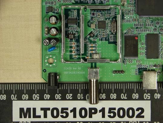
N7ZEC420
Oct 23, 2005CABLE MODEM
Equipment Class
JBP - Part 15 Class B Computing Device Peripheral
N7ZRT-710S
Jan 01, 2002Broadband Sharing Router
Equipment Class
JBP - Part 15 Class B Computing Device Peripheral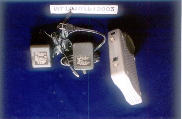
N7ZEC280
Nov 29, 2001DOCSIS Cable Modem
Equipment Class
JBP - Part 15 Class B Computing Device Peripheral